Thermo Scientific Smart-Vue Installation Manual
C02/temperature module
Hide thumbs
Also See for Smart-Vue:
- Administrator's manual (154 pages) ,
- Installation manual (35 pages) ,
- Installation manual (25 pages)
Table of Contents
Advertisement
Quick Links
Advertisement
Table of Contents

Related Manuals for Thermo Scientific Smart-Vue


Summary of Contents for Thermo Scientific Smart-Vue
- Page 1 Thermo Scientific Smart-Vue Installation 316266H0 January 2011...
- Page 2 Thermo Scientific products do not contain any internal components that require user intervention or repair. If the product or device shows signs of improper operation, disconnect it immediately from its power source and contact Thermo Scientific technical services so that the device can be examined under proper conditions.
-
Page 3: Table Of Contents
RoHS compliance ..............3 Introduction ................4 Package contents..............4 Product overview..............4 Main features ................5 What is a Smart-Vue wireless end-point module? .....6 Typical installation ..............7 Requirements and recommendations ........8 Where to find more information ..........9 Installation procedure ...............9 Placing your Smart-Vue module for best performance..... 9 Recommended order for installing end-point modules....10... -
Page 4: Notices
Scientific products are responsible for making sure that the product is fit for the intended usage. Do not open the product casing and do not disassemble or modify internal components in any manner. Thermo Scientific products do not contain any internal components that require user intervention or repair. -
Page 5: Electrical Warning
Do not cause a short-circuit with the electrical plug. Do not force either the AC or DC plug. Before removing the connector from the Smart-Vue™ end-point module or unplugging power cables, first unplug the cable from the power outlet. Do not subject adapter to physical shock, which could cause serious malfunction or damage. -
Page 6: Weee Compliance
Directive 2002/95/EC (RoHS Directive). Do not dispose of this product with household trash. Thermo Fisher Scientific recycles this product under certain conditions. Please contact us for more information. Thermo Fisher Scientific Smart-Vue CO and Temperature Module Installation Guide... -
Page 7: Introduction
Thermo Scientific CO detector/temperature monitoring end-point module. This guide describes how to get your new Smart-Vue end-point module up and running quickly. Detailed configuration instructions and software settings are provided in the complete Thermo Scientific Smart-Vue Software User Manual provided with your product. -
Page 8: Main Features
Smart-Vue Server/Smart-Vue Client system management software. This software enables you to completely configure your Smart-Vue end-point modules as well as handle alarms, alerts, and data storage quickly and reliably. Do not place the Smart-Vue wireless end-point module inside the incubator. -
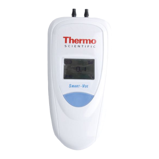
Page 9: What Is A Smart-Vue Wireless End-Point Module
Push-button Plug for DC adapter Cable to connect to CO2/temperature module’s ribbon cable Figure 2. Smart-Vue wireless end-point module with cable for CO end-point module CO2 Sensor Sensor intake intake Cable to connect to Smart-Vue module Cable to connect... -
Page 10: Typical Installation
PC on a TCP/IP receiver installed directly on an Ethernet network. Repeaters may be used when the wireless range between the receiver and the Smart-Vue end-point module is too great to achieve a strong signal. Figure 4below shows these basic configurations: Figure 4. -
Page 11: Requirements And Recommendations
24/7 monitoring. End-point modules with internal probes should not be placed in cold-rooms. Please see the relevant product manuals for details on installing Smart-Vue receivers and Smart-Vue Server/Smart-Vue Client software. Smart-Vue CO and Temperature Module Installation Guide... -
Page 12: Where To Find More Information
Where to find more This guide leads you through basic installation steps to get you started with your product. For more details, please see the Thermo Scientific Smart-Vue information Software User Manual. You may click on Help ==> User manual( ) to open it directly from within the Smart-Vue Client software. -
Page 13: Recommended Order For Installing End-Point Modules
Installation procedure Recommended order for In addition to placing your Smart-Vue end-point module as described above for best individual wireless performance, you may also optimize overall installing end-point network performance by proceeding as follows when installing multiple modules end-point modules: 1. -
Page 14: Preparing Mounting Kit With A Magnet (Optional)
Installation procedure Preparing mounting kit Your Smart-Vue end-point module includes a plastic holder so you can mount the device easily on various surfaces. In addition to the provided with a magnet (optional) screws, you will also find a magnetic pad with adhesive backing that you can use to adhere the holder to most metal surfaces easily. -
Page 15: Placing The Smart-Vue Module
Figure 6. Ribbon cable lies flat beneath door joint 4. Mount the Smart-Vue end-point module on the exterior of the chamber being monitored or on a suitable nearby surface (e.g. the wall) using the provided plastic holder, which you may mount using ®... - Page 16 7. Use the provided plastic cable holders to attach or coil the excess cable neatly. Note: When routing the cable for the Smart-Vue probe, avoid direct contact with or close proximity placement of the sensor cabling with any high voltage wiring. Cabling should be placed with no less than a minimum of 5 cm (2 inches) distance from high voltage components.
-
Page 17: Activating The End-Point Module (Automatic Wireless Setup)
(the AC adapter plugged into this end-point module is only used to wireless setup) power the sensor unit). To activate your Smart-Vue end-point module and add it automatically to your wireless monitoring network, do the following: 1. Insert the provided battery, if not already installed, making sure to respect the polarity (see image printed inside battery slot). -
Page 18: Refreshing The Module Display With A Short Press
Figure 10, we recommend that you avoid performing a long-press again, which consumes battery life for no reason. Refreshing the end-point You may refresh the Smart-Vue display with the latest sensor readings by performing a short press on the end-point module’s push-button. module display with a short press 1. -
Page 19: Software Configuration
Smart-Vue configuration Server/Smart-Vue Client configuration. Testing the connection You may use Smart-Vue Client to test the wireless signal strength as Checking wireless signal described here, entering your login name and password when prompted by strength the software. -
Page 20: Basic End-Point Module Configuration
The new end-point module into a group Smart-Vue should be listed as shown here, where “local” refers to the receiver and “SDP-local” refers to a generic group for new un-configured end-point modules connected to that receiver. - Page 21 6. Click on Close ==> Yes ==> OK to update the end-point module, save this change, and return to the tree structure, as shown here: Figure 14. CO /temperature sensors in “Group 1” group Smart-Vue CO and Temperature Module Installation Guide Thermo Fisher Scientific...
-
Page 22: Testing The End-Point Module By Running An On-Demand Read Or Status Update
Enter your login name and password when prompted. You may download sensor correction parameters directly over the Internet. Please see the Thermo Scientific Smart-Vue Software User Manual for more details. Thermo Fisher Scientific Smart-Vue CO... -
Page 23: Setting Basic Sensor Parameters
Software configuration Setting basic sensor 1. Access end-point module settings by pressing F11 or selecting parameters Settings ==> Sensor settings ( ) on the Smart-Vue Client main screen. Click on dials (dots) or double-click Hours/Minutes to set Figure 16. Main sensor settings screen applies to both sensors 2. -
Page 24: Setting High And Low Alarm Levels
Figure 18. F11 ==> Alarm settings tab for temperature sensor 3. Click on Close ==> Yes ==> OK to save your settings. Please see the Thermo Scientific Smart-Vue Software User Manual for more details on these and other important features. Click on Help ==> User Manual ( ) to open the PDF file directly. -
Page 25: Appendix
Also check to make sure the receiver is working properly. Is it OK to have a signal strength of 25% for my Smart-Vue end-point module? No. The signal for each device must show a value higher than 30% when you click on the Power button in Smart-Vue Client. - Page 26 Appendix Smart-Vue end-point • ISM (Industrial Scientific Medical) band with four frequencies: US/CAN 915 MHz; Europe 868 MHz; APAC 434 MHz; India and module specifications other countries 867 MHz • Channel width: 50 kHz • Frequency deflection: 16 KHz •...
-
Page 27: Specifications
Calibration points: calibration in comparison at +37°C / 80% RH and 5% CO . Other points upon request. • IP44 protection, plastic casing (ABS, Polycarbonate) with PTFE filter, 0 to 90% RH non condensing for indoor use Smart-Vue CO and Temperature Module Installation Guide Thermo Fisher Scientific... -
Page 28: Contact Information
Appendix Contact information By e-mail If you need help with your Thermo Scientific product, please send a detailed e-mail to us at the following address: E-mail: service.led@thermofisher.com Be sure to include as many details as possible, including specific product references, software versions and screen shots from your computer.
Need help?
Do you have a question about the Smart-Vue and is the answer not in the manual?
Questions and answers