Table of Contents
Advertisement
Quick Links
Advertisement
Table of Contents

Related Manuals for Thermo Scientific NICOLET FT-IR


Summary of Contents for Thermo Scientific NICOLET FT-IR
- Page 2 The information in this publication is provided for reference only. All information contained in this publication is believed to be correct and complete. Thermo Fisher Scientific shall not be liable for errors contained herein nor for incidental or consequential damages in connection with the furnishing, performance or use of this material.
-
Page 3: Table Of Contents
Contents Introduction..................1 Questions and concerns ............... 2 Conventions used in this manual ..........2 Safety precautions................ 3 TGA-IR Module components ............4 The front panel............... 5 The rear panel ................ 7 Using the TGA-IR Module ..............9 Principles of operation ..............9 Setting up the module .............. -
Page 5: Introduction
OMNIC Series Help. Before operating the TGA-IR Module, you should have a working ™ knowledge of Thermo Scientific OMNIC Series software. You will also need to know the fundamentals of thermogravimetric analysis and the operating characteristics of your thermogravimetric analyzer. -
Page 6: Questions And Concerns
Questions In case of emergency, follow the procedures established by your facility. If you have questions or concerns about safety or need and concerns assistance with operation, repairs or replacement parts, you can contact our sales or service representative in your area or use the information at the beginning of this document to contact us. -
Page 7: Safety Precautions
Safety precautions Before you use the TGA-IR Module, make sure you read the following safety precautions and both the Spectrometer Safety Guide and the Accessory Safety Guide that came with your system. To help prevent personal injury or equipment damage, follow all safety precautions whenever you use the TGA-IR Module. -
Page 8: Tga-Ir Module Components
TGA-IR The TGA-IR Module and its internal components are shown in the following illustrations. Module components Electronics box Gas cell Detector Mirror Mirror Exhaust gas line Transfer line Mirror Thermo Fisher Scientific... -
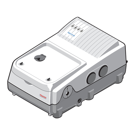
Page 9: The Front Panel
The front panel The four indicator lights on the front panel of the TGA-IR Module show the current status of the system. TGA-IR Module User’s Guide... - Page 10 The table below describes the function of each indicator light on the front panel: Indicator Function Power This indicator is lit whenever the module power is on. The power switch is on the rear panel. (See the illustration in the next section.) Transfer Line This indicator is lit when the transfer line is being heated.
-
Page 11: The Rear Panel
The rear panel The following table and illustrations describe the components on the rear panel of the TGA-IR Module. Accessory Start Purge in AC power Power Fuses connector switch This component… Does this… Purge In Connects the purge gas supply. Start Connects a remote start cable from the TGA. - Page 12 Warning The Module is preset at the factory to connect to a particular AC line voltage range. As shown below, the “Factory Set” label on the rear panel indicates the factory setting. To avoid shock and fire hazard, do not attempt to change the setting. Contact Technical Support if your system does not meet your local power standards.
-
Page 13: Using The Tga-Ir Module
Using the TGA-IR Module This chapter provides information about: • Principles of operation for the TGA-IR Module. • Setting up the module. • Cooling the detector. • Checking the performance of the TGA-IR Module. • Tips for operating the TGA-IR Module. Note Maintenance and service information for the gas cell is provided in the TGA-IR Module Gas Cell Service Guide that came with your... -
Page 14: Setting Up The Module
A carrier gas continuously sweeps evolved gases from the furnace tube chamber. The carrier gas may be inert, such as nitrogen, or oxidative, such as air. As the compounds in the sample vaporize, the carrier gas carries them through a heated transfer line and flow cell. Here the gases are scanned by the infrared beam and the spectral data is recorded. - Page 15 Note You should leave the purge on at all times. This keeps the module free of undesirable gases, protects the optics and improves the system’s thermal stability. Important Do not purge with argon. Purging with argon will cause the laser to fail.
-
Page 16: Connecting The Transfer And Exhaust Gas Lines
Connecting In a TGA-IR experiment, the sample gases from the TGA furnace are conducted into the gas cell through the transfer line. The exhaust the transfer and gases produced during this process can be hazardous and should be exhaust gas lines vented through the exhaust gas line. - Page 17 3. Connect the transfer line to the gas cell transfer line connector. ® Gently push the Swagelok fitting on the transfer line into the gas cell transfer line connector. Turn the Swagelok fitting until tight to secure the connection. Transfer line from TGA furnace Gas cell transfer line connector...
- Page 18 4. Connect the exhaust gas line to the gas cell exhaust gas connector. ® Gently push the Swagelok fitting on the exhaust gas line into the gas cell exhaust gas connector. Turn the Swagelok fitting until tight to secure the connection. Exhaust gas line to venting system Gas cell exhaust...
-
Page 19: Verifying The Installation
6. Adjust the transfer line flow rate. The TGA-IR Module is intended for use at ambient pressure, with low pressure (5 psi or less) carrier gases flowing at a rate of 150 ml/minute or less. For information about adjusting the transfer line flow rates, refer to the manufacturer’s documentation that came with your furnace. -
Page 20: Setting The Temperature
Setting the temperature To set the temperature of the TGA-IR Module, use the OMNIC Series software. For more information, please refer to the on-line OMNIC Series Help available through the Series menu in OMNIC. Find “heaters” in the index and go to the “Heaters parameters” topic. Note The cell and transfer line are heated to help prevent the condensation of materials in the gas stream from the TGA furnace, but you should... -
Page 21: Cooling The Detector
2. Attach the “ground” and “start collection” wires to the remote start connector supplied by the manufacturer of your TGA furnace. For more information about the remote start connector for your TGA furnace, contact the manufacturer or see the manufacturer’s documentation. - Page 22 1. Open the dewar cover and remove the plastic stopper from the dewar. Plastic stopper Dewar cover Warning Make sure you pour the liquid nitrogen slowly when you fill the vacuum bottle or the detector dewar. Pouring too quickly can cause liquid nitrogen to spray out.
-
Page 23: Operating Tips
Note A small amount of liquid nitrogen typically spills out of the funnel when you are filling the dewar. This will not harm your TGA-IR Module. 4. Pour the liquid nitrogen slowly into the funnel. Fill the funnel and then let it drain completely two or three times. Wait until the vapor plume disappears and then repeat until the dewar is filled. - Page 24 • A weight loss of about 10 mg usually gives an adequate signal. For example, if a sample loses 50% of its weight during the run, a 20 mg sample size will probably be adequate. Do not use excessively large sample sizes. Large weight losses (in terms of mass) can be accompanied by using aerosols that cause IR baseline shifts.
-
Page 25: Maintenance
Maintenance This chapter provides information about: • Checking and replacing fuses. • Troubleshooting. • Electrical specifications of the TGA-IR Module. Note Maintenance and service information for the gas cell is provided in the TGA-IR Module Gas Cell Service Guide that came with your TGA-IR Module. -
Page 26: Checking And Replacing Fuses
Checking and If the indicator lights on the front panel fail to light, the fuses in the TGA-IR Module may need to be replaced. This procedure should replacing fuses take 10 minutes or less, and you will need 1/8 inch flat-blade screwdriver. - Page 27 The following table shows the specifications for replacement fuses: For 220-240 VAC Systems For 100-120 VAC Systems 3 ampere 6 ampere 250 volt 250 volt 5 x 20 mm 0.25 x 1.25 in Series 3AG Series 3AG F-type (also known as F-type (also known as quick-acting or fast-blo) quick-acting or fast-blo)
- Page 28 3. Remove the fuse holder from the fuse compartment. Use a 1/8 inch flat-blade screwdriver to pry the fuse cover open, and then pry the fuse holder out of the fuse compartment. Fuse cover Fuse holder Thermo Fisher Scientific...
- Page 29 4. If a fuse needs to be replaced, remove it from the fuse holder and replace it with a new fuse of the correct type and amperage rating. See the table at the beginning of this section for fuse replacement specifications.
-
Page 30: Troubleshooting
Troubleshooting Low infrared throughput is a problem you may encounter with your TGA-IR Module. To help recognize when this is happening, you should keep a record of peak-to-peak interferogram voltages, single- beam spectra, performance test results (see “Checking performance” in the “Using the TGA-IR Module” of this manual), and 100% lines. You should also record the cell temperature, the number of scans and the resolution. -
Page 31: Specifications
Specifications The electrical specifications of the TGA-IR Module are shown in the table below: Maximum power consumption 408 W AC voltage 100 to 120 VAC 220 to 240 VAC Current at AC voltage* 2.7 A at 100 VAC 3.2 A at 120 VAC 1.5 A at 220 VAC 1.7 A at 240 VAC * The module is preset at the factory to connect to a particular AC line voltage...
Need help?
Do you have a question about the NICOLET FT-IR and is the answer not in the manual?
Questions and answers