Table of Contents
Advertisement
Quick Links
Advertisement
Table of Contents
Troubleshooting

Related Manuals for Viavi SmartOTDR Mainframe


Summary of Contents for Viavi SmartOTDR Mainframe
- Page 1 SmartOTDR Mainframe Handheld Fiber Tester User Manual...
- Page 3 SmartOTDR Mainframe Handheld Fiber Tester User Manual VIAVI Solutions 1-844-GO-VIAVI www.viavisolutions.com...
- Page 5 Copyright © Copyright 2023 VIAVI Solutions Inc. All rights reserved. No part of this guide may be reproduced or transmitted, electronically or otherwise, without written permission of the publisher. VIAVI Solutions and the VIAVI logo are trademarks of VIAVI Solutions Inc.
- Page 6 Instructions for returning waste equipment and batteries to VIAVI can be found in the WEEE section of VIAVI's Standards and Policies web page. If you have questions concerning disposal of your equipment or batteries, contact the VIAVI WEEE Program Management team at WEEE.EMEA@VIAVISolutions.com.
-
Page 7: Table Of Contents
Table of Contents About This Guide xiii Purpose and scope......... xiv Assumptions . - Page 8 Table of Contents First use of the battery......... 14 Charging the Li-Po battery .
- Page 9 Pre-requisite for using the Smart Access Anywhere Application ..61 Downloading the VIAVI application on PC ......61 Downloading the VIAVI application on Tablet/Smartphone .
- Page 10 Table of Contents Connecting the SmartOTDR to Stratasync ......81 Chapter 8 File management File Explorer Overview ........84 Directories and Files selections .
- Page 11 Table of Contents Environment ..........98 Temperature.
- Page 12 Install options from VIAVI Server ........
-
Page 13: About This Guide
About This Guide VIAVI SmartOTDR is an handheld OTDR designed for the construction, turn-up and maintenance of fiber networks. The topics discussed in this chapter are as follows: • “Purpose and scope” on page xiv • “Assumptions” on page xiv •... -
Page 14: Purpose And Scope
SmartOTDR effectively and efficiently. We are assuming that you have basic computer and mouse/track ball experience and are familiar with basic telecommunica- tion concepts and terminology. Technical assistance If you require technical assistance, call 1-844-GO-VIAVI. For the latest TAC information, go to http://www.viavisolutions.com/en/services-and-support/support/technical-assis- tance. - Page 15 About This Guide Conventions Table 1 Typographical conventions Description Example Code and output messages appear in All results okay this typeface. Text you must type exactly as shown Type: in the dialog box a:\set.exe appears in this typeface. Variables appear in this typeface. Type the new hostname Book references appear in this typeface.
- Page 16 About This Guide Conventions NOTE This symbol represents a Note indicating related information or tip. This symbol, located on the equipment or its packaging indicates that the equipment must not be disposed of in a land-fill site or as municipal waste, and should be disposed of according to your national regula- tions.
-
Page 17: Chapter 1 Safety Information
Safety information Chapter 1 This chapter gives the main information on the safety conditions when using the Smar- tOTDR: • “Battery and AC/DC safety information” on page 2 • “Optical Connectors Handling Precaution” on page 3 • “Laser Safety instructions” on page 3 User Manual 7SMART102 Rev006... -
Page 18: Battery And Ac/Dc Safety Information
• Do not use any mains adaptor or battery other than those supplied with the unit, or supplied by VIAVI as an option for this unit. If another adapter or battery is used, it may damage the SmartOTDR itself. Using the SmartOTDR with a battery other than the one supplied by the manufac- turer of the SmartOTDR may entail risks of fire or explosion. -
Page 19: Optical Connectors Handling Precaution
Chapter 1 Safety information Optical Connectors Handling Precaution • Do not attempt to service this product yourself, as opening or removing covers may expose you to dangerous, high voltage points and other hazards. Contact qualified service personnel for all service. Optical Connectors Handling Precaution •... -
Page 20: Warning Labels For The Laser Classes
Chapter 1 Safety information Laser Safety instructions Warning labels for the laser classes Due to the reduced dimensions of the optical modules, it is not possible to attach the required warning labels to them. In line with the provisions of Article 7.1 of the IEC 60825-1: 2014 standard, the laser class identification labels are shown below: Reference standard IEC 60825-1: 2014... -
Page 21: Introducing The Smartotdr
Introducing the SmartOTDR Chapter 2 This chapter provides a general description of the SmartOTDR. Topics discussed in this chapter include the following: • “Unpacking the SmartOTDR” on page 6 • “Hard keys and Indicators” on page 8 • “Power Supply” on page 9 User Manual 7SMART102 Rev006... -
Page 22: Unpacking The Smartotdr
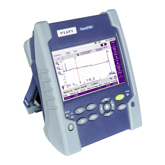
Check if all standard accessories are included in the box. Optional accessories might be delivered in a separate box. If any part is missing or damaged please contact your local VIAVI customer service. Each SmartOTDR comes with: Table 5... - Page 23 Chapter 2 Introducing the SmartOTDR Unpacking the SmartOTDR Figure 2 SmartOTDR: Front view 5’’ Color Capacitive Touchscreen Indicators Buzzer Hard keys Figure 3 SmartOTDR: Side and top views Mini USB AC/DC USB host Optical test port (OTDR, light port Input source and optional Power Meter) User Manual...
-
Page 24: Hard Keys And Indicators
Chapter 2 Introducing the SmartOTDR Hard keys and Indicators Hard keys and Indicators Front panel hard keys Figure 4 Hard keys and Indicators Table 6 Hard keys description Hard key Function Power (ON/OFF) button To access the File Explorer and manage test results. To access the Home page. -
Page 25: Front Panel Led Indicators
Chapter 2 Introducing the SmartOTDR Power Supply Front panel LED indicators The SmartOTDR is equipped with three LED indicators, lit into a different color according to the status of the unit. Table 7 Indicators Status On indicator Blinking The unit is off and connected to an external power source. green The unit is on, connected to an external power supply or Solid green... - Page 26 Chapter 2 Introducing the SmartOTDR Power Supply Figure 5 SmartOTDR power supply Power supply plug Interchangeable plugs EUROPE AUSTRALIA adaptable plug adaptable plug adaptable plug adaptable plug User Manual 7SMART102 Rev006...
-
Page 27: Starting Up
Starting up Chapter 3 This chapter describes the first steps to perform when using the SmartOTDR. The topics discussed in this chapter are as follows: • “Setting the adaptable plug to the mains adapter” on page 12 • “Charging the battery” on page 13 •... -
Page 28: Setting The Adaptable Plug To The Mains Adapter
Chapter 3 Starting up Setting the adaptable plug to the mains adapter Setting the adaptable plug to the mains adapter The SmartOTDR is supplied as standard with a mains adapter and 4 country adaptable plugs (Europe / UK / US / Australia). Setting the correct plug to the mains adapter Slide AC plug into adapter body as shown below. -
Page 29: Charging The Battery
Chapter 3 Starting up Charging the battery Figure 7 Removing the adaptable plug from the mains adapter Charging the battery CAUTION Upon reception of the product, the battery of the SmartOTDR needs to be fully recharged, no later than 6 months after the date of calibration. If the product is unused for a long period, the battery needs also to be periodically fully recharged, with a period not longer than 12 months Connecting the mains adapter... -
Page 30: First Use Of The Battery
Chapter 3 Starting up Charging the battery First use of the battery When the unit is being used for the very first time or when the battery has been replaced, the unit is not able to detect the charge level of the new battery. In that case, the icon is displayed on the upper banner of the screen. -
Page 31: Turning The Smartotdr On And Off
If the equipment is powered to mains, the battery will charge. The On indicator pass from blinking to solid green. The VIAVI logo appears on the screen while an auto test is carried out. The unit is ready to be used when the Home page or running test application is displayed. -
Page 32: Built-In Kickstand
Chapter 3 Starting up Built-in kickstand NOTE Unless specified otherwise in this documentation, the settings configured on the unit are kept in memory even when the unit is turned off. NOTE If the unit stops responding, you can force a hardware reset by pressing and holding down the ON/OFF button for about 4 seconds. -
Page 33: First Startup: Configuring The Regional Settings
Chapter 3 Starting up First startup: configuring the regional settings Figure 8 SmartOTDR «seated» and «standing» user positions Stand Pull to lift the stand First startup: configuring the regional settings The first time the SmartOTDR is turned on, the screen displayed allows to configure regional settings (language, date, time, date &... - Page 34 Chapter 3 Starting up First startup: configuring the regional settings Touch Language and select a language from he list. Touch Date and enter the current date, using the numeric keypad displayed using the menu key Edit Number. Touch Time and enter the current time, using the numeric keypad displayed using the menu key Edit Number.
- Page 35 Setting-up the SmartOTDR Chapter 4 This chapter describes the operations for configuring the instrument. The topics discussed in this chapter are as follows: • “Displaying the System Settings screen” on page 20 • “Configuring screen and display settings” on page 21 •...
-
Page 36: Chapter 4 Setting-Up The Smartotdr
Chapter 4 Setting-up the SmartOTDR Displaying the System Settings screen Displaying the System Settings screen To display the System Settings screen, you must: Press the H hard key to reach the Home page. Figure 10 Home page Activate the Settings icon to open the System Settings screen. -
Page 37: Configuring Screen And Display Settings
Chapter 4 Setting-up the SmartOTDR Configuring screen and display settings Configuring screen and display settings In the System Settings page, the following parameters can be defined: Backlight Touch Backlight Define the backlight level of the screen, using the left and right direction keys, or press Edit Number softkey and use the displayed keypad. -
Page 38: Defining The Automatic Shutdown And The Storage Limit
Chapter 4 Setting-up the SmartOTDR Defining the Automatic shutdown and the storage limit Defining the Automatic shutdown and the storage limit Automatic shutdown The automatic shutdown function turns off the SmartOTDR automatically when the unit has been inactive for a specified amount of time. Work in progress is automatically saved. -
Page 39: Chapter 5 Optical Options
Optical options Chapter 5 The unit can be equipped with an optional built-in Visual Fault Locator (VFL). The topics discussed in this chapter are as follows: • “Optical Power Meter and Light Source Functions” on page 24 • “Built-in Visual Fault Locator (VFL) Function” on page 24 User Manual 7SMART102 Rev006... -
Page 40: Optical Power Meter And Light Source Functions
Chapter 5 Optical options Optical Power Meter and Light Source Functions Optical Power Meter and Light Source Functions For power meter and light source functions, please refer to the OTDR User Manual. Figure 12 Optical connectors Light source and power meter via OTDR port (see OTDR User Manual) Built-in Visual Fault Locator (VFL) Function... - Page 41 Chapter 5 Optical options Built-in Visual Fault Locator (VFL) Function Connect the fiber to the VFL port located at the top of the unit. Press the H key and activate the VFL Select CW for Continuous Wave Mode or 1 Hz for Pulsed Mode. Figure 13 VFL activation When VFL is active, the icons...
- Page 42 Chapter 5 Optical options Built-in Visual Fault Locator (VFL) Function User Manual 7SMART102 Rev006...
-
Page 43: Microscope Application
Microscope application Chapter 6 The microscope application is a hot-plug feature enabled when connecting a VIAVI fiber inspection microscope to a VIAVI instrument that supports optical fiber testing. The topics discussed in this chapter are as follows: • “Microscope Overview” on page 28 •... -
Page 44: Microscope Overview
Chapter 6 Microscope application Microscope Overview Microscope Overview A probe microscope enables verification that optical fiber connectors are sufficiently defect-free and suitable for service. The P5000i Digital Probe Microscope and the FiberChek Probe Microscope are portable handheld microscopes used to view and inspect both the bulkhead (female) and patch cord (male) sides of fiber optic connectors as well as other optical devices like trans- ceivers. -
Page 45: Connecting The Microscope
Chapter 6 Microscope application Connecting the microscope Fig. 15 FiberChek Probe Overview Power Button (side) Touchscreen Display Inspection Tip Magnification / Return Button Autofocus Trigger Manual Focus / Navigation Control Action Button Micro-USB Interface (bottom) Connecting the microscope P5000i probe USB connection Plug the P5000i probe into a USB port from the SmartOTDR. -
Page 46: Fiberchek Probe Usb Connection
Chapter 6 Microscope application Connecting the microscope Verify that WLAN Mode = Wireless Client Touch S SSID to locate the microscope. Fig. 16 Microscope FiberChek detected via WIFI Touch the FiberChek SSID. Touch Select. The FiberChek SSID will appear under Configuration. Touch Connect SSID. -
Page 47: Configuring The Microscope
Chapter 6 Microscope application Configuring the microscope Figure 17 USB connection of the FiberChek probe Touch the Home button. Launch the Microscope application More than one application may be active on the instrument (e.g., both inspection and OTDR). Connect the probe to the fiber being inspected using the appropriate tip. Configuring the microscope Test Setup Launch the microscope application and connect a fiber to the probe inspection... - Page 48 Chapter 6 Microscope application Configuring the microscope Figure 18 Scope Live view Touch the Setup softkey Touch the Test Setup link Figure 19 P5000i Scope Setup Touch the Profile dropdown box and select the Profile to be used for automated end face image analysis.
- Page 49 Chapter 6 Microscope application Configuring the microscope Figure 20 Profiles’ List The profile contains the failure criteria used during automated assessment of the end face image. Touch the Tip Setting dropdown box and select the Tip Setting to be used to illuminate the fiber end face.
-
Page 50: Link Description
Chapter 6 Microscope application Configuring the microscope Yes: meter is Green when the image is sufficiently in focus for automated analysis. Red when the image focus is too low. No: indication of focus level via colors is disabled Link Description Launch the microscope application and connect a fiber to the probe inspection tip. - Page 51 Chapter 6 Microscope application Configuring the microscope Touch the Fiber Id setup icon to change the name used to identify the fiber under test. An alphanumeric keypad is displayed to facilitate creation of a new name Touch the Fiber Number setup icon to change the number used to identify the fiber under test.
-
Page 52: File Configuration
Chapter 6 Microscope application Configuring the microscope Figure 22 Header of the PDF report File configuration Launch the microscope application and connect a fiber to the probe inspection tip. Touch the Setup softkey Touch the File Configuration link Figure 23 File configuration Touch the Dir. - Page 53 Chapter 6 Microscope application Configuring the microscope Touch the "[auto]" key to expose a list of useful recommendations like Function / Job_Id or Current_Dir. The directory name after making changes is indicated in the gray box immedi- ately below Dir. Naming. Fig.
-
Page 54: Tip And Profile Management
Chapter 6 Microscope application Configuring the microscope Touch the Logo setup icon to add a custom logo to test reports Copy a logo file in JPG format to a USB flash drive. Plug the USB drive into the instrument. Navigate to the USB drive. Select the logo file. - Page 55 Chapter 6 Microscope application Configuring the microscope Touch the Add softkey to add a new tip setting: Copy the new tip setting onto a USB flash drive. Plug the USB drive into the instrument. Navigate to the USB drive. Select the tip setting file. Touch Load.
-
Page 56: Using The Microscope
Chapter 6 Microscope application Using the microscope Using the microscope Running an automated test Launch the microscope application. Connect a fiber to the probe inspection tip. Focus the end face image: Use the focus control wheel if a P5000i microscope or the autofocus trigger if a FiberChek microscope. - Page 57 Chapter 6 Microscope application Using the microscope Figure 29 Scope Test results Touch the zone information box to hide the box and the overlays. Touch the overlays icon to unhide the zone information box and the over- lays. Touch the information icon to view additional test result details.
-
Page 58: Viewing Prior Images (Mosaic Mode)
Chapter 6 Microscope application Using the microscope Figure 31 Magnified images Touch the Comment softkey to add a note to a saved test result: – An alphanumeric keypad is displayed to facilitate adding a comment. – The comment will appear on the bottom left corner of the image and on reports. Touch the Live softkey to exit the tested or captured image view. -
Page 59: Accessing Online Help
Chapter 6 Microscope application Using the microscope Figure 32 Mosaic mode Touch the Magnify softkey to toggle between low and high magnification image views. Touch an image to select it. A yellow outline will appear around the selected image. Touch the Full softkey to return to a single-image, full screen view. - Page 60 Chapter 6 Microscope application Using the microscope User Manual 7SMART102 Rev006...
-
Page 61: Connectivity
Connectivity Chapter 7 This chapter describes the different ways to access to the SmartOTDR interface or content using different connection modes. Topics described in this chapter are as follows: • “Establishing connection” on page 46 • “Remote Control” on page 59 •... -
Page 62: Establishing Connection
Chapter 7 Connectivity Establishing connection Establishing connection Checking Bluetooth/WIFI option is installed Once the WIFI/Bluetooth option is installed (see “Installing the Bluetooth/WIFI option” on page 131): Turn on the SmartOTDR, pressing O button. On the Home page, press Connectivity icon Check the following icons are displayed according to the option(s) installed: You can also go in Settings >... - Page 63 Chapter 7 Connectivity Establishing connection Figure 33 Bluetooth disabled Press the menu key Bluetooth to enable the Bluetooth interface. The icon is displayed on the upper banner of the screen The Paired Bluetooth Devices screen appears Press the Become Pairable soft key to wait for another device to initiate the connection to the SmartOTDR.
-
Page 64: Searching New Devices To Be Paired With The Platform
Chapter 7 Connectivity Establishing connection Both equipment are now paired: Figure 35 Platform paired with one equipment The icon has a blue background when paired with a device , versus no back- ground when not paired Searching new devices to be paired with the Platform If the desired device is not displayed on the screen, or if no devices are detected, press the Search Devices soft key. -
Page 65: Removing The Pairing
Chapter 7 Connectivity Establishing connection Figure 36 List of devices found Select the device to be paired with the Platform It will be underlined in blue. Push the Pair key to connect the device to the Platform If prompted, enter a pairing code. The code must be identical on the SmartOTDR and the device. -
Page 66: Via Wifi
Chapter 7 Connectivity Establishing connection Via Wifi Configuring the WiFi access Restart the SmartOTDR, pressing O button. On the Home page, press Connectivity The Connectivity page opens. In the new page, select the WIFI icon The WiFi Setup screen displays. Press Wireless menu key to enable the Wifi interface. -
Page 67: Connection To Ssid
Chapter 7 Connectivity Establishing connection Figure 38 List of SSIDs found Select the desired network to connect to. Press Select menu key to validated the connection. The display goes back to Setup screen. The SSID parameter is automatically configured with the one selected. In Encryption parameter, select the type of encryption wished: None, WEP Static, WPA Personal, WPA Enterprise. -
Page 68: Configuring The Wifi Mode To Which The Platform Is Connected
Chapter 7 Connectivity Establishing connection Configuring the WiFi mode to which the Platform is connected To work on WIFI with the Platform, configure the 802.11 parameter on the WIFI Setup screen. Select the mode of connection: • Config 1 to 4 static mode enabling input of the configuration of 4 sites. -
Page 69: Creating A Network From The Smartotdr
Chapter 7 Connectivity Establishing connection – Select Manual to enter manually the Proxy address – Select Auto and enter the Pac address. Creating a network from the SmartOTDR A WIFI network can be created from the SmartOTDR, in order to associate it to a Smart- phone or Tablet. -
Page 70: Configuring The Smartotdr Via Ethernet
Chapter 7 Connectivity Establishing connection Make sure the network configuration onto the PC is set to the Dynamic mode: Click on Start > Control Panel. Double click on Network Connection. Double click on Local Area Connection. In the dialog box, click on Properties. Check the parameter Internet Protocol (TCP/IP) is selected ( ) and click once on it (underlined in blue) - Page 71 Chapter 7 Connectivity Establishing connection • the screen cannot be remote on to a PC or on to another SmartOTDR. • Session Mode the Remote screen function is inactive once the SmartOTDR is switched off. • Permanent Mode the Remote screen function is still active when the SmartOTDR is switched off and restarted.
-
Page 72: Via Cloud Storage
Chapter 7 Connectivity Establishing connection SmartOTDR reverses to static IP address mode with User1 IP address. NOTE Once the SmartOTDR is connected to the network, the icon indicates the connection is working. Proxy > Use proxy Select No if no proxy is used. If Manual has been selected, enter the Proxy Address. -
Page 73: Configuring And Connecting To Cloud Storage On The Smartotdr
Chapter 7 Connectivity Establishing connection Before configuring the Cloud Storage on Platform, you must first create an account on a Cloud Platform on internet. The Cloud storage function onto the SmartOTDR works exclusively with sites using the WebDav technology such as CloudSafe (https://secure.cloudsafe.com/ pages/index.html) or Box (https://www.box.com/pricing/). - Page 74 Chapter 7 Connectivity Establishing connection Figure 43 Example of configuration Configuration on SmartOTDR Configuration on Cloud server (example with CloudSafe) Connecting Cloud Storage Once configuration has been established on the SmartOTDR, it is ready to be connected with Cloud server: Select one parameter of the Cloud Storage window on SmartOTDR Press Connect Cloud Storage menu key The connection launches.
-
Page 75: Remote Control
SmartOTDR or to access the internal memory / USB memory stick contents on the PC and perform files transfer from SmartOTDR to PC and vice-versa. This feature does not need any license code if the user wants assistance from a VIAVI person located within the VIAVI network. - Page 76 WIFI connection USB/WIFI connection via Smartphone (Tethering) To access to a SmartOTDR remotely, the connection between the unit and the VIAVI application can be established via a USB cable or WIFI, and through a Smartphone, having Internet Sharing capability via USB or WIFI.
-
Page 77: Pre-Requisite For Using The Smart Access Anywhere Application
Smartphone from given list and having appropriate basic subscription for internet connection sharing. Downloading the VIAVI application on PC The VIAVI application Smart Access Anywhere must be downloaded on the PC which will be connected to the SmartOTDR remotely. NOTE It is not necessary to have administrator privileges to install the VIAVI appli- cation on PC. - Page 78 Chapter 7 Connectivity Remote Control On PC, open an internet browser page and type the following address: http:// smartaccess.updatemyunit.net Click on the link SmartAccessAnywhere_Vxx.xx.xx.zip Select Save in the dialog box. Open the directory into which has been save the zip file and unzip files into a directory Open the directory and double click on SmartAccessAnywhere.exe The Smart Access Anywhere application opens:...
-
Page 79: Downloading The Viavi Application On Tablet/Smartphone
SmartOTDR remotely. NOTE It is not necessary to have administrator privileges to install the VIAVI appli- cation. This application is just saved on the smartphone or tablet. On Smart device, open an internet browser page and type the following address: http://smartaccess.updatemyunit.net... - Page 80 Chapter 7 Connectivity Remote Control Figure 49 Access code displayed Note this access code and transfer it to the distant user, who will access the unit remotely. Press OK to hide the message. On the distant PC On the PC of the distant user, once the application is launched, enter the Access Number on the upper part of the screen.
-
Page 81: Using Remote Screen And File Transfer Applications
Chapter 7 Connectivity Remote Control Figure 50 Smart Access Anywhere: Home page Information on connection After remote upgrade or reboot, please wait for more than 2 minutes before re-starting the link between the PC and the unit with SmartAcc- essAnywhere. Using Remote screen and File Transfer applications Once the Introduction page is displayed, the user can work on distant SmartOTDR: •... - Page 82 Chapter 7 Connectivity Remote Control Figure 51 Smart Access Anywhere: Remote screen Virtual control buttons bar The VNC icon on the upper banner of the unit indicates the remote screen is active. On the upper part of the screen, the virtual control buttons bar is permanently displayed and allows to emulate hard keys.
- Page 83 Chapter 7 Connectivity Remote Control Figure 52 File Transfer page SmartOTDR Directories and files Storage media available Double-click on one directory/storage media to display the contents (directories / sub-directories / files) Navigation buttons Return to the Home directory click Select the PC drive in the list Access to parent directory Transferring files from PC to SmartOTDR On the SmartOTDR explorer, select the storage media, and if wished the (sub-...
- Page 84 Chapter 7 Connectivity Remote Control At the bottom of the screen, a new banner displays with information on file transfer: Information on file transfer Figure 53 1: location of the uploaded file on PC 3: level of transferred data 2: location of the file on SmartOTDR 4: bar graph of the transfer once transfer is completed in progress...
-
Page 85: Working With Files And Directories On Smartotdr
Chapter 7 Connectivity Remote Control Working with files and directories on SmartOTDR Renaming file or directory Select a file/directory stored on the SmartOTDR hard disk or USB key. Click on In the new dialog box opened, enter a new name for the file/ directory, keeping the file extension. - Page 86 Chapter 7 Connectivity Remote Control Figure 54 Session page This page gives information on connection «in real time». Modifying connection settings To modify the settings for connection to internet: Press Session menu key on left of the screen Disconnect from application pressing On the session screen (see Figure 54 on page 70), press button...
- Page 87 Chapter 7 Connectivity Remote Control Figure 55 Connection settings By default, the connection is defined to Smart-guess (default). To modify the current parameters, select Forced settings. The parameters for Port configurations turn automatically active. Modify, if necessary, the port used: Default port (22) is selected by default Select Alternative port (443) if necessary If the parameter Alternative port (443) is selected, you can defined if the proxy is used or not in the following parameter.
- Page 88 Chapter 7 Connectivity Remote Control Testing connection Before entering the Access code to activate the application, the connection to internet can be tested from displayed screen. Open the Smart Access Anywhere application on PC Press button The test is automatically launched Press to display logs in real time Once completed, the results for connection display:...
-
Page 89: Data Transfer
Chapter 7 Connectivity Remote Control Data Transfer The SmartOTDR enables to transfer files, from or toward the product using Wifi, Blue- tooth or Ethernet connection. Transferring files via Bluetooth Once the connection has been established with a bluetooth device: On the Home page, press File Explorer key to go in the File Explorer. Select the file(s) to be transferred from the Platform toward the PC. -
Page 90: Transferring Files To/From A Pc Via Wifi Or Ethernet
Chapter 7 Connectivity Remote Control Figure 58 Confirmation of file receiving WARNING The files stored in bluetooth-inbox will be lost once the SmartOTDR is switched off. Copy/Paste the files to keep toward another storage media (disk, usb key...). Transferring files to/from a PC via WIFI or Ethernet Once connection is established between the Platform and the PC: On the PC, use an FTP client, and access to internal memory via an internet browser page (I.E, Mozilla Firefox...). -
Page 91: Transferring Files Using Cloud Storage
Chapter 7 Connectivity Remote Control Figure 59 Internal memory of the SmartOTDR Internal memory open via Internet Explorer Internal memory open via Windows Explorer If internal memory of the Platform is accessible via Internet Explorer (or any other explorer), right click on one file and click on Save target as... to transfer file onto the PC. -
Page 92: Vnc
Chapter 7 Connectivity Remote Control Figure 60 File Explorer with cloud storage Edition menu The cloud storage is automatically disconnected once the SmartOTDR is switched off. Reconnect from the System Settings page of the Smar- tOTDR after the Platform restart. The SmartOTDR can be used in combination with a PC in order to transfer the Interface onto a PC. -
Page 93: Virtual Control Buttons Bar
Chapter 7 Connectivity Remote Control Install a VNC viewer on your PC and open a VNC window. Considering 10.33.22.49 is the IP Address of the SmartOTDR (as shown Figure 39 on page 52), enter this IP address in the VNC window Press Enter to validate. -
Page 94: Equivalence Between The Keyboard And Smartotdr
Chapter 7 Connectivity Remote Control The virtual control buttons bar is displayed during a few seconds. You may click on any of these buttons to obtain exactly the same results than using the hard keys on the front panel of the SmartOTDR. Equivalence between the keyboard and SmartOTDR The PC keyboard can replaced all the buttons and keys of the SmartOTDR except the button... -
Page 95: Stratasync
Principle and prerequisites of the Stratasync Stratasync is a new solution that provides network operators with an agile and central- ized way to manage and analyze data from thousands of deployed VIAVI test instru- ments directly from the cloud. StrataSync is a hosted, cloud-based software application that provides VIAVI instrument asset, configuration, and test-date management. -
Page 96: Configuring And Synchronizing The Smartotdr
In the Connectivity windows, press Stratasync Configure the Stratasync parameters: In the Server Type parameter, the Viavi Server is selected by default and it is recommended to keep this parameter. However, the user can select if necessary the Server Name parameter and enter the name in the following parameter. -
Page 97: Connecting The Smartotdr To Stratasync
Chapter 7 Connectivity Stratasync Connecting the SmartOTDR to Stratasync Once SmartOTDR is configured in the System Settings page: In Home page, press Stratasync icon The synchronization with Stratasync starts The icon displays on the upper banner of the SmartOTDR during synchroni- zation. - Page 98 Chapter 7 Connectivity Stratasync User Manual 7SMART102 Rev006...
-
Page 99: File Management
File management Chapter 8 This chapter describes the files management using a SmartOTDR. The topics discussed in this chapter are as follows: • “File Explorer Overview” on page 84 • “Directories and Files selections” on page 84 • “Directories & Files editing functions” on page 86 •... -
Page 100: File Explorer Overview
Chapter 8 File management File Explorer Overview File Explorer Overview To reach the File Explorer page • On the Home page, select the File Explorer icon. The File Explorer page displays. Figure 66 File Explorer page Directories and Files selections Directory selection To select a directory from the explorer page: Press on the directory that must be selected on the left of the screen. -
Page 101: Files Selection
Chapter 8 File management Directories and Files selections Files selection To select one or several files from the explorer page: Press on files that must be selected. To select a list of files using the keys of the Platform: Select and validate the first file of the list (underlined in red) Set the cursor on the last file of the list (underlined in blue) Maintain the right direction key pushed until all the files are selected. -
Page 102: Directories & Files Editing Functions
Chapter 8 File management Directories & Files editing functions Directories & Files editing functions Copy/Cut & Paste files/directories To copy (cut) one or several files, or one directory, and paste them in another place: Select the directory / the file(s) (see “Directories and Files selections”... -
Page 103: Deleting A Directory / File
Chapter 8 File management Working with directories and files from the explorer Deleting a directory / file Select the directory or file(s) to be deleted (see “Directories and Files selections” on page 84). Press Edit > Delete. A confirmation dialog box displays. Press Yes to delete the selected directory or file(s). -
Page 104: File Types
Chapter 8 File management Working with directories and files from the explorer File Types For files recognized by the SmartOTDR, the types are symbolized by icons. E.g. Icon Type of FO file OTDR file (.SOR extension) Multi OTDR file (.MSOR extension) FTTH OTDR file (.CSOR extension) Power Meter file (.LTS extension) Icon... -
Page 105: Creating A Screenshot
Chapter 8 File management Creating a screenshot NOTE You can also sort files pressing on the column titles in the files list Creating a screenshot You can create captures of what is displayed on the screen, directly from the Smar- tOTDR and save it into a pdf file. -
Page 106: Merging Pdf Or Txt Files
Chapter 8 File management Merging pdf or txt files Figure 70 Example of screenshot, open on the SmartOTDR Merging pdf or txt files In the Explorer page, two pdf/txt files or more, generated via the results traces can be merged in one pdf file. •... -
Page 107: Storage Media
Chapter 8 File management Storage media Figure 71 Files selection and Merge key The icon is displayed during merging process. After a few seconds, the files are merged in one pdf/txt file, which name by default is: merged_year_month_date__hour_min_sec.pdf/txt. The file is automatically saved in the same directory as the one where files have been selected. -
Page 108: Storage Media Built Into The Smartotdr
Chapter 8 File management Storage media Storage media built into the SmartOTDR The SmartOTDR is delivered with an internal memory, which maximum capacity is of 2GB (with a minimum of about 128 Mb are available for data storage). External USB storage media The SmartOTDR is equipped with 2 USB ports as standard. -
Page 109: Abbreviations For Storage Media
Chapter 8 File management Storage media The USB memory stick can then be disconnected from the Platform USB port. NOTE The USB memory stick can also be removed using the Expert Tools > Media Utilities menu, accessible via the System Settings page. Chapter 11 “Maintenance and Troubleshooting”... - Page 110 Chapter 8 File management Storage media User Manual 7SMART102 Rev006...
-
Page 111: Technical Specifications
Technical specifications Chapter 9 This chapter contains the technical specifications of the SmartOTDR mainframe. The topics discussed in this chapter are as follows: • “General specifications” on page 96 • “Characteristics of the Source (standard) and Power Meter (optional)” on page 99 •... -
Page 112: General Specifications
Chapter 9 Technical specifications General specifications General specifications Display specifications Screen • Backlight high visibility color capacitive touchscreen • Size: 5 inches Resolution • 800 x 480 pixels Memory Standard memory: internal memory, with a capacity of 2GB (with a minimum of about 125 Mb are available for data storage). -
Page 113: Mains Adapters
Chapter 9 Technical specifications General specifications Endurance of the SmartOTDR with battery Measurement conditions: – at +25 °C, – at full battery capacity (4.8 Ah), Li-Polymer Battery Conditions of use Endurance According to Telcordia GR-196-CORE recommendation: Normal conditions, with normal backlight, 3 acquisition of 30 seconds up to 20 hours per quarter of hour, auto off Under continuous acquisition, with high screen backlight:... -
Page 114: Environment
Chapter 9 Technical specifications General specifications Environment Temperature • Operating temperature range: -20°C to +50°C (-4°F to +122°F) • Operating temperature range with guaranteed specifications: 0°C to +40°C (+32°F to +104°F) • Storage: -20°C to +60°C (-4°F to +140°F) Humidity •... -
Page 115: Vibration
Chapter 9 Technical specifications Characteristics of the Source (standard) and Power Meter (optional) Vibration The SmartOTDR resists the following vibration tests: • Complete test comprising 6 cycles along each of the x, y and z axes. • One cycle of 5 to 200 Hz and back to 5 Hz with a sweep duration of one minute/ octave. -
Page 116: Dual-Band Power Meter (Through Filtered Otdr Port) - 118Fa65Ppm Ver
Chapter 9 Technical specifications Characteristics of the options • Display resolution: 0.01 dB / 0.01nW • Linearity: ± 0.5 dB Dual-Band Power Meter (through filtered OTDR port) - 118FA65PPM version only • Calibrated Wavelengths : 1310 / 1490 / 1550 / 1625 / 1650 nm •... -
Page 117: Bluetooth And Wifi
Chapter 9 Technical specifications Characteristics of the OTDR Bluetooth and WIFI • WIFI: standard IEEE802.11n • Bluetooth Option – Class 2 – Range: up to 20 meters – Bluetooth V2.1 + EDR Characteristics of the OTDR OTDR Optical Interfaces Interchangeable optical connectors: SC delivered standard, LC and FCalso available OTDR Optical characteristics Laser safety class (21 CFR) Class 1... -
Page 118: Manual Measurement
Chapter 9 Technical specifications Characteristics of the OTDR • Distance displayed takes into account the calibration of the refractive index of the fiber. • Index adjustable from 1,30000 to 1,70000 in steps of 0,00001 • Resolution of display: 1 cm max. •... -
Page 119: Typical Specifications
Chapter 9 Technical specifications Characteristics of the OTDR • Measurement of attenuation between two segments of fiber. • Measurement of reflectance of a reflecting element. • Measurement of ORL between the two cursors. • Measurement of splice by 2 or 5 points method Typical specifications Typical values, measured at 25°C unless specified. - Page 120 Chapter 9 Technical specifications Characteristics of the OTDR c. EDZ measured at ± 1.5 dB below the peak of a unsaturated reflective event using the shortest pulse width. d. ADZ measured at ± 0.5 dB from the linear regression, using a FC/UPC- type reflectance, at shortest pulse width.
-
Page 121: Chapter 10 Options And Accessories
Options and accessories Chapter 10 This chapter shows the part numbers of the SmartOTDR equipments and of the avail- able options. The topics discussed in this chapter are as follows: • “Ordering Information” on page 106 User Manual 7SMART102 Rev006... -
Page 122: Ordering Information
SmartOTDR 1310/1550nm & Filtered 1650nm A-Range Handheld E138FA65-PC/-APC Tester with PC or APC connector a. For ordering in the USA replace E for F in the part number, e.g. E100AS-PC becomes F100AS- SmartOTDR Mainframe option Part Number Calibration Report E10OTDRCR... - Page 123 Chapter 10 Options and accessories Ordering Information Power Meter / VFL options Part Number Built-in VFL option with UPP 2,5 & 1,25 mm connectors for SmartOTDR E10VFL Optical power meter option for SmartOTDR (same port as OTDR) E10PM MP-60A;USB Optical power meter with accessories MP-60A MP-80A;USB Optical power meter high power with accessories MP-80A...
- Page 124 Chapter 10 Options and accessories Ordering Information User Manual 7SMART102 Rev006...
-
Page 125: Maintenance And Troubleshooting
Maintenance and Troubleshooting Chapter 11 This chapter describes how to maintain your unit and identify and correct problems related to the SmartOTDR. The topics discussed in this chapter are as follows: • “Maintenance procedure” on page 110 • “Recycling Information” on page 125 •... -
Page 126: Maintenance Procedure
Maintenance work on this instrument must only be undertaken by qualified personnel using suitable equipment. In most cases, it is advisable to contact the nearest VIAVI Service Centre, which will undertake the appropriate troubleshooting and repair work. The performance and technical complexity of the SmartOTDR class this instrument in a new generation of equipment, for which VIAVI has laid down a maintenance policy based on the principle of standard module replacement. -
Page 127: Cleaning The Optical Cable Connector
Chapter 11 Maintenance and Troubleshooting Maintenance procedure Cleaning the optical cable connector • Use a non-fluffy type of paper, such as Joseph paper, soaked in isopropylic alcohol. • Pay particular attention to the polished face of the fiber, rubbing it in a direction perpendicular to the axis of the fiber. -
Page 128: Software Options Page
Chapter 11 Maintenance and Troubleshooting Maintenance procedure Figure 72 General page This page shows: • The software version information • The product contents: base, optical options, battery type, touchscreen used, module type and date of calibration for options. The options set into the SmartOTDR are marked with a green tick. Software options page This page allows to visualize the software options available on the SmartOTDR. -
Page 129: Services Data Page
Chapter 11 Maintenance and Troubleshooting Maintenance procedure Services Data page This page allows to display information about the elements inside the SmartOTDR (CPU, Memory, hardware revision, screen reference...). Once on the About screen, press Services Data menu key to display the list of elements contained on your SmartOTDR. -
Page 130: Installing A New Version Of The Software
“Installation from a USB memory stick” on page 116, from step Installation from VIAVI Server The update can be performed directly onto the equipment, using the VIAVI server. Connect the SmartOTDR to a PC via an Ethernet cable or via WIFI. User Manual 7SMART102 Rev006... - Page 131 On the Home page, press Connectivity icon Press Upgrade icon In the Upgrade Server box: – On the line Address Type, select Viavi Server The address smartotdr.updatemyunit.net is automatically displayed. Select if the new release for SmartOTDR must be automatically detected (Enable) or not (Disable). See “Checking new upgrade on VIAVI Server”...
-
Page 132: Installation From Another Server
Enter the Server Name (if Server Name has been previously selected) or the Server Address (if IP Address has been previously selected) Select if the new release for SmartOTDR must be automatically detected (Enable) or not (Disable). See “Checking new upgrade on VIAVI Server” on page 118. Press Software Upgrade >... - Page 133 Chapter 11 Maintenance and Troubleshooting Maintenance procedure Connect the USB memory stick to the PC Unzip the upgrade files on the PC and transfer it to the USB memory stick: Download and save on your PC the.exe upgrade file that you can get from the web ( http://updatemyunit.net see “Downloading from Internet”...
-
Page 134: Launching The Upgrade
USB stick can be removed if necessary once the Testing indicator is off. Checking new upgrade on VIAVI Server If the VIAVI Server is selected for upgrade (see Figure 76 on page 115), the parameter Check new release can be defined to automatically inform user of a new upgrade avail- able for Platform. -
Page 135: Upgrading From The Boot
118. Upgrading from the boot This method is used to make a complete reinstallation of the software versions. This operation should not be processed without VIAVI Technical Assistance Center formal approval. Turn off the SmartOTDR using the button, keeping the equipment connected to the mains. -
Page 136: Install Software License
Chapter 11 Maintenance and Troubleshooting Maintenance procedure The Testing indicator will be lit in red during upgrade. Do not push any key or remove the USB memory stick until the lit turns off. Once the upgrade is completed, the SmartOTDR will automatically turns on and display the Home page. -
Page 137: Install Options From Viavi Server
Maintenance procedure It is strongly recommended to perform the installation using the importation of License via a USB memory stick. Install options from VIAVI Server In the Home page, touch ADD OPTIONS icon. Touch Install From Server softkey. Fig. 81... -
Page 138: Import The License From The Usb Memory Stick
Chapter 11 Maintenance and Troubleshooting Maintenance procedure The edition keypad is displayed Enter the challenge code of the option, set at the bottom of the file (see Figure 80 on page 120), Figure 82 Enter the License code The license file can be opened via a word processing software such as Word... -
Page 139: Locking The Smartotdr
Chapter 11 Maintenance and Troubleshooting Maintenance procedure If the USB memory stick is not already connected to the Platform, a message asking the memory stick insertion is displayed. Confirm it once the stick is connected. In the File Explorer, select the USB stick, then the license file (.lic) to be imported, Touch Load >... - Page 140 Chapter 11 Maintenance and Troubleshooting Maintenance procedure Figure 84 Password Touch Enter The SmartOTDR locking screen is displayed. Figure 85 Locking screen Touch the Notepad Message key to add a message using the text edition. Unlocking the SmartOTDR Once the locking screen is displayed, click on the key Unlock Instrument. Press Confirm to confirm the Platform must be unlocked.
-
Page 141: Sending Equipment To Viavi For Calibration, Maintenance, Or Repair
Sending equipment to VIAVI for calibration, maintenance, or repair VIAVI Solutions is a single-source supplier for all of your factory and on-site test equip- ment repair, warranty, maintenance, and calibration service needs. Please complete the on-line RMA form to obtain authorization prior to shipping your instrument to VIAVI for repair or calibration. -
Page 142: Troubleshooting
Chapter 11 Maintenance and Troubleshooting Troubleshooting Troubleshooting Interpreting alarms Troubleshooting Solution Nothing happens when the - Make sure that the battery is present or charged; key is pressed. or the mains adapter is properly connected (see “Connecting the mains adapter” on page 13). -
Page 143: Formatting The Usb Memory Stick Onto The Smartotdr
Chapter 11 Maintenance and Troubleshooting Troubleshooting Troubleshooting Solution Error message when upgrade via - Check the Server Name is correctly entered (see Ethernet is confirmed “Installation from another server” on page 116) Error message when upgrade via Check the USB key is correctly connected (see USB key is confirmed “USB memory stick connection”... -
Page 144: Touchscreen Calibration ("Autotune" Process For Capacitive Touchscreen)
Chapter 11 Maintenance and Troubleshooting Troubleshooting Touchscreen calibration («Autotune» process for capacitive touchscreen) In case of problem with the capacitive touchscreen of your SmartOTDR, an «Autotune» can be performed: From the Home page: Press Settings icon top open the System Settings screen If the use of the touchscreen is not possible, press simultaneously the up and down arrow keys on the Platform to open the System Settings screen. -
Page 145: Replacing The Battery
Chapter 11 Maintenance and Troubleshooting Troubleshooting Replacing the battery CAUTION Battery is not interchangeable in the field. It must be replaced exclu- sively for maintenance purpose. Accessing to the battery To access the battery of the SmartOTDR, proceed as follows: Switch off the instrument and disconnect the mains supply. - Page 146 Contact VIAVI local Sales Service to get a new battery. Do not use any battery other than the one supplied with the instru- ment, or supplied by VIAVI.
-
Page 147: Installing The Bluetooth/Wifi Option
Chapter 11 Maintenance and Troubleshooting Troubleshooting Installing the Bluetooth/WIFI option The Bluetooth and WIFI interfaces allow interface and file transfers. BLUETOOTH OPTION The product is approved in accordance to R&TTE directive concerning transmitter module marked by CE0678. It is manufactured by MITSUMI and it is an OEM product. -
Page 148: General Information On Warranty
General information on warranty The warranties described herein shall apply to all commercially available VIAVI prod- ucts. Any additional or different warranties shall apply only if agreed to by VIAVI in writing. These warranties are not transferable without the express written consent of VIAVI. -
Page 149: Warranty Disclaimer
Risk of loss or damage to Product returned to VIAVI for repair or replacement shall be borne by customer until delivery to VIAVI. Upon delivery of such product, Viavi shall assume the risk of loss or damage until that time that the product being repaired or replaced is returned and delivered to customer. - Page 150 Chapter 11 Maintenance and Troubleshooting General information on warranty User Manual 7SMART102 Rev006...
-
Page 151: Index
Index About page Distance Specif. OTDR measurement Accessories Adapter specifications Attenuation Specifications File storage media File Transfer Bluetooth WIFI Battery charging time specifications Bluetooth pairing Guarantee conditions remove pairing search devices specifications Indicators Specifications Cleaning plates, housings and screen Connectors cleaning CSV file License... - Page 152 Index Measurement Screen Distance (specif.) specifications Reflectance (specif.) Screenshot Memory Services data capacity Software update MSOR file via Internet via USB Storage media abbreviations Optical connectors precautions OTDR Specif. measurement Text file OTDR file Transfer interface ethernet Mode proxy config. remote screen PDF File Platform...
- Page 154 7SMART102 Rev 006, 02-23 English Viavi Solutions North America: 1.844.GO VIAVI / 1.844.468.4284 Latin America +52 55 5543 6644 EMEA +49 7121 862273 APAC +1 512 201 6534 All Other Regions: viavisolutions.com/contacts email TAC@viavisolutions.com...
Need help?
Do you have a question about the SmartOTDR Mainframe and is the answer not in the manual?
Questions and answers