Viavi SmartOTDR Getting Started Manual
Hide thumbs
Also See for SmartOTDR:
- Getting started manual (10 pages) ,
- Quick card (5 pages) ,
- Getting started manual (2 pages)
Advertisement
Quick Links
Laser safety
The provisions contained in two standards defi ne the safety procedures to be
observed both by users and by manufacturers when utilizing laser products:
-
EN 60825-1: 2001 - Safety of laser products – Part 1: Classifi cation of
products, requirements and user guidelines.
-
FDA 21 CFR § 1040.10 - Performance standards for light-emitting
products - Laser products.
Due to the range of possible wavelengths, power values and injection charac-
teristics of a laser beam, the risks inherent in its usage vary. The laser classes
form groups representing different safety thresholds.
-
VFL option: Laser Class 2.
Due to the reduced dimensions of the optical modules, it is not possible to
attach the required warning labels to them. In line with the provisions of Article
5.1 of the EN 60825-1 standard, the laser class identifi cation labels are shown
below:
Ref. stan-
dard
Class 2
The user must take the necessary precautions concerning the optical
outputs of the instrument and follow the manufacturer's instructions.
AC/DC power supply safety
Always use the proper adaptable plug to connect the power
supply to an electrical outlet. VIAVI is not responsible for direct
or indirect damage including damage to persons or property if
!
the power supply is not use correctly. For assistance using
one of the VIAVI supplied adapters (your specifi c regional
adapter may not be available) please refer to the user manual.
SAFETY INFORMATION
EN 60825-1, Edition 1.2,
2001-08
LASER RADIATION
DO NOT STARE INTO BEAM
CLASS 2 LASER PRODUCT
SmartOTDR
GETTING STARTED MANUAL
FDA21CFR§1040.10
CAUTION
LASER RAD IATION - DO NOT STARE
INTO BEAM
CLASS II LASER PRODUCT
Advertisement

Related Manuals for Viavi SmartOTDR


Summary of Contents for Viavi SmartOTDR
- Page 1 AC/DC power supply safety Always use the proper adaptable plug to connect the power supply to an electrical outlet. VIAVI is not responsible for direct or indirect damage including damage to persons or property if the power supply is not use correctly. For assistance using one of the VIAVI supplied adapters (your specifi...
- Page 2 INSPECT BEFORE YOU CONNECT Before connecting a fi ber to the test instrument, inspect and clean the instru- ment bulkhead and the fi ber jumper connectors. Use a fi ber microscope (such as P5000i or FiberChek) to verify the con- nector quality.
- Page 3 USING A P5000i WITH THE SmartOTDR Connect the Microscope to the SmartOTDR USB port. On the Home page, select the Micro- scope icon Use the Focus control button of the Microscope to adjust the focus Press and confi gure the test of the connector.
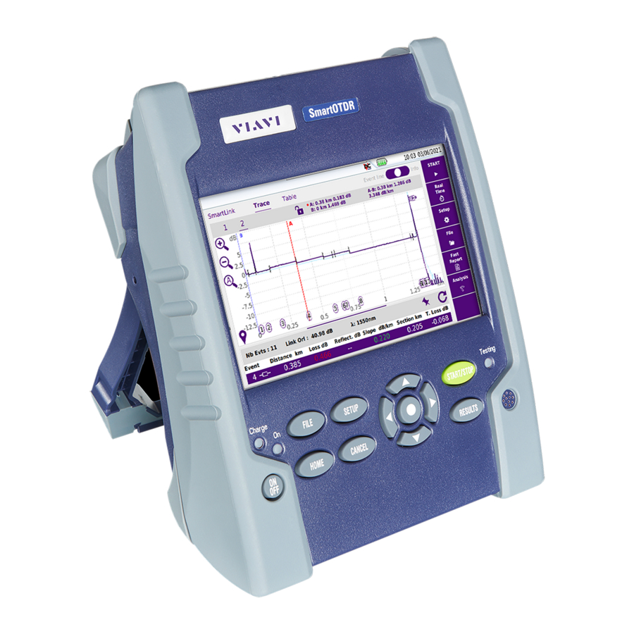
- Page 4 SmartOTDR OVERVIEW 18 19 5’’ HVT Capacitive Screen Direction & validation keys Charge indicator Results On indicator Buzzer File AC/DC Input Setup Mini USB port Start/Stop VFL connector Testing indicator USB ports (2) On/Off OTDR port/continuous light source / power meter...
- Page 5 CONFIGURING AN OTDR TEST IN SMART TEST MODE On the Home page, select Smart TEST icon Select the confi guration fi le corresponding to your application and press LOAD key. If necessary, modify some parameters before starting the measurement.
- Page 6 PERFORMING AN OTDR TEST IN SMART TEST MODE From the previous confi guration screen, press The measurement starts: Step1: Test port connection health check Step2: OTDR measurement At the end of the test, the Smart Link view is displayed, with a pop up window indicating global test results (loss, length at each wavelength, and alarm status).
- Page 7 RESULTS DISPLAY IN SMART TEST MODE Click on the tabs to display the result trace: Start: press to perform a new measurement. Real Time: press to perform a new measurement in Real Time. Assistant: press to return to Setup Information page (see “Confi guring a test in Smart Test Mode”, page 5).
- Page 8 CONFIGURING A TEST / CREATING A SMART CONFIG. IN EXPERT MODE On the Home page, select Expert OTDR icon From the Results page, press to confi gure the OTDR parameters. To create a confi guration, when all parameters are confi gured according to your test needs, press to save the current confi...
- Page 9 PERFORMING AN OTDR TEST IN EXPERT MODE Once the OTDR is confi gured, press to launch the measurement. Step1: Test port connection health check Step2: OTDR measurement At the end of test, the OTDR trace(s) or SmartLink View is displayed. Start: press to perform a new measurement in Expert mode Real Time: press to perform a new measurement in Real Time.
- Page 10 SAVING THE OTDR RESULTS IN EXPERT MODE In the Results screen, press Press on the relevant section to edit the Job ID, Cable Id and Fiber Number. Enter the location name for each fi ber extremity. Select the test direction. For bi-directional OTDR tests, don’t forget to change the direction.
-
Page 11: Technical Assistance
All the fi les and reports are saved and available in the defi ned directory. TECHNICAL ASSISTANCE If you require technical assistance, call 1-844-GO-VIAVI. For the latest TAC information, go to http://www.viavisolutions.com/en/services-and-support/sup- port/technical-assistance. SmartOTDR - Getting Started Manual - PN7SMART202 Rev003 - June 2021 - Copyright © 2021...
Need help?
Do you have a question about the SmartOTDR and is the answer not in the manual?
Questions and answers