Table of Contents
Advertisement
Quick Links
Advertisement
Table of Contents

Subscribe to Our Youtube Channel
Related Manuals for Viavi CT-X


Summary of Contents for Viavi CT-X
- Page 1 CT-X Advanced Leakage Tagger User’s Guide...
- Page 2 Copyright/Trademarks © Copyright 2020 VIAVI Solutions Inc. All rights reserved. No part of this guide may be reproduced or transmitted, electronically or otherwise, without written permission of the publisher. VIAVI Solutions and the VIAVI logo are trademarks of VIAVI Solutions Inc. (“Viavi”). All other trademarks and registered trademarks are the property of their respective owners.
- Page 3 VIAVI has established a take-back process in compliance with the EU Waste Electrical and Electronic Equipment (WEEE) Directive, 2012/19/EU. Instructions for returning waste equipment to VIAVI can be found in the WEEE section of the VIAVI Standards and Policies web page.
- Page 4 CT-X User’s Guide 22137813, Rev. 000 Feb 2020...
-
Page 5: Table Of Contents
Keyboard and menu conventions ..............9 Symbol conventions ..................9 Safety definitions ................... 10 Precautions ....................... 11 Periodic calibration ....................11 What ships with the CT-X? .................. 12 Preparation for use ....................12 Chapter 1 Quick Tour About the CT-X ....................... 14 Features ........................ - Page 6 CT-X setup........................24 Overview ......................24 Required equipment..................24 Locating positions for signals ..............25 Measuring metrics of adjacent channels ..........25 Setting up your CT-X .................... 27 Measuring adjacent channels ..............28 Example tag setup ..................29 Choosing signal locations ..............29 Measuring adjacent channels ............30 Injecting signals ...................31 Remeasuring adjacent channels .............
-
Page 7: About This Guide
About this Guide Thank you for purchasing the CT-X. This guide provides setup and operating instructions to get you up and running as soon as possible. Purpose and scope The purpose of this guide is to help you successfully use the product features and capabilities. -
Page 8: Safety And Compliance Information
A vertical bar | means “or”: only one option can appear in a single platform [a|b|e] command. Square brackets [ ] indicate an login [platform name] optional argument. Slanted brackets < > group <password> required arguments. CT-X User’s Guide 22137813, Rev. 000 Feb 2020... -
Page 9: Keyboard And Menu Conventions
This symbol represents a risk of a hot surface. It may be associated with either a DANGER, WARNING, CAUTION, or ALERT message. See the “Safety definitions” on page 10 for more information. CT-X User’s Guide Feb 2020 22137813, Rev. 000... -
Page 10: Safety Definitions
Indicates that there is an action that must be ALERT performed in order to protect equipment and data or to avoid software damage and service interruption. CT-X User’s Guide 22137813, Rev. 000 Feb 2020... -
Page 11: Precautions
Periodic calibration To maintain system accuracy and peak functionality, VIAVI recommends the CT-X is recalibrated every 2 years. Return the unit to VIAVI or a VIAVI authorized repair center for recalibration. CT-X User’s Guide Feb 2020 22137813, Rev. 000... -
Page 12: What Ships With The Ct-X
Safety information sheet Preparation for use This section explains how to start using the CT-X. When you unpack your instrument, do the following: Inspect the unit for damage. If the instrument is damaged, put it back in the box and contact VIAVI customer service (see “Technical assistance”... -
Page 13: Chapter 1 Quick Tour
This chapter provides an overview of the unit, status indicators, connectors, and user interface, including the following: “About the CT-X” on page 14 “Features” on page 14 “A guided tour of your CT-X” on page 15 “Navigating the menus” on page 16 CT-X User’s Guide Feb 2020... -
Page 14: About The Ct-X
X and existing detectors using a single CT-X transmitter. When several CATV systems operate in the same area, it is often difficult to determine which system is the source of a detected leak. The CT-X is designed to deal with the problem of leakage identification in overbuilt situations. -
Page 15: A Guided Tour Of Your Ct-X
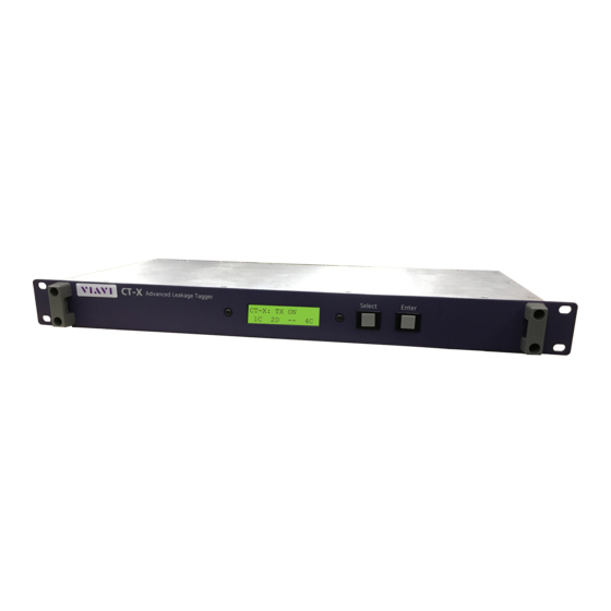
Chapter 1 Quick Tour A guided tour of your CT-X Front view 1. Display screen – Displays the setup and operational status. Most of the setup can be adjusted here using the front panel. 2. Select – Scrolls through the main menus, scrolls through the options in the submenus, and adjusts settings. -
Page 16: Navigating The Menus
Chapter 1 Quick Tour Navigating the menus The following sections show how to navigate the menus on the CT-X. Main menu MAIN MENU Upon startup, this screen appears Press the “Select” button to for approximately 10 seconds cycle through options INITIALIZING Press the “Enter”... -
Page 17: Status Menu
CT-X WEB: 1.0.18 Select NOTE: To change a setting in the menus, select ENTER to edit a setting, use SELECT to toggle the setting, and then press ENTER to confirm and exit. CT-X User’s Guide Feb 2020 22137813, Rev. 000... -
Page 18: Setup Menu
CONFIGURATION SETUP SIGNAL 4 Enter TO SIGNAL CONFIG CONFIGURATION SETUP MODE SETUP MODE Enter CHIRP STYLE CHIRP STYLE Enter DUAL CHAN STYLE DUAL CHAN STYLE Enter UNITS UNITS Enter dBmV dBuV Select CT-X User’s Guide 22137813, Rev. 000 Feb 2020... -
Page 19: Signal Configuration
SIGNAL N: FREQ SIGNAL N: FREQ 236.000000 MHZ 136.000000 MHZ Enter SIGNAL N: LEVEL SIGNAL N: LEVEL Enter +35.0 dBmV -10.0 dBmV CARRIER N: TYPE CARRIER N: TYPE Enter DUAL CARRIER CHIRP Select CT-X User’s Guide Feb 2020 22137813, Rev. 000... -
Page 20: Network Menu
SELECT: CONFIRM Enter DEFAULTS? ENTER: CANCEL Select Applicable fields are only configurable when in Static Press the “Select” addressing mode button to cycle through options SIGNAL N STATUS Enter CT-X User’s Guide SFP INFO 22137813, Rev. 000 Feb 2020 MNFR NAME... -
Page 21: Sfp Info
(ex. IP address is pulled while looking at the IP address screen) These “live update” pieces will be outlined in red, as shown below TITLE INFORMATION IPV6 2001:DB80 IPV6 Handling Ideas PREFIX 1234:152C CT-X User’s Guide Feb 2020 22137813, Rev. 000 IPV6 12B4:5678 HOST D334:9AF0... -
Page 22: System Menu
Chapter 1 Quick Tour SYSTEM MENU System menu LOAD FACTORY SELECT: CONFIRM SYSTEM MENU Enter DEFAULT? ENTER: CANCEL MAIN MENU RESET USERNAME SELECT: CONFIRM Enter AND PASSWORD? ENTER: CANCEL CT-X User’s Guide 22137813, Rev. 000 Feb 2020... -
Page 23: Setting Up Your Ct-X
This chapter provides an overview of how to configure and operate the unit, including the following: “CT-X setup” on page 24 “Setting up your CT-X” on page 27 “Remotely configuring your CT-X” on page 34 CT-X User’s Guide Feb 2020... -
Page 24: Ct-X Setup
Chapter 2 Setting up Your CT-X CT-X setup The CT-X injects a proprietary modulated or dual CW carrier tag across the entire downstream bandwidth in up to 4 locations (up to 4 signature tags with the proprietary modulated signal and 8 with the dual CW tag). -
Page 25: Locating Positions For Signals
LTE cellular, etc.)? If yes, it is best to avoid these regions as the meter will either not see the signal of the CT-X, or sensitivity will be compromised. Generally, the further away from such signals the better. - Page 26 Chapter 2 Setting up Your CT-X All measurements taken will have an unknown amount of loss between the transmitters (plant and CT-X) and the instrument, so all adjustments will be made to balance the two signal sources relative to each other.
-
Page 27: Setting Up Your Ct-X
Chapter 2 Setting up Your CT-X Setting up your CT-X In this section, we’ll configure the CT-X to transmit the signals at their appropriate frequencies and at recommended levels. You can use a spectrum analyzer to iteratively set the levels of each signal at their appropriate levels. -
Page 28: Measuring Adjacent Channels
Chapter 2 Setting up Your CT-X 6 – Sets the spacing to 937.5 Hz 7 – Sets the spacing to 1093.75 Hz 8 – Sets the spacing to 1250 Hz 7. Navigate to the UNITS menu and select the units (dBmV or dBµV). -
Page 29: Example Tag Setup
Chapter 2 Setting up Your CT-X Example tag setup Choosing signal locations There is a large quantity of Seeker D units deployed already, so we will put a dual CW tag at 138 MHz to support that group. There is also an OFDM channel from 810 to 906 MHz and that’s the highest frequency the plant generates, so we will put 3 Chirp tags at... -
Page 30: Measuring Adjacent Channels
Chapter 2 Setting up Your CT-X Measuring adjacent channels The channels adjacent to the soon-to-be-enabled signals were measured and the data is reflected below. Left channel Signal Right channel Power Freq Freq Power Freq (dB) (dBmV) (MHz) (MHz) (dBmV) (dB) (MHz) 25.4... -
Page 31: Injecting Signals
Injecting signals Based off the cable length, tap, and rated combiner loss, we expect there to be around 16 dB of loss between the CT-X and where we are measuring. From this, the following parameters are calculated: Desired level measured at instrument for each signal... -
Page 32: Remeasuring Adjacent Channels
To make sure we did not impair any adjacent channels, we will re-measure the adjacent channels to make sure nothing was impaired. First however, we must disable Setup mode to put the CT-X in its final transmit mode. Ethernet setup The CT-X NETWORK menu is used to adjust the Ethernet settings of the CT-X and for configuration through the web interface. -
Page 33: System Menu
Chapter 2 Setting up Your CT-X System menu The CT-X SYSTEM menu is used to reset the CT-X unit to factory defaults and reset the user name and password. To change a setting in the menus, select ENTER to edit a setting, use SELECT to toggle the setting, and then press ENTER to confirm and exit. -
Page 34: Remotely Configuring Your Ct-X
Chapter 2 Setting up Your CT-X Remotely configuring your CT-X Once you have your network set up through the front panel of the CT-X and you have an IP address, you can use the web interface to easily configure the unit remotely. -
Page 35: Administration Menu
Loading settings from a file Saving settings to a file Resetting the unit to factory defaults Rebooting the unit Select Reboot to reboot the CT-X. A pop-up asks you to confirm, click Reboot again and the device will restart. Updating the firmware If you have a firmware file from VIAVI, you can update your unit. -
Page 36: Loading Settings
Chapter 2 Setting up Your CT-X Loading settings If you have a settings file from VIAVI or from another unit, you can load the settings to your CT-X. Select Load settings from file, then select the settings file on your computer. -
Page 37: Saving Settings
Chapter 2 Setting up Your CT-X Saving settings You can copy the settings from one CT-X unit to another. Select Save settings to file, then navigate where you want to save the file on your computer. Resetting the factory defaults You can reset the unit to factory defaults, including all currents settings, network address, and login information. -
Page 38: Network Menu
Chapter 2 Setting up Your CT-X Network menu From the Network menu you can set up the Ethernet and SFP settings similarly to how you configure them from the front panel. You can also change the login information. See “Ethernet setup” on page 32 for more information. -
Page 39: Output Menu
Select the Output tab to bring up the Output menu. Adjust the settings as needed. When finished, select the Enable output checkbox and click Save to CT-X at the top. The settings will be saved to the CT-X. - Page 40 Chapter 2 Setting up Your CT-X CT-X User’s Guide 22137813, Rev. 000 Feb 2020...
-
Page 41: Appendix
This appendix includes troubleshooting and supplemental information, including the following: “Specifications” on page 42 “Error messages” on page 43 “Limited warranty” on page 44 “Technical assistance” on page 44 “Additional information” on page 44 CT-X User’s Guide Feb 2020 22137813, Rev. 000... -
Page 42: Specifications
Operating Temperature 32 to 104° F (0 to 40° C) Storage Temperature -4 to 140º F (-20 to 60° C) CT-X Operation Mode Compatibility Seeker X, Seeker D, and Seeker D Lite leakage detectors Carrier Types Chirp and dual CW digital leakage carriers... -
Page 43: Error Messages
FPGA file missing/unable to load FPGA CONFIG ERR FPGA failed to receive image PLL LOCK ERR PLL failed to lock DAC LINK ERR DAC JESD204B link failed to initialize CAL EXPIRED Calibration is out of date CT-X User’s Guide Feb 2020 22137813, Rev. 000... -
Page 44: Limited Warranty
Limited warranty For the latest warranty information, visit https://www.viavisolutions.com/literature/viavi-solutions-inc-general-terms-en.pdf https://www.viavisolutions.com/en-us/literature/viavi-manufacturer-warranty-nse- products-en.pdf Technical assistance If you require technical assistance, call 1-844-GO-VIAVI / 1.844.468.4284. For the latest TAC information, visit http://www.viavisolutions.com/en/services-andsupport/support/technical-assistance Additional information For more detailed information, contact us at for these Trilithic.support@viavisolutions.com... - Page 46 22137813 Rev. 000, Feb 2020 English VIAVI Solutions North America 1.844.GO VIAVI / 1.844.468.4284 Latin America +52 55 5543 6644 EMEA +49 7121 862273 APAC +1 512 201 6534 All Other Regions viavisolutions.com/contacts email Trilithic.support@viavisolutions.com...
Need help?
Do you have a question about the CT-X and is the answer not in the manual?
Questions and answers