Table of Contents
Advertisement
Advertisement
Table of Contents

Related Manuals for Viavi Certifier40G


Summary of Contents for Viavi Certifier40G
- Page 1 CERTIFIER40G Fiber Certification Testing User Manual...
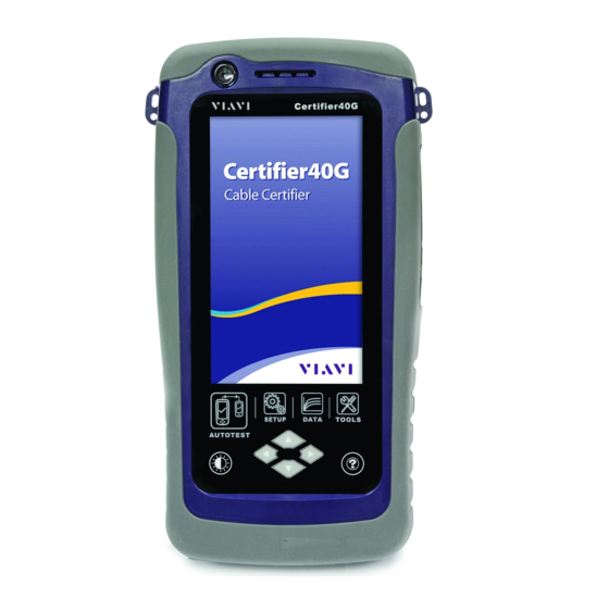
- Page 2 Certifier Series (C40G)
- Page 3 Viavi Solutions shall not be liable for errors or for incidental or consequential damages in connection with the furnishing, use, or performance of this document or of any information contained herein.
-
Page 4: General Safety Information
Operating humidity 20% to 85% RH non-condensing Relative humidity 10% to 80% NOTE The CERTIFIER40G, CERTIFIER10G complies with the following Safety and Regulatory requirements. DIN EN 55024, Edition:2003-10 (IEC/CISPR 24:1997, modified + A1:2001 + A2:2002); EN 55024:1998 + A1:2001 + A2:2003... - Page 5 DIN EN 55022; VDE 0878-22:2008-05 (IEC/CISPR 22:2005, modified + A1:2005); EN 55022:2006 + A1:2007 Regulatory Markings The CE mark is a registered trademark of the European Community. This CE mark shows that the product complies with all the relevant European Legal Directives.
-
Page 6: Declaration Of Conformity
Declaration of Conformity Manufacturer‘s Name Psiber Data Pte. Ltd Manufacturer’s Address 3 Science Park Drive #03-08, The Franklin Singapore Science Park 1, Singapore 118223 Declares under sole responsibility that the product as originally delivered Description Cable Certification Tester Kit Equipment Cable Certifier Complies with the essential requirements of the following applicable European Directives and carries the CE marking accordingly:... -
Page 7: Table Of Contents
Contents Chapter 1: Getting Started ........................8 Unpacking the box ........................8 Chapter 2: Configuring Certifier ....................... 10 Certifier User Interface ........................ 10 Touch Screen Layout ......................10 The One Touch Access Buttons ....................12 Chapter 3: Setting Reference ......................21 Chapter 4: Configuring an AUTOTEST .................... -
Page 8: Chapter 1: Getting Started
Chapter 1: Getting Started Unpacking the box Single Mode Fiber Single Mode Adapters SC-SC Duplex Reference Cords Mating Coupler Multi Mode Fiber Multi Mode Adapters SC-SC Duplex Reference Cords Mating Coupler... - Page 9 Encircled Flux Compliant Multi Mode Fiber EF Compliant MM Adapters FC-SC Modally Transparent Reference Cords SC-SC Tail Cords Mating Coupler Optional SM/MM/MMEF LC Cord Kits available.
-
Page 10: Chapter 2: Configuring Certifier
Chapter 2: Configuring Certifier Certifier User Interface Touch Screen Layout The Graphical User Interface (GUI) in version 7.0’s firmware has been updated with a more responsive system and quick-access menus. Certifier boots up to the SETUP screen. It is categorised into 5 groups: 1. -
Page 12: The One Touch Access Buttons
1. The Status bar displays the current date, talk set and battery level. 2. The Configuration group provides selection on number of jumper(s) referencing is set to, and determine single or bi-directional test is performed during an AUTOTEST. 3. The Test Settings group provides results oriented configurations necessary to perform an AUTOTEST. - Page 13 SM Fiber AUTOTEST results Detailed results for 1310nm Detailed results for 1550nm MM Fiber AUTOTEST results Detailed results for 850nm Detailed results for 1310nm...
- Page 14 MMEF Fiber AUTOTEST results Detailed results for 850nm Detailed results for 1300nm If Bi-direction is selected, swap the TX and RX connections on both ends when prompted. Swapping of TX and RX for Swapping of TX and RX for Single-ended loopback Dual-ended testing.
- Page 15 1 Jumper, Single-ended 1 Jumper, Dual-ended 2 Jumpers, Single-ended 2 Jumpers, Dual-ended 3 Jumpesr, Single-ended 3 Jumpers, Dual-ended According to the ISO/IEC standards, the 2-jumpers testing method is not compliant, hence the selection for 2-jumpers configuration will be disabled when an ISO limit is selected.
- Page 16 Test Settings Test Settings provides results oriented configurations necessary to perform an AUTOTEST. Test Limit Standard Limits: Choose from a list of standards to determine the performance criteria in a given standard. Tab to change the value for number of connections, loss per connection, number of splices and loss per splice.
- Page 17 Cable Press the SETUP button > Test Settings > Cable to choose from a list of cable manufacturers. If unsure of manufacturer, choose “Generic SMF” or “Generic MMF”, or “Customised Cable” to create custom cable. Click “Add” to add or “Manage” to remove customised cable(s) from the customised cable list. Add customised cable Manage customised cables When creating customised cable, determining the cable name, cable type, performance grade...
- Page 18 operators, customized cables, customized connectors and results to be selected and deleted simultaneously. Refractive Index The refractive index determines the speed light is travelling in the fiber optic. The value is determined by the fiber cable selected. Modal Bandwidth Press the SETUP button > Test Settings > Modal Bandwidth to choose the modal bandwidth of the cable under test.
- Page 19 Project Settings Project Settings provides non-results oriented configurations before performing an AUTOTEST. Refer to User Manual – Certifier Copper Certification for more information on Project Settings. Label Source Refer to User Manual – Certifier Copper Certification or User Guide – List Based Testing for more information.
- Page 20 View results Manage results TOOLS The “TOOLS” button provides advanced options for in-depth troubleshooting and advanced Certifier users. These options include- Requires: Requires: Requires: Local and Remote Local and Remote Local or Remote Set Reference – Establish test Power Meter –Measures the Light Source –...
-
Page 21: Chapter 3: Setting Reference
Chapter 3: Setting Reference It is necessary to perform a set reference measurement at the beginning of a job, whenever the test fiber is disconnected from the transmitter, and whenever a reference verification fails. The setup varies depending on the number of jumpers reference is selected. Following procedures are only for MMEF, MM and SM fiber. - Page 22 5. Check that the Set Reference result is ≤0.15 dB before proceeding. Clean or replace reference cords if necessary, and set reference again if value exceeds 0.15 dB. Verification Test To verify reference has been set correctly, setup the following connection. 1.
- Page 23 4. Connect SC3 to the Remote RX port and SC4 to coupler 1. 5. Press the AUTOTEST button. 6. Check that the result passes with the following results; Single Mode – 0.2 dB Multi-Mode - 0.1 dB EF compliant Multi-mode – 0.1 dB For 2 jumpers dual-ended, 1.
- Page 24 6. Press the TOOLS button > Set Reference and press the “ok” button to begin set reference. 7. Check that the Set Reference result is ≤0.15 dB before proceeding. Clean or replace reference cords if necessary, and set reference again if value exceeds 0.15 dB.
- Page 25 For 3 jumpers dual-ended, 1. Connect FC1 to the Local TX port and SC1 to coupler 1. 2. Connect SC5 to the Local RX port and SC6 to coupler 2. 3. Connect FC2 to the Remote TX port and SC2 to coupler 4. 4.
- Page 26 For 1 jumper single-ended loopback, 1. Connect the FC and SC ends of the reference cord to the TX port RX port of the adapter respectively. Please ensure the fiber cables are cleaned using the cleaning kit provided in the kit. 2.
- Page 27 For 2 jumpers single-ended loopback, 1. Connect FC1 to the TX port and SC1 to a SC coupler. 2. Connect SC2 to the RX port and SC3 to the coupler. Please ensure the fiber cables are cleaned using the cleaning kit provided in the kit. 3.
- Page 28 For 3 jumpers single-ended loopback, 1. Connect FC1 to the TX port and SC1 to a SC coupler 1. 2. Connect SC2 to the RX port and SC3 to another coupler 2. 3. Connect your jumper’s SC end SC4 to coupler 1 and SC5 to coupler 2. Please ensure the fiber cables are cleaned using the cleaning kit provided in the kit.
- Page 29 Adapter probe mismatch Firmware version mismatch No connection between Local and Remote units According to the ISO/IEC standards, the 2-jumpers testing method is not a recognised procedure, hence the selection for 2-jumpers configuration will be disabled when an ISO limit is selected.
-
Page 30: Chapter 4: Configuring An Autotest
Chapter 4: Configuring an AUTOTEST After configuring the system settings, follow these steps to set up an AUTOTEST. 1. Press the SETUP button > Project Settings a. Site – Create or select a Site b. Operator – Create or select an Operator c. -
Page 31: Testing Guide For Dual-Ended Testing
Testing Guide for Dual-Ended Testing 1. Connect FC1 to the Local TX port and SC1 to coupler 1. 2. Connect SC5 to the Local RX port and SC6 to coupler 2. 3. Connect FC2 to the Remote TX port and SC2 to coupler 4. 4. -
Page 32: Testing Guide For Single-Ended Loopback Testing
10. Select “850nm” or “1300nm” for Multi-mode or “1310nm” or “1550nm” for Single Mode to check the Loss, Limit and Margin of the fiber setup at the respective wavelength. Testing Guide for Single-Ended Loopback Testing 1. Connect FC1 to the Local TX port and SC1 to coupler 1. 2. - Page 33 9. Select “850nm Margin” or “1310nm Margin” to check the Loss, Limit and Margin of the fiber setup at the respective wavelength.
-
Page 34: Chapter 5: Performing An Autotest
Chapter 5: Performing an AUTOTEST Press the AUTOTEST button once settings and limits have been selected. Certifier will use the last configuration or factory settings to perform the AUTOTEST if new settings are not configured. Certifier will display summarized result with PASS or FAIL once AUTOTEST is completed. Press the “View”... -
Page 35: Managing Test Result(S)
Certifier will perform a separate test based on the loss value input if Link Validation is selected. Managing test result(s) Test results can be manually saved by pressing the “Save” button after an AUTOTEST is completed. When prompted, enter label name and click “OK” to save. The “Save”... -
Page 36: Exporting Test Results Into J-Report Pc Software
Exporting test results into J-Report PC Software Refer to User Manual – Certifier Copper Certification for more information on exporting test results into J-Report PC Software. Refer User Manual – J-Report for more information on how to use the software.
Need help?
Do you have a question about the Certifier40G and is the answer not in the manual?
Questions and answers