
Related Manuals for Viavi SmartOTDR 100


Summary of Contents for Viavi SmartOTDR 100
- Page 1 SmartOTDR 100 Mainframe Handheld OTDR, designed for the construction, turn-up and maintenance of fiber networks User Manual...
- Page 3 SmartOTDR 100 Mainframe Handheld OTDR, designed for the construction, turn-up and maintenance of fiber networks User Manual Viavi Solutions 1-844-GO-VIAVI www.viavisolutions.com...
- Page 5 In the European Union, all equipment and batteries purchased from Viavi after 2005-08-13 can be returned for disposal at the end of its useful life. Viavi will ensure that all waste equipment and batteries returned are reused, recycled, or disposed of in an environmentally friendly manner, and in compliance with all applicable national and international waste legislation.
- Page 6 It is the responsibility of the equipment owner to return equipment and batteries to Viavi for appropriate disposal. If the equipment or battery was imported by a reseller whose name or logo is marked on the equipment or battery, then the owner should return the equipment or battery directly to the reseller.
-
Page 7: Table Of Contents
Table of Contents About This Guide Purpose and scope......... xvi Assumptions . - Page 8 Table of Contents ....... 15 Connecting the mains adapter ........15 First use of the battery .
- Page 9 Table of Contents VFL Function ..........42 .
- Page 10 ..... . 83 Downloading the Viavi application on PC ..85 Downloading the Viavi application on Tablet/Smartphone .
- Page 11 Table of Contents Directories and Files selections ......106 ........106 Directory selection .
- Page 12 ......141 Checking new upgrade on Viavi Server ....... . .141...
- Page 13 Table of Contents ........142 Install Software License .
- Page 14 Table of Contents User Manual 7SMART102 Rev004...
-
Page 15: About This Guide
About This Guide The SmartOTDR of Viavi provides a handheld OTDR designed for the construction, turn- up and maintenance of fiber networks. The topics discussed in this chapter are as follows: • “Purpose and scope” on page xvi • “Assumptions” on page xvi •... -
Page 16: Purpose And Scope
This guide includes task-based instructions that describe how to install, configure, use, and troubleshoot the SmartOTDR. Additionally, this guide provides a complete description of Viavi’s warranty, services, and repair information, including terms and conditions of the licensing agreement. Assumptions This guide is intended for novice, intermediate, and experienced users who want to use the SmartOTDR effectively and efficiently. - Page 17 About This Guide Conventions Table 1 Typographical conventions Description Example Code and output messages appear in All results okay this typeface. Text you must type exactly as shown Type: in the dialog box a:\set.exe appears in this typeface. Variables appear in this typeface. Type the new hostname Book references appear in this typeface.
- Page 18 About This Guide Conventions NOTE This symbol represents a Note indicating related information or tip. This symbol, located on the equipment or its packaging indicates that the equipment must not be disposed of in a land-fill site or as municipal waste, and should be disposed of according to your national regula- tions.
-
Page 19: Chapter 1 Safety Information
Safety information Chapter 1 This chapter gives the main information on the safety conditions when using the Smar- tOTDR: • “Battery and AC/DC safety information” on page 2 • “Precautions relating to optical connections” on page 3 • “Laser Safety instructions” on page 3 User Manual 7SMART102 Rev004... -
Page 20: Battery And Ac/Dc Safety Information
• Do not use any mains adaptor or battery other than those supplied with the instru- ment, or supplied by Viavi as an option for this instrument. If another adapter or battery is used, it may damage the SmartOTDR itself. -
Page 21: Precautions Relating To Optical Connections
Chapter 1 Safety information Precautions relating to optical connections Other basic safety precautions are as follows: • Do not use AC/Adapter/Charger outdoors or in wet or damp locations • Connect the AC/Adapter/Charger to the correct mains voltage, as indicated on the ratings label. -
Page 22: Laser Classes
Chapter 1 Safety information Laser Safety instructions • FDA 21 CFR § 1040.10 - Performance standards for light-emitting products - Laser products. Due to the range of possible wavelengths, power values and injection characteristics of a laser beam, the risks inherent in its usage vary. The laser classes form groups repre- senting different safety thresholds. -
Page 23: Introducing The Smartotdr
Introducing the SmartOTDR Chapter 2 This chapter provides a general description of the SmartOTDR. Topics discussed in this chapter include the following: • “Unpacking the instrument” on page 6 • “Main features” on page 6 • “Hard keys and Indicators” on page 9 •... -
Page 24: Unpacking The Instrument
Remove the SmartOTDR and its accessories from the packing case. Check that the correct model and accessories ordered are all there. If any part is missing or damaged please contact your local Viavi agent. The SmartOTDR is delivered as standard with:... - Page 25 Chapter 2 Introducing the SmartOTDR Main features • Open all user documentations included into the SmartOTDR • Update the SmartOTDR firmware • Remote the screen of the SmartOTDR onto a PC and issue commands from the keyboard of the PC •...
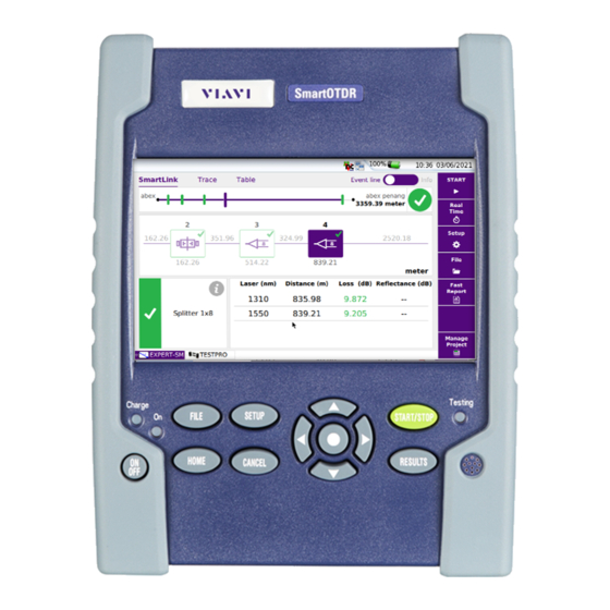
- Page 26 Chapter 2 Introducing the SmartOTDR Main features Figure 2 SmartOTDR: Front view 5’’ Color Capacitive Touchscreen Indicators Buzzer Hard keys Figure 3 SmartOTDR: Connectors View Mini USB AC/DC USB host + OTDR port + device Input Power Meter (see Power Meter (see OTDR Chapter application User Manual) User Manual...
-
Page 27: Hard Keys And Indicators
Chapter 2 Introducing the SmartOTDR Hard keys and Indicators Hard keys and Indicators Front panel hard keys Figure 4 Hard keys and Indicators Table 6 Hard keys description Hard key Function Main on/off switch This button calls up the file explorer. It allows to: •... -
Page 28: Front Panel Indicators
Chapter 2 Introducing the SmartOTDR Hard keys and Indicators The direction keys have two principal functions: • on the Results page, they are used to move the cursors or modify the zoom factor. • on the set-up pages, they are used to scroll through the menus, the central button serving to select or confirm the parameter chosen. -
Page 29: Power Supply
Chapter 2 Introducing the SmartOTDR Power Supply Power Supply The SmartOTDR may operate with • the Li-Polymer battery or the AA dry battery pack (according to what has been ordered) or a AA dry battery pack (according to the order placed). •... - Page 30 Chapter 2 Introducing the SmartOTDR Power Supply User Manual 7SMART102 Rev004...
-
Page 31: Starting Up
Starting up Chapter 3 This chapter describes the first steps to perform when using the SmartOTDR. The topics discussed in this chapter are as follows: • “Setting the adaptable plug to the mains adapter” on page 14 • “Charging the battery” on page 15 •... -
Page 32: Setting The Adaptable Plug To The Mains Adapter
Chapter 3 Starting up Setting the adaptable plug to the mains adapter Setting the adaptable plug to the mains adapter The SmartOTDR is supplied as standard with a mains adapter and 5 country adaptable plugs (Europe / UK / US / Australia/Japan). To set the correct plug to the mains adapter: Make flush the connector onto the mains adapter with the adaptable plug slots. -
Page 33: Charging The Battery
Chapter 3 Starting up Charging the battery Charging the battery CAUTION Upon reception of the product, the battery of the SmartOTDR needs to be fully recharged, no later than 6 months after the date of calibration. If the product is unused for a long period, the battery needs also to be periodically fully recharged, with a period not longer than 12 months Connecting the mains adapter Set the appropriate adaptable plug to the power supply cable, according to your... -
Page 34: Charging The Li-Polymer Battery
Chapter 3 Starting up Charging the battery NOTE If a AA Dry Battery pack is used, fully charge the batteries before setting the pack into the SmartOTDR. Charging the Li-Polymer battery On connection to the mains: • if the user does not press , the battery will start the charge. -
Page 35: Switching The Smartotdr On And Off
If the equipment is powered to mains, the battery will charge. The On indicator pass from blinking to solid green. The Viavi logo appears on the screen briefly, then an auto test is carried out. The equipment is ready to be used once all the applications are installed. -
Page 36: Switching Off The Smartotdr
Chapter 3 Starting up Choosing the position of the instrument on the work surface In the event of an unexpected mains power cut, if there is no battery, the current results and configuration will not be saved. Next time the instrument is switched on, it will return to its initial configuration. -
Page 37: First Start: Configuring The Regional Settings
Chapter 3 Starting up First start: configuring the regional settings Figure 7 SmartOTDR «seated» and «standing» user positions Stand Pull to lift the stand First start: configuring the regional settings Once the SmartOTDR is switched on, the first screen displayed allows to configure the regional settings. - Page 38 Chapter 3 Starting up First start: configuring the regional settings Click on Language and select the language to be used for the equipment. Click on Date and enter the current date, using the numeric keypad displayed using the menu key Edit Number. Click on Time and enter the current time, using the numeric keypad displayed using the menu key Edit Number.
-
Page 39: Configuring The Smartotdr
Configuring the SmartOTDR Chapter 4 This chapter describes the operations for configuring the instrument. The topics discussed in this chapter are as follows: • “Displaying the System Settings screen” on page 22 • “Defining the screen parameters of the SmartOTDR” on page 23 •... -
Page 40: Displaying The System Settings Screen
Chapter 4 Configuring the SmartOTDR Displaying the System Settings screen Displaying the System Settings screen To display the System Settings screen, you must: Press the H hard key to reach the Home page. Figure 9 Home page Activate the Settings icon to open the System Settings screen. -
Page 41: Defining The Screen Parameters Of The Smartotdr
Chapter 4 Configuring the SmartOTDR Defining the screen parameters of the SmartOTDR Defining the screen parameters of the SmartOTDR In the System Settings page, the following parameters can be defined: Backlight Click on Backlight Define the backlight level of the screen, using the left and right direction keys, or clicking on Edit Number softkey and using the keypad displayed. -
Page 42: Screen Saver
Chapter 4 Configuring the SmartOTDR Defining the Automatic shutdown and the type of batteries Screen Saver Click on Screen Saver if you wish to activate a screen saver to the equipment, to extend the life of the battery/AA dry battery pack, in case the SmartOTDR is not used for some time. -
Page 43: Type Of Batteries
Chapter 4 Configuring the SmartOTDR Defining the Automatic shutdown and the type of batteries Type of batteries When a AA Dry battery pack is used to work on the SmartOTDR, the type of batteries can be defined on the System Settings page: either NiMH (rechargeable) batteries or Alkaline batteries. - Page 44 Chapter 4 Configuring the SmartOTDR Defining the Automatic shutdown and the type of batteries User Manual 7SMART102 Rev004...
-
Page 45: Optical Options
Optical options Chapter 5 A variety of built-in optical options are available when ordering. See references in Chapter 10 “Options and accessories”, for details. The topics discussed in this chapter are as follows: • “Connection to the power meter and VFL” on page 28 •... -
Page 46: Connection To The Power Meter And Vfl
Chapter 5 Optical options Connection to the power meter and VFL Connection to the power meter and VFL Figure 13 Optical connectors Power meter optical connection via OTDR port (see OTDR User Manual) Power meter optical connection via USB (see below) •... -
Page 47: Configuring The Alarm Parameters
Chapter 5 Optical options Using the Power meter via USB port Figure 14 Configuration of power measurement Configuring the alarm parameters Alarm Activation of the Alarm function: any result below the lower threshold or above the upper threshold will be displayed in red on the Results page. -
Page 48: Configuring The Link Parameters
Chapter 5 Optical options Using the Power meter via USB port Wavelength Select wavelength: Auto: the wavelength of the input signal will be automatically detected and selected to perform the measurement: 1310, 1490, 1550, 1625 or 1650 nm: measurement performed at specified wavelength. - Page 49 Chapter 5 Optical options Using the Power meter via USB port NOTE The softkey Copy File/Link To all is displayed when one parameter is selected in the Link or File Setup page and when the Powermeter function is active at the same time as another FO application (for example OTDR Expert).
- Page 50 Chapter 5 Optical options Using the Power meter via USB port Min: -999 / Max: 999 / Auto: 0 the Fiber number must not automatically modified. Cable Id This parameter allows to enter an identification of the cable, using the Edition menu. Direction The direction shows if the acquisition has been made from the origin to the extremity (A- >B) or from the extremity to the origin (B->A).
-
Page 51: Configuring The File Parameters
Chapter 5 Optical options Using the Power meter via USB port Configuring the File parameters The File storage parameters must be also configured, in order to define how the results will be saved on to the SmartOTDR. In the Setup page, press File soft key (if one parameter is selected in the current screen, press Top Menu soft key to display the right menu keys and click on File). - Page 52 Chapter 5 Optical options Using the Power meter via USB port Fig. 15 Directory - Edition keypad Press Auto Naming to apply the name by default to the directory: disk/[Cable_Id] Press Clear and validate (Enter key) in order to define the [Current directory] selected as directory for saving measurements.
- Page 53 Chapter 5 Optical options Using the Power meter via USB port Figure 16 Filenaming - Edition keypad (Auto) Press Default Filename to apply the name by default to the file: Fiber[Cable_Id][Fiber_Num]_[Lambda]_[Direction] The name of the file is displayed in grey under Filenaming parameter. Report Configuration The powermeter results file can be saved with or without a report according to the config- uration defined.
-
Page 54: Saving Configuration In A File
Chapter 5 Optical options Using the Power meter via USB port Saving configuration in a file Once File and Measurement parameters have been configured, those parameters can be kept in memory and saved in a configuration file. This configuration file can then be recalled in order to be applied when powermeter measurements are performed. -
Page 55: Loading An Existing Lts Configuration
Chapter 5 Optical options Using the Power meter via USB port Loading an existing LTS configuration To load a configuration file previously created or available in the T-BERD/MTS/ Smar- tOTDR and apply parameters to new Powermeter tests: From the File Explorer page Press F hard key Select the configuration file desired. -
Page 56: Display Of Results And Commands
Chapter 5 Optical options Using the Power meter via USB port Fig. 18 Loading a configuration file Display of results and commands The results page called up by the button gives the information relating to the ESULTS measurement in progress, results previously saved and the commands available for measurement and saving. -
Page 57: Commands Of The Power Meter Parameters
Chapter 5 Optical options Using the Power meter via USB port • A measurement result is displayed in the table when the Keep Result soft key is pressed. • Clear Table soft key deletes all the results displayed in the table. •... -
Page 58: Performing A Measurement
Chapter 5 Optical options Using the Power meter via USB port If the Source function is selected (either on this Platform / base Unit or on an OTDR module), the Power meter results page is different: • The choice of Wavelength, Unit and Zero menu keys are accessible via the menu key Power Config.. -
Page 59: Combo Powermeter/Otdr
Chapter 5 Optical options Using the Power meter via USB port In the Results page, press the Powermeter Config. > Zero soft key and vali- date. Carrying out the reference measurement (1-jumper reference) Fix the adapter corresponding to the jumper to the optical connector of the power meter. -
Page 60: Vfl Function
Chapter 5 Optical options VFL Function Figure 20 Combo Powermeter / OTDR CAUTION Only the following SmartOTDR used in combination with the powermeter, have the Combo PM/OTDR function; E117FA65PPM-PC, E117FA65PPM- APC, E136FB-PC and E136FB-APC. VFL Function VFL connector The type of optical connector used for the VFL source is UPP (Universal Push Pull), which is compatible with all diameter 2.5 mm connectors (FC, SC, ST, DIN, E2000, etc.) Figure 13 on page 28 to visualize the VFL connector. -
Page 61: Storing And Reloading Results
Chapter 5 Optical options Storing and reloading results NOTE Identification is facilitated by the blinking of light in the fiber. To emit a light signal into a fiber: Connect the fiber to the VFL port on the connectors panel. Press the key and activate the VFL The icons display on the upper banner of the screen. - Page 62 Chapter 5 Optical options Storing and reloading results User Manual 7SMART102 Rev004...
-
Page 63: Scope
Scope Chapter 6 The scope function is a hot-plug feature enabled directly when inserting a Viavi scope supplied as an accessory (see Chapter 10): The topics discussed in this chapter are as follows: • “Scope feature” on page 46 •... -
Page 64: Scope Feature
Chapter 6 Scope Scope feature Scope feature Overview This feature enables you to verify that your optical connectors are in perfect shape and very clean condition. The P5000i Digital Probe Microscope and the FiberCheck Probe are a portable hand- held microscope used to view and inspect both the bulkhead (female) and patch cord (male) sides of fiber connectors as well as other optical devices, such as transceivers. -
Page 65: Installation Of Tips
Seven tips, patchcords and bulkheads types, are delivered with the Videoscope Kit (ESDFSCOPE5Ki) but many others can be used. Configuring the Scope P5000i Scope connection Plug in your Viavi scope into a USB port from the SmartOTDR. Push the button Home User Manual 7SMART102 Rev004... -
Page 66: Fibercheck Scope Connection
Chapter 6 Scope Configuring the Scope Validate the Scope function Connect probe with the fiber being inspected. You may select this option while other options are already selected (e.g. OTDR). FiberCheck Scope connection WIFI Connection Turn on the scope. Make sure the WIFI connection is activated onto the Scope (see FiberCheck User manual). -
Page 67: Usb Connection
Chapter 6 Scope Configuring the Scope USB Connection Link the scope to the SmartOTDR using a mini-USB cable. Figure 24 WIFI connection of the FiberCheck Scope to the SmartOTDR Turn on the scope. On the SmartOTDR, press the H button. Validate the Fiber Microscope icon You may select this option while other options are already selected (e.g. -
Page 68: Analysis
Chapter 6 Scope Configuring the Scope Figure 25 P5000i Scope Setup Analysis Profile On the line Profile, select the Profile which will be used for the test of fiber connector: • SM_UPC Pass/Fail criteria for single-mode UPC connectors from IEC 61300-3-35 standard. -
Page 69: Link
Chapter 6 Scope Configuring the Scope Capture button This parameter allows to select the action of the Quick Capture button onto the Scope (see Figure 21 on page 46 Figure 22 on page 47): • Freeze & Test pressing the button will automatically perform a test of fiber and freeze the result •... -
Page 70: File
Chapter 6 Scope Configuring the Scope Increment; the fiber number is automatically incremented at each results saving Decrement: the fiber number is automatically decremented at each results saving. User Defined: Use the menu key Edit Number to enter the value for incrementa- tion / decrementation of the fiber number. - Page 71 Chapter 6 Scope Configuring the Scope In the edition keypad, select the pre-defined parameters available or, press abc key to enter a name manually for the directory. Then, press Enter to validate. Example: disk/Scope results Fig. 26 Directory - Edition keypad Press Clear and validate (Enter key) in order to define the [Current directory] selected as directory for saving measurements.
-
Page 72: Managing Scope Profiles
Chapter 6 Scope Configuring the Scope Figure 27 Filenaming - Edition keypad (auto) Press Default Filename to apply the automatic name to the file: Fiber[Cable_Id][Fiber_Num]_[Direction] Below Filenaming, the name of the file is displayed. Logo Click on right arrow key and select in the Explorer a JPG file which will represent the Logo displayed on the upper left part of the report Save mode Select if the test results must be saved only in an Image, only in a pdf Report or in an... -
Page 73: Defining The Profiles Available On The Setup Screen
Chapter 6 Scope Configuring the Scope Defining the profiles available on the Setup screen Once in the Setup page of the Scope application: Select the Profile parameter to open the sub-menu In the right menu keys, press Manage. From the Profiles list, click on one profile (in video reversed) and press Select / Unselect menu keys to add or remove this profile to/from the sub-menu of the Setup screen Directly click on the check box of the profile to select/deselect it. -
Page 74: About Page
Chapter 6 Scope Starting up with the scope Select the profile just loaded. Press Top Menu to return to Setup screen and select the profile just added. About page On the Setup screen, the softkey About, on the right of the screen, allows to display information on scope and current test result displayed (in Full Screen mode or mosaic mode - see “Mosaic Mode”... -
Page 75: Freeze Mode
Chapter 6 Scope Starting up with the scope Figure 30 Example of the result using the P5000i scope Sharpness level Use the Focus Control button onto the scope (see Figure 21 on page 46 Figure 22 on page 47) to adjust the image quality and sharpness. NOTE To switch from Scope page to FO results page and vice-versa, press the hard key for about 2 seconds (a beep is emitted). -
Page 76: High Mag. / Low Mag
Chapter 6 Scope Launching a test of the connector and fiber end-face High Mag. / Low Mag. The High Mag./Low Mag. menu key allows to switch the display from High to Low magnification and vice-versa. This function is also available pressing the button directly on the scope (see Figure 21 on page 46 Figure 22 on page... -
Page 77: Overlay
Chapter 6 Scope Launching a test of the connector and fiber end-face Figure 31 Test results Profile selected in the Setup page Summary of Test results Test result in High mag. A summary of test results is displayed on the right, upper part of the screen. •... -
Page 78: Mosaic Mode
Chapter 6 Scope Launching a test of the connector and fiber end-face When the key is deselected, the zones and defaults are not graphically identified. This function is also available in Mosaic Mode (see “Mosaic Mode” on page 60). Mosaic Mode It is possible to display only one picture in full screen (640 * 390 pixels) or up to four pictures (320*180 pixels each, including the live camera picture) in mosaic mode. - Page 79 Chapter 6 Scope Launching a test of the connector and fiber end-face Freeze The live picture from the camera is frozen but does not replace the live picture at position 1. The new snapshot is placed at the second position, and all existing pictures are pushed to the next position. If all positions were taken, the picture that was once at the fourth position is unloaded from memory.
-
Page 80: Loading A Picture
Chapter 6 Scope File menu Loading a picture It is possible to retrieve and load a picture stored in the Scope directory and display it in the Scope page. Press the button. Select the JPEG file to be loaded via the Explorer Click on Load Recognized pictures are images resulting from the Scope option and saved on disk via the SmartOTDR. -
Page 81: Display Of The Report
Chapter 6 Scope File menu Display of the report Once the report has been generated: Press F hard key. In the File Explorer, select the pdf report just created. Press Load. Figure 33 PDF report of Scope test result Parameters selected in the Setup page (see “Configuring the Scope”... - Page 82 Chapter 6 Scope File menu User Manual 7SMART102 Rev004...
-
Page 83: Connectivity
Connectivity Chapter 7 This chapter describes the different ways to access to the SmartOTDR interface or content using different connection modes. Topics described in this chapter are as follows: • “Establishing connection” on page 66 • “Remote Control” on page 81 •... -
Page 84: Establishing Connection
Chapter 7 Connectivity Establishing connection Establishing connection Via Bluetooth The Bluetooth interface allows interface and file transfers. It is an option that must be installed at the factory. The product is approved in accordance to R&TTE directive concerning transmitter module marked by CE0678. It is manufactured by MITSUMI and it is an OEM product. -
Page 85: Pairing The Platform With A Device
Chapter 7 Connectivity Establishing connection Figure 34 View board and connectors Insert the Bluetooth into the connector of the board. Figure 35 Bluetooth set into the Platform Screw back the cover onto the Platform Restart the SmartOTDR, pressing O button. The Bluetooth option can be launched. - Page 86 Chapter 7 Connectivity Establishing connection The following screen displays Figure 36 Bluetooth disabled Press the menu key Bluetooth to enable the Bluetooth interface. The icon is displayed on the upper banner of the screen The Paired Bluetooth Devices screen appears Press the Become Pairable soft key to wait for another device to initiate the connection to the SmartOTDR.
-
Page 87: Searching New Devices To Be Paired With The Platform
Chapter 7 Connectivity Establishing connection If you are asked to, validate a pairing code on the equipment. In this case, validate the pairing code on both equipments. Both equipment are now paired: Figure 38 Platform paired with one equipment The icon has a blue background when paired with a device , versus no back- ground when not paired Searching new devices to be paired with the... -
Page 88: Removing The Pairing
Chapter 7 Connectivity Establishing connection Figure 39 List of devices found Select the device to be paired with the Platform It will be underlined in blue. Push the Pair key to connect the device to the Platform If prompted, enter a pairing code. The code must be identical on the SmartOTDR and the device. -
Page 89: Via Wifi
Chapter 7 Connectivity Establishing connection Via Wifi The WIFI application is available on option with the SmartOTDR, ref E10WIFI. Installation of the WIFI option in the Platform The WIFI option is delivered on a USB key to be connected to the WIFI board which will be inserted into the SmartOTDR. -
Page 90: Configuring The Wifi Access
Chapter 7 Connectivity Establishing connection Screw back the cover onto the Platform. An external USB dongle is also available (reference E60EWIFI). Configuring the WIFI access Restart the SmartOTDR, pressing O button. On the Home page, press Connectivity The Connectivity page opens. In the new page, select the WIFI icon The WIFI Setup screen displays. -
Page 91: Connection To Ssid
Chapter 7 Connectivity Establishing connection Figure 43 List of SSIDs found Select the desired network to connect to. Press Select menu key to validated the connection. The display goes back to Setup screen. The SSID parameter is automatically configured with the one selected. In Encryption parameter, select the type of encryption wished: None, WEP Static, WPA Personal, WPA Enterprise. -
Page 92: Configuring The Wifi Mode To Which The Platform Is Connected
Chapter 7 Connectivity Establishing connection Once association of Platform with SSID is established, the icon becomes to indicate the connection is active. Configuring the WIFI mode to which the Platform is connected To work on WIFI with the Platform, configure the 802.11 parameter on the WIFI Setup screen. -
Page 93: Creating A Network From The Smartotdr
Chapter 7 Connectivity Establishing connection Configure the Proxy dialog box: In the Use proxy parameter – Select No if no proxy is used. – Select Manual to enter manually the Proxy address – Select Auto and enter the Pac address. Creating a network from the SmartOTDR A WIFI network can be created from the SmartOTDR, in order to associate it to a Smart- phone or Tablet. - Page 94 Chapter 7 Connectivity Establishing connection Figure 45 Connection SmartOTDR and PC Make sure the network configuration onto the PC is set to the Dynamic mode: Click on Start > Control Panel. Double click on Network Connection. Double click on Local Area Connection. In the dialog box, click on Properties.
-
Page 95: Configuring The Smartotdr Via Ethernet
Chapter 7 Connectivity Establishing connection Configuring the SmartOTDR via Ethernet In the Home page, validate the Connectivity icon. In the connectivity page, validate the Ethernet icon In the I/O Interfaces box, configure the following parameters: Remote Screen Remote screen Session Permanent must be confirmed in both cases, in the Inter- face E/S window. - Page 96 Chapter 7 Connectivity Establishing connection – Domain name name of the local network to which the SmartOTDR is connected. • Dynamic in this mode, which requires a DHCP server, the SmartOTDR requests an IP address from this server which will be allocated dynamically if dynamic host configuration is activated on the local network.
-
Page 97: Via Cloud Storage
Chapter 7 Connectivity Establishing connection Via Cloud Storage Principle and prerequisites of the Cloud Storage The Cloud storage defined the outsourcing of data on distant servers, which avoid the data storage on a local workstation. The cloud storage onto a SmartOTDR allows to transfer the files from the Platform toward a distant server and vice-versa. - Page 98 Chapter 7 Connectivity Establishing connection In the Url parameter, enter the URL define for the Cloud server created on internet In the User parameter, enter your Login created on your account In the Key / Password, enter the password attributed by the Cloud server. Figure 48 Example of configuration Configuration on SmartOTDR...
-
Page 99: Remote Control
SmartOTDR or to access the internal memory / USB memory stick contents on the PC and perform files transfer from SmartOTDR to PC and vice-versa. This feature does not need any license code if the user wants assistance from a Viavi person located within the Viavi network. - Page 100 WIFI connection USB/WIFI connection via Smartphone (Tethering) To access to a SmartOTDR remotely, the connection between the unit and the Viavi application can be established via a USB cable or WIFI, and through a Smartphone, having Internet Sharing capability via USB or WIFI.
-
Page 101: Pre-Requisite For Using The Smart Access Anywhere Application
Smartphone from given list and having appropriate basic subscription for internet connection sharing Downloading the Viavi application on PC The Viavi application Smart Access Anywhere must be downloaded on the PC which will be connected to the SmartOTDR remotely. User Manual... - Page 102 Chapter 7 Connectivity Remote Control NOTE It is not necessary to have administrator privileges to install the Viavi applica- tion on PC. This application is just saved on PC. On PC, open an internet explorer and type the following address: http:// smartaccess.updatemyunit.net...
-
Page 103: Downloading The Viavi Application On Tablet/Smartphone
SmartOTDR remotely. NOTE It is not necessary to have administrator privileges to install the Viavi applica- tion. This application is just saved on the smartphone or tablet. On Smart device, open an internet explorer page and type the following address: http://smartaccess.updatemyunit.net... - Page 104 Chapter 7 Connectivity Remote Control As soon as the icon is selected, the SmartOTDR begin to connect to SmartAcc- essAnywhere Server. Once connection is established with the server, the SmartOTDR displays a message with the code to be used to access to the equipment remotely. Figure 54 Access code displayed Note this access code and transfer it to the distant user, who will access the unit...
-
Page 105: Using Remote Screen And File Transfer Applications
Chapter 7 Connectivity Remote Control Figure 55 Smart Access Anywhere: Home page Information on connection After remote upgrade or reboot, please wait for more than 2 minutes before re-starting the link between the PC and the unit with SmartAcc- essAnywhere. Using Remote screen and File Transfer applications Once the Introduction page is displayed, the user can work on distant SmartOTDR: •... - Page 106 Chapter 7 Connectivity Remote Control Figure 56 Smart Access Anywhere: Remote screen Virtual control buttons bar The VNC icon on the upper banner of the unit indicates the remote screen is active. On the upper part of the screen, the virtual control buttons bar is permanently dipslayed and allows to emulate hard keys.
- Page 107 Chapter 7 Connectivity Remote Control Figure 57 File Transfer page SmartOTDR Directories and files Storage media available Double-click on one directory/storage media to display the contents (directories / sub-directories / files) Navigation buttons Return to the Home directory click Select the PC drive in the list Access to parent directory Transferring files from PC to SmartOTDR On the SmartOTDR explorer, select the storage media, and if wished the (sub-...
- Page 108 Chapter 7 Connectivity Remote Control At the bottom of the screen, a new banner displays with information on file transfer: Figure 58 Information on file transfer 1: location of the uploaded file on PC 3: level of transferred data 2: location of the file on SmartOTDR 4: bar graph of the transfer once transfer is completed in progress...
-
Page 109: Working With Files And Directories On Smartotdr
Chapter 7 Connectivity Remote Control Working with files and directories on SmartOTDR Renaming file or directory Select a file/directory stored on the SmartOTDR hard disk or USB key. Click on In the new dialog box opened, enter a new name for the file/ directory, keeping the file extension. - Page 110 Chapter 7 Connectivity Remote Control Figure 59 Session page This page gives information on connection «in real time». Modifying connection settings To modify the settings for connection to internet: Press Session menu key on left of the screen Disconnect from application pressing On the session screen (see Figure 59 on page 92), press button...
- Page 111 Chapter 7 Connectivity Remote Control Figure 60 Connection settings By default, the connection is defined to Smart-guess (default). To modify the current parameters, select Forced settings. The parameters for Port configurations turn automatically active. Modify, if necessary, the port used: Default port (22) is selected by default Select Alternative port (443) if necessary If the parameter Alternative port (443) is selected, you can defined if the proxy is used or not in the following parameter.
- Page 112 Chapter 7 Connectivity Remote Control Testing connection Before entering the Access code to activate the application, the connection to internet can be tested from displayed screen. Open the Smart Access Anywhere application on PC Press button The test is automatically launched Press to display logs in real time Once completed, the results for connection display:...
-
Page 113: Data Transfer
Chapter 7 Connectivity Remote Control Data Transfer The SmartOTDR enables to transfer files, from or toward the product using Wifi, Blue- tooth or Ethernet connection. Transferring files via Bluetooth Once the connection has been established with a bluetooth device: On the Home page, press File Explorer key to go in the File Explorer. Select the file(s) to be transferred from the Platform toward the PC. -
Page 114: Transferring Files To/From A Pc Via Wifi Or Ethernet
Chapter 7 Connectivity Remote Control Figure 63 Confirmation of file receiving WARNING The files stored in bluetooth-inbox will be lost once the SmartOTDR is switched off. Copy/Paste the files to keep toward another storage media (disk, usb key...). Transferring files to/from a PC via WIFI or Ethernet Once connection is established between the Platform and the PC: On the PC, use an FTP client, and access to internal memory via an internet explorer (I.E, Mozilla Firefox...) or Windows Explorer. -
Page 115: Transferring Files Using Cloud Storage
Chapter 7 Connectivity Remote Control If an identification is required, enter: – User name: mts1000 – Password: JDSU The PC then displays the contents of the internal memory or of the USB memory stick from the SmartOTDR. Figure 64 Internal memory of the SmartOTDR Internal memory open via Internet Explorer Internal memory open via Windows Explorer If internal memory of the Platform is accessible via Internet Explorer (or any other... -
Page 116: Vnc
Chapter 7 Connectivity Remote Control Transfer the files from the disk or USB memory stick of the SmartOTDR toward the cloud storage or vice-versa: Select the file(s) to be transferred Press the Edit > Copy or Cut menu keys Select the storage media (and the directory) into which files must be copied. Press Paste menu key Figure 65 File Explorer with cloud storage... -
Page 117: Transferring The Interface On A Pc Via Wifi Or Ethernet
Chapter 7 Connectivity Remote Control Transferring the interface on a PC via WIFI or Ethernet Once the connection is established between the SmartOTDR and the PC, proceed as follow: Open Internet Explorer on the PC. Considering 10.33.16.229 is the IP Address of the SmartOTDR (as shown Figure 44 on page 74), enter the following address in the Internet Explorer window:... -
Page 118: Virtual Control Buttons Bar
Chapter 7 Connectivity Remote Control Virtual control buttons bar It is possible to emulate hard keys with Virtual Control buttons. This virtual control bar is especially useful when the SmartOTDR screen is exported on a remote PC. To display those buttons, click once on the top of the screen in the status bar, at the same height than the date and time. -
Page 119: Stratasync
Principle and prerequisites of the Stratasync Stratasync is a new solution that provides network operators with an agile and central- ized way to manage and analyze data from thousands of deployed Viavi test instruments directly from the cloud. StrataSync is a hosted, cloud-based software application that provides Viavi instrument asset, configuration, and test-date management. -
Page 120: Configuring And Synchronizing The Smartotdr
Check the configuration of the Ethernet and Proxy parameters (see “Configuring the SmartOTDR via Ethernet” on page 77 In the Connectivity windows, press Stratasync Configure the Stratasync parameters: In the Server Type parameter, the Viavi Server is selected by default and it User Manual 7SMART102 Rev004... -
Page 121: Connecting The Smartotdr To Stratasync
Chapter 7 Connectivity Stratasync is recommended to keep this parameter. However, the user can select if necessary the Server Name parameter and enter the name in the following parameter. In the Account ID parameter, enter the same identifier as the one used to access to Stratasync. - Page 122 Chapter 7 Connectivity Stratasync Figure 70 First synchronization - Message on SmartOTDR The SmartOTDR is now available in Stratasync. User Manual 7SMART102 Rev004...
-
Page 123: File Management
File management Chapter 8 This chapter describes the files management using a SmartOTDR. The topics discussed in this chapter are as follows: • “File Explorer Overview” on page 106 • “Directories and Files selections” on page 106 • “Directories & Files editing functions” on page 108 •... -
Page 124: File Explorer Overview
Chapter 8 File management File Explorer Overview File Explorer Overview To reach the File Explorer page • On the Home page, select the File Explorer icon. The File Explorer page displays. Figure 71 File Explorer page Directories and Files selections Directory selection To select a directory from the explorer page: Press on the directory that must be selected on the left of the screen. -
Page 125: Files Selection
Chapter 8 File management Directories and Files selections Files selection To select one or several files from the explorer page: Press on files that must be selected. To select a list of files using the keys of the Platform: Select and validate the first file of the list (underlined in red) Set the cursor on the last file of the list (underlined in blue) Maintain the right direction key pushed until all the files are selected. -
Page 126: Directories & Files Editing Functions
Chapter 8 File management Directories & Files editing functions Directories & Files editing functions Copy/Cut & Paste files/directories To copy (cut) one or several files, or one directory, and paste them in another place: Select the directory / the file(s) (see “Directories and Files selections”... -
Page 127: Deleting A Directory / File
Chapter 8 File management Working with directories and files from the explorer Deleting a directory / file Select the directory or file(s) to be deleted (see “Directories and Files selections” on page 106). Press Edit > Delete. A confirmation dialog box displays. Press Yes to delete the selected directory or file(s). -
Page 128: File Types
Chapter 8 File management Working with directories and files from the explorer File Types For files recognized by the SmartOTDR, the types are symbolized by icons. E.g. Icon Type of FO file OTDR file (.SOR extension) Multi OTDR file (.MSOR extension) Power Meter file (.LTS extension) Icon Type of file... -
Page 129: Creating A Screenshot
Chapter 8 File management Creating a screenshot NOTE You can also sort files clicking on the column titles in the files list Creating a screenshot You can create captures of what is displayed on the screen, directly from the Smar- tOTDR and save it into a pdf file. -
Page 130: Merging Pdf Or Txt Files
Chapter 8 File management Merging pdf or txt files Figure 75 Example of screenshot, open on the SmartOTDR Merging pdf or txt files In the Explorer page, two pdf/txt files or more, generated via the results traces can be merged in one pdf file. •... -
Page 131: Storage Media
Chapter 8 File management Storage media Figure 76 Files selection and Merge key The icon is displayed during merging process. After a few seconds, the files are merged in one pdf/txt file, which name by default is: merged_year_month_date__hour_min_sec.pdf/txt. The file is automatically saved in the same directory as the one where files have been selected. -
Page 132: Storage Media Built Into The Smartotdr
Chapter 8 File management Storage media Storage media built into the SmartOTDR The SmartOTDR is delivered with an internal memory, which maximum capacity is of 2GB (with a minimum of about 128 Mb are available for data storage). External USB storage media The SmartOTDR is equipped with 2 USB ports as standard. -
Page 133: Abbreviations For Storage Media
Chapter 8 File management Storage media The USB memory stick can then be disconnected from the Platform USB port. NOTE The USB memory stick can also be removed using the Expert Tools > Media Utilities menu, accessible via the System Settings page. Chapter 11 “Maintenance and Troubleshooting”... - Page 134 Chapter 8 File management Storage media User Manual 7SMART102 Rev004...
-
Page 135: Technical Specifications
Technical specifications Chapter 9 This chapter contains the technical specifications of the SmartOTDR mainframe. The topics discussed in this chapter are as follows: • “General specifications” on page 118 • “Characteristics of the Source (standard) and Power Meter (optional)” on page 121 •... -
Page 136: General Specifications
Chapter 9 Technical specifications General specifications General specifications Display specifications Screen • Backlight high visibility color capacitive touchscreen • Size: 5 inches Resolution • 800 x 480 pixels Memory Standard memory: internal memory, with a capacity of 2GB (with a minimum of about 125 Mb are available for data storage). -
Page 137: Mains Adapters
Chapter 9 Technical specifications General specifications Endurance of the SmartOTDR with battery Measurement conditions: – at +25 °C, – at full battery capacity (4.8 Ah), Li-Polymer Battery Conditions of use Endurance According to Telcordia GR-196-CORE recommendation: Normal conditions, with normal backlight, 3 acquisition of 30 seconds up to 20 hours per quarter of hour, auto off Under continuous acquisition, with high screen backlight:... -
Page 138: Dimensions - Weight
Chapter 9 Technical specifications General specifications Dimensions - Weight Dimensions 175 x 138 x 57 mm (6.9 x 5.4 x 2.4 in) Weight About 900 gr (1.98 Ib) Environment Temperature • Operating temperature range: -20°C to +50°C (-4°F to +122°F) •... -
Page 139: Bumps
Chapter 9 Technical specifications Characteristics of the Source (standard) and Power Meter (optional) • 3 shocks per axis along each of the 3 axes, with power off. • Impacts of 15g, 1/2 sine, duration 11 ms, at 10 second intervals. Bumps The SmartOTDR resists the following test: •... -
Page 140: Pon/Xg-Pon Power Meter (E118Fa65Ppm Version)
Chapter 9 Technical specifications Characteristics of the options • Calibrated wavelengths: 1310 / 1490 / 1550 / 1625 / 1650 nm • Accuracy at calibrated wavelengths: ± 0.5 dB (at -30 dBm) • Input power range: -60 dBm to +10 dBm •... -
Page 141: Characteristics Of The Otdr
Chapter 9 Technical specifications Characteristics of the OTDR Characteristics of the OTDR OTDR Optical Interfaces Interchangeable optical connectors: FC, SC OTDR Optical characteristics Laser safety class (21 CFR) Class 1 Distance units Kilometer, meter, feet, and miles Group index range 1.300000 to 1.700000 in 0.00001 steps Number of data points Up to 256,000 data points... -
Page 142: Manual Measurement
Chapter 9 Technical specifications Characteristics of the OTDR • Accuracy: ± 1m± sampling resolution ±1.10 x distance (excluding errors of calibration of refractive index of the fiber). • Display span: 0.1 km m to 260 km for single mode Attenuation measurement •... -
Page 143: Typical Specifications
Chapter 9 Technical specifications Characteristics of the OTDR Typical specifications Typical values, measured at 25°C unless specified. 100B Series 100A Series 1310 ± 20nm 1310 nm ± 20nm Central Wavelength 1550 ± 20nm 1550 nm ± 20nm filtered 1625 nm ± 20nm filtered 1650 nm ±... - Page 144 Chapter 9 Technical specifications Characteristics of the OTDR User Manual 7SMART102 Rev004...
-
Page 145: Options And Accessories
Options and accessories Chapter 10 This chapter shows the references of the options and accessories of the SmartOTDR. The topics discussed in this chapter are as follows: • “References of the SmartOTDR” on page 128 • “References of accessories” on page 130 •... -
Page 146: References Of The Smartotdr
Chapter 10 Options and accessories References of the SmartOTDR References of the SmartOTDR OTDR Configurations Reference SmartOTDR 1550nm A Range Handheld Tester With Continuous E100A-PC Light Source & PC Connector Activation Key to add 1310 nm Wavelength to a SmartOTDR E113-UPG SmartOTDR 1550nm A Range Handheld Tester With Continuous E100A-APC... - Page 147 Chapter 10 Options and accessories References of the SmartOTDR OTDR Connector Adapters Reference SC Universal Adapter (standard) EUSCADS FC Universal Adapter (accessory) EUFCADS LC Universal Adapter (accessory) EULCADS SmartOTDR Mainframe option Reference Calibration Report E10OTDRCR Battery Reference Lithium Polymer battery for SmartOTDR (tray + batteries) (see E10LIPO “Changing the battery”...
-
Page 148: References Of Accessories
Chapter 10 Options and accessories References of accessories References of accessories Scope Reference Digital Videoscope kit including FBP-P5000i probe (USB2.0) in a small soft case, and 7 tips in a box (FC, SC, SC-APC, LC, U25M, EDFSCOPE5Ki U25MA & U12M) Carrying Cases Reference Hands-free soft case with neckstrap for SmartOTDR (Standard with... -
Page 149: Maintenance And Troubleshooting
Maintenance and Troubleshooting Chapter 11 This chapter describes how to maintain your unit and identify and correct problems related to the SmartOTDR. The topics discussed in this chapter are as follows: • “Maintenance procedure” on page 132 • “Recycling Information” on page 147 •... -
Page 150: Maintenance Procedure
Maintenance work on this instrument must only be undertaken by qualified personnel using suitable equipment. In most cases, it is advisable to contact the nearest Viavi Service Centre, which will undertake the appropriate troubleshooting and repair work. The performance and technical complexity of the SmartOTDR class this instrument in a new generation of equipment, for which Viavi has laid down a maintenance policy based on the principle of standard module replacement. -
Page 151: Cleaning The Optical Cable Connector
Chapter 11 Maintenance and Troubleshooting Maintenance procedure Cleaning the optical cable connector • Use a non-fluffy type of paper, such as Joseph paper, soaked in isopropylic alcohol. • Pay particular attention to the polished face of the fiber, rubbing it in a direction perpendicular to the axis of the fiber. -
Page 152: Software Options Page
Chapter 11 Maintenance and Troubleshooting Maintenance procedure Figure 77 General page This page shows: • The software version information • The product contents: base, optical options, battery type, touchscreen used, module type and date of calibration for options. The options set into the SmartOTDR are marked with a green tick. Software options page This page allows to visualize the software options available on the SmartOTDR. -
Page 153: Services Data Page
Chapter 11 Maintenance and Troubleshooting Maintenance procedure Figure 78 Software Options page Services Data page This page allows to display information about the elements inside the SmartOTDR (CPU, Memory, hardware revision, screen reference...). Once on the About screen, press Services Data menu key to display the list of elements contained on your SmartOTDR. -
Page 154: Installing A New Version Of The Software
Chapter 11 Maintenance and Troubleshooting Maintenance procedure Validate the Help icon on the Home page The Getting Started Manual displays, in the pdf reader. Figure 80 Getting Started manual Installing a new version of the software When a new software version is loaded, there is a risk of re-initialization of the internal memory. -
Page 155: Installation From Viavi Server
Installation from Viavi Server The update can be performed directly onto the equipment, using the Viavi server. Connect the SmartOTDR to a PC via an Ethernet cable or via WIFI. Check on the WIFI setup page that the connection mode is defined to Automatic (Home >... -
Page 156: Installation From Another Server
Enter the Server Name (if Server Name has been previously selected) or the Server Address (if IP Address has been previously selected) Select if the new release for SmartOTDR must be automatically detected (Enable) or not (Disable). See “Checking new upgrade on Viavi Server” on page 141. User Manual... -
Page 157: Installation From A Usb Memory Stick
Chapter 11 Maintenance and Troubleshooting Maintenance procedure Press Software Upgrade > Upgrade via Ethernet. The message Verify IP address of PC server appears. Click on Continue. The list of the software versions available on the PC is displayed next to the versions installed on the SmartOTDR (see Figure 82 on page 138). -
Page 158: Launching The Upgrade
Chapter 11 Maintenance and Troubleshooting Maintenance procedure Press OK and wait for the end of loading. Then remove the USB memory stick, using the appropriate procedure, from your Insert the memory stick into one of the USB ports on the product. NOTE A bip is emitted each time the USB memory stick is inserted or removed from the USB port. -
Page 159: Checking New Upgrade On Viavi Server
USB stick can be removed if necessary once the Testing indicator is off. Checking new upgrade on Viavi Server If the Viavi Server is selected for upgrade (see Figure 81 on page 137), the parameter Check new release can be defined to automatically inform user of a new upgrade avail- able for Platform. -
Page 160: Install Software License
Chapter 11 Maintenance and Troubleshooting Maintenance procedure Insert the USB stick onto which the software versions are stored into one of the USB port of the Platform Press simultaneously S buttons ETUP TART Maintaining the two buttons pressed, press O button to start the SmartOTDR. -
Page 161: Enter Manually The License
Chapter 11 Maintenance and Troubleshooting Maintenance procedure Figure 85 Example of a License file (.lic) Licence Code To import the license, you can either enter manually the licence code, given in the license file, (.lic file) or import this file with a USB memory stick connected to the Smar- tOTDR. -
Page 162: Import The License From The Usb Memory Stick
Chapter 11 Maintenance and Troubleshooting Maintenance procedure Enter the challenge code of the option, set at the bottom of the file (see Figure 85 on page 143), Figure 86 Enter the License code The license file can be opened via a word processing software such as Word... -
Page 163: Locking The Smartotdr
Chapter 11 Maintenance and Troubleshooting Maintenance procedure If the USB memory stick is not already connected to the Platform, a message asking the memory stick insertion is displayed. Confirm it once the stick is connected. In the File Explorer, select the USB stick, then the license file (.lic) to be imported, Click on Load >... - Page 164 Chapter 11 Maintenance and Troubleshooting Maintenance procedure Figure 88 Password Click on Enter The SmartOTDR locking screen is displayed. Figure 89 Locking screen Click on the Notepad Message key to add a message using the text edition. Unlocking the SmartOTDR Once the locking screen is displayed, click on the key Unlock Instrument.
-
Page 165: Returning An Instrument
Any repair operation supervening within the guarantee period of the instrument will be carried out at the expense of Viavi. However, for any sub-assembly upon which work has been carried out otherwise than by Viavi Service Centers, the cost of a replacement sub- assembly will be invoiced. -
Page 166: Troubleshooting
Chapter 11 Maintenance and Troubleshooting Troubleshooting Troubleshooting Interpreting alarms Troubleshooting Solution Nothing happens when the - Make sure that the battery is present or charged; key is pressed. or the mains adapter is properly connected (see “Connecting the mains adapter” on page 15). -
Page 167: Formatting The Usb Memory Stick Onto The Smartotdr
Chapter 11 Maintenance and Troubleshooting Troubleshooting Troubleshooting Solution Error message when upgrade via - Check the Server Name is correctly entered (see Ethernet is confirmed “Installation from another server” on page 138) Error message when upgrade via Check the USB key is correctly connected (see USB key is confirmed “USB memory stick connection”... -
Page 168: Touchscreen Calibration («Autotune» Process For Capacitive Touchscreen)
Chapter 11 Maintenance and Troubleshooting Troubleshooting Touchscreen calibration («Autotune» process for capacitive touchscreen) In case of problem with the capacitive touchscreen of your SmartOTDR, an «Autotune» can be performed: From the Home page: Press Settings icon top open the System Settings screen If the use of the touchscreen is not possible, press simultaneously the up and down arrow keys on the Platform to open the System Settings screen. -
Page 169: Changing The Battery
Chapter 11 Maintenance and Troubleshooting Troubleshooting Changing the battery If you meet problems during the Platform functioning, or if the battery does not charge anymore when plugged, this may require the battery to be replaced. CAUTION Battery is not interchangeable in the field. It must be replaced exclu- sively for maintenance purpose. - Page 170 Contact Viavi local Sales Service to get a new battery. Do not use any battery other than the one supplied with the instru- ment, or supplied by Viavi.
-
Page 171: Accessing To The Aa Dry Battery Pack
General information on warranty The warranties described herein shall apply to all commercially available Viavi products. Any additional or different warranties shall apply only if agreed to by Viavi in writing. These warranties are not transferable without the express written consent of Viavi. -
Page 172: Hardware Warranty
(90) days, or until the end of the Initial Warranty Period, whichever is longer. Risk of loss or damage to Product returned to Viavi for repair or replacement shall be borne by customer until delivery to Viavi. - Page 173 Chapter 11 Maintenance and Troubleshooting General information on warranty Under no circumstances will Viavi be liable for any indirect or consequential damages related to breach of this warranty. User Manual 7SMART102 Rev004...
- Page 174 Chapter 11 Maintenance and Troubleshooting General information on warranty User Manual 7SMART102 Rev004...
- Page 175 Index Cursor Resolution AA Dry Battery Pack About page Distance Accessories Specif. OTDR measurement Adapter specifications Attenuation Specifications File storage media File Transfer Bluetooth Battery WIFI charging time specifications Bluetooth pairing remove pairing Ghost search devices Guarantee conditions specifications Indicators Cleaning optical connectors Specifications...
- Page 176 Index specifications zero value Power Meter file License enter manually import from USB License file Reflectance Specifications Measurement Distance (specif.) Reflectance (specif.) Scope Memory comment capacity load picture mosaic MSOR file report display Screen specifications Screenshot Optical connectors Services data precautions Software update OTDR...
- Page 177 Index upgrade via function specifications connection WIFI emission of light configuration User Manual 7SMART102 Rev004...
- Page 178 Index User Manual 7SMART102 Rev004...
- Page 180 7SMART102 rev004/UM/07-18/AE Rev 004, 07-18 English Viavi Solutions North America: 1.844.GO VIAVI / 1.844.468.4284 Latin America +52 55 5543 6644 EMEA +49 7121 862273 APAC +1 512 201 6534 All Other Regions: viavisolutions.com/contacts email TAC@viavisolutions.com...
Need help?
Do you have a question about the SmartOTDR 100 and is the answer not in the manual?
Questions and answers