Table of Contents
Advertisement
Quick Links
Advertisement
Table of Contents
Troubleshooting

Related Manuals for Lenovo ThinkSystem SD650 V3


Summary of Contents for Lenovo ThinkSystem SD650 V3
- Page 1 ThinkSystem SD650 V3 Neptune DWC Tray User Guide Machine Types: 7D7M...
- Page 2 Before using this information and the product it supports, be sure to read and understand the safety information and the safety instructions, which are available at: http://thinksystem.lenovofiles.com/help/topic/safety_documentation/pdf_files.html In addition, be sure that you are familiar with the terms and conditions of the Lenovo warranty for your server, which can be found at: http://datacentersupport.lenovo.com/warrantylookup First Edition (August 2022) ©...
-
Page 3: Table Of Contents
Chapter 7. System configuration . . . 199 XClarity Controller ....Set the network connection for the Lenovo XClarity Solution setup checklist ... - Page 4 Taiwan Region import and export contact information ....255 Optional-device problems ..235 ThinkSystem SD650 V3 Neptune DWC Tray User Guide...
-
Page 5: Safety
Vor der Installation dieses Produkts die Sicherheitshinweise lesen. Prima di installare questo prodotto, leggere le Informazioni sulla Sicurezza. Les sikkerhetsinformasjonen (Safety Information) før du installerer dette produktet. Antes de instalar este produto, leia as Informações sobre Segurança. © Copyright Lenovo 2022... -
Page 6: Safety Inspection Checklist
1 & IEC 60950-1, the standard for Safety of Electronic Equipment within the Field of Audio/Video, Information Technology and Communication Technology. Lenovo assumes you are qualified in the servicing of equipment and trained in recognizing hazards energy levels in products. Access to the equipment is by the use of a tool, lock and key, or other means of security, and is controlled by the authority responsible for the location. - Page 7 Click Power ➙ Power Cables to see all line cords. • Make sure that the insulation is not frayed or worn. 3. Check for any obvious non-Lenovo alterations. Use good judgment as to the safety of any non-Lenovo alterations.
- Page 8 ThinkSystem SD650 V3 Neptune DWC Tray User Guide...
-
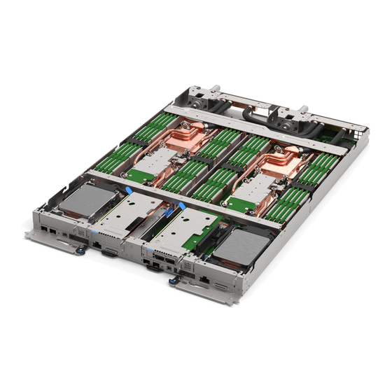
Page 9: Chapter 1. Thinksystem Sd650 V3, Types 7D7M
Chapter 1. ThinkSystem SD650 V3, Types 7D7M The ThinkSystem SD650 V3 is designed to deliver a dense, scalable platform for distributed enterprise and hyperconverged solutions. Note: The SD650 V3 tray contains two compute nodes. Figure 1. Enclosure with six SD650 V3 trays installed... - Page 10 Some of the features that are unique to the Lenovo XClarity Controller are enhanced performance, higher-resolution remote video, and expanded security options. The server supports Lenovo XClarity Controller 2 (XCC2). For additional information about Lenovo XClarity Controller 2 (XCC2), refer to https://sysmgt.lenovofiles.com/help/topic/lxcc_frontend/lxcc_overview.html...
-
Page 11: Tech Tips
5, and 10. Tech Tips Lenovo continually updates the support website with the latest tips and techniques that you can use to solve issues that your server might encounter. These Tech Tips (also called retain tips or service bulletins) provide procedures to work around issues or solve problems related to the operation of your server. -
Page 12: Technical Specifications
• New Socket Technology (Socket E with PCIe 5.0) LGA4677. Notes: 1. Use the Setup Utility to determine the type and speed of the processors in the node. 2. For a list of supported processors, see https://serverproven.lenovo.com ThinkSystem SD650 V3 Neptune DWC Tray User Guide... - Page 13 • Slots: – 16 DIMM slots per node, 8 DIMMs per processor. • Type: – Lenovo DDR5 at 4800 MT/s • Protection: – ECC – SDDC (for x4-based memory DIMMs) – ADDDC (for x4-based memory DIMMs) –...
- Page 14 “KVM breakout cable” on page • External LCD diagnostics handset connector • One Gigabit Ethernet port with RJ45 connector, shared between operating system and Lenovo XClarity Controller. • Two 25Gb SFP28 ports. One port is shared between operating system and Lenovo XClarity Controller.
- Page 15 Supported and certified operating systems: • Red Hat Enterprise Linux • SUSE Linux Enterprise Server References: • Complete list of available operating systems: https://lenovopress.lenovo.com/osig • OS deployment instructions, see “Deploy the operating system” on page 207. Chapter 1 ThinkSystem SD650 V3, Types 7D7M...
-
Page 16: Mechanical Specifications
• These levels were measured in controlled acoustical environments according to procedures specified by ISO 7779, and are reported in accordance with ISO 9296. • The declared acoustic noise levels are based on specified configurations (one enclosure with 6 PSUs), and may change depending on configuration/condition changes. ThinkSystem SD650 V3 Neptune DWC Tray User Guide... - Page 17 – Operating: ASHRAE Class A2: 8% - 80%, maximum dew point : 21°C (70°F) – Shipment/storage: 8% - 90% • Maximum altitude: 3048 m (10 000 ft) Note: The solution is designed for standard data center environment and recommended to be placed in industrial data center. Chapter 1 ThinkSystem SD650 V3, Types 7D7M...
-
Page 18: Particulate Contamination
Risks that are posed by the presence of excessive particulate levels or concentrations of harmful gases include damage that might cause the device to malfunction or cease functioning altogether. This specification sets forth limits for particulates and gases that are intended to avoid such damage. The limits ThinkSystem SD650 V3 Neptune DWC Tray User Guide... -
Page 19: Management Options
If Lenovo determines that the levels of particulates or gases in your environment have caused damage to the device, Lenovo may condition provision of repair or replacement of devices or parts on implementation of appropriate remedial measures to mitigate such environmental contamination. - Page 20 Suitable both for single-server or multi-server management contexts. Interface • OneCLI: CLI application Lenovo XClarity Essentials • Bootable Media Creator: CLI application, GUI application toolset • UpdateXpress: GUI application Usage and downloads http://sysmgt.lenovofiles.com/help/topic/xclarity_essentials/overview.html ThinkSystem SD650 V3 Neptune DWC Tray User Guide...
- Page 21 Important: Lenovo XClarity Provisioning Manager (LXPM) supported version varies by product. All versions of Lenovo XClarity Provisioning Manager are referred to as Lenovo XClarity Provisioning Manager and LXPM in this document, unless specified otherwise. To see the LXPM version supported by your server, go to https:// sysmgt.lenovofiles.com/help/topic/lxpm_frontend/lxpm_product_page.html...
- Page 22 √ √ density servers only) Notes: 1. Most options can be updated through the Lenovo tools. Some options, such as GPU firmware or Omni- Path firmware require the use of supplier tools. ThinkSystem SD650 V3 Neptune DWC Tray User Guide...
- Page 23 2. The server UEFI settings for option ROM must be set to Auto or UEFI to update firmware using Lenovo XClarity Administrator, Lenovo XClarity Essentials, or Lenovo XClarity Controller. 3. Firmware updates are limited to Lenovo XClarity Provisioning Manager, Lenovo XClarity Controller, and UEFI updates only.
- Page 24 ThinkSystem SD650 V3 Neptune DWC Tray User Guide...
-
Page 25: Chapter 2. Server Components
USB 3.0 (5 Gbps) / 2.0 connector. XCC mobile management is supported by USB 2.0 connector on the KVM breakout cable only. For more information, see “KVM breakout cable” on page © Copyright Lenovo 2022... -
Page 26: Top View
“Front LEDs” on page 211 for more information. NMI button. 25 Gb SFP28 Ethernet port with share-NIC feature for Lenovo Press this button to force a nonmaskable XClarity Controller. See “Front LEDs” on page 211 for more interrupt to the processor. You might have to information. -
Page 27: System-Board Layout (Compute Node)
Figure 4. Connectors and components on the KVM breakout cable Table 4. Connectors and components on the console breakout cable Serial port connector Retention buttons • Removal—Press the buttons; then, disconnect the KVM breakout cable from the server. • Installation—Press the buttons while connecting the KVM breakout cable to the server;... -
Page 28: System-Board Switches
The following illustration shows the location and description of the switches. Note: If there is a clear protective sticker on the top of the switch blocks, you must remove and discard it to access the switches. ThinkSystem SD650 V3 Neptune DWC Tray User Guide... -
Page 29: Pcie Slot Numbering
Figure 7. Switches on compute node system board Important: 1. Before you change any switch settings or move any jumpers, turn off the solution; then, disconnect all power cords and external cables. Review the following information: • http://thinksystem.lenovofiles.com/help/topic/safety_documentation/pdf_files.html • “Installation Guidelines” on page 33 •... -
Page 30: System Leds And Diagnostics Display
System LEDs and diagnostics display See the following section for information on available enclosure LEDs and diagnostics display. For more information, refer to “Troubleshooting by system LEDs and diagnostics display” on page 211. ThinkSystem SD650 V3 Neptune DWC Tray User Guide... -
Page 31: Chapter 3. Parts List
Tier 1 CRU at your request with no service agreement, you will be charged for the installation. • Tier 2 customer replaceable unit (CRU): You may install a Tier 2 CRU yourself or request Lenovo to install it, at no additional charge, under the type of warranty service that is designated for your solution. - Page 32 2. Click Parts. 3. Enter the serial number to view a listing of parts for your solution. Tray cover √ Rear cross brace √ Power distribution board √ Water loop √ DIMM comb √ ThinkSystem SD650 V3 Neptune DWC Tray User Guide...
-
Page 33: Power Cords
Table 9. SD650 V3 parts list (continued) Index Description Tier 1 CRU Tier 2 Consuma- ble and Structural part DIMM tool √ Memory module √ Memory module filler √ VR water clamp plate √ VR water loop trough √ System board √... - Page 34 The cord set should have the appropriate safety approvals for the country in which the equipment will be installed. • Power cords for a specific country or region are usually available only in that country or region. ThinkSystem SD650 V3 Neptune DWC Tray User Guide...
-
Page 35: Chapter 4. Unboxing And Setup
They might be required to receive warranty service. Identify the solution and access the Lenovo XClarity Controller This section contains instruction on how to identify your solution and where to find the Lenovo XClarity Controller access information. - Page 36 Lenovo XClarity Controller network access label In addition, the Lenovo XClarity Controller network access label for both nodes can be found on the pull out information tag located at the front of the tray. You can use the information on the pull out tag to access the XCC MAC address and LLA for each node.
- Page 37 Figure 12. Lenovo XClarity Controller network access label on the pull-out information tab Service Label and QR code In addition, the system Service Label is located on the inside surface of the tray cover, provides a quick response (QR) code for mobile access to service information. You can scan the QR code with a mobile device using a QR code reader application and get quick access to the Service Information web page.
-
Page 38: Solution Setup Checklist
Typically, you will need to connect the following cables: • Connect solution to the power source • Connect solution to the data network • Connect the solution to the storage device ThinkSystem SD650 V3 Neptune DWC Tray User Guide... - Page 39 • You can press the power button. • The solution can restart automatically after a power interruption. • The solution can respond to remote power-on requests sent to the Lenovo XClarity Controller. Note: You can access the management processor interface to configure the system without powering on the solution.
- Page 40 ThinkSystem SD650 V3 Neptune DWC Tray User Guide...
-
Page 41: Chapter 5. Hardware Replacement Procedures
• If you replace a part, such as an adapter, that contains firmware, you might also need to update the firmware for that part. For more information about updating firmware, See “Update the firmware” on page 201. © Copyright Lenovo 2022... -
Page 42: Safety Inspection Checklist
Note: The product is not suitable for use at visual display workplaces according to §2 of the Workplace Regulations. Note: The set-up of the server is made in the server room only. CAUTION: ThinkSystem SD650 V3 Neptune DWC Tray User Guide... -
Page 43: System Reliability Guidelines
Click Power ➙ Power Cables to see all line cords. • Make sure that the insulation is not frayed or worn. 3. Check for any obvious non-Lenovo alterations. Use good judgment as to the safety of any non-Lenovo alterations. -
Page 44: Handling Static-Sensitive Devices
The following memory configurations are available: • Independent memory mode • Memory mirroring Information about optimizing memory performance and configuring memory is available at the Lenovo Press website: https://lenovopress.lenovo.com/servers/options/memory In addition, you can take advantage of a memory configurator, which is available at the following site: https://dcsc.lenovo.com/#/memory_configuration... -
Page 45: Gap Pad/Putty Pad Identification And Location
Specific information about the required installation order of memory modules in your solution based on the system configuration and memory mode that you are implementing is shown below. DRAM DIMM installation order The tray only supports fully populated processor and memory configuration (2 processors and 16 DIMMs per node). - Page 46 Pad index Pad category Attached component Pad orientation Water loop Gap pad Gray side facing outward Gap pad Water loop Gray side facing outward Gap pad Water loop Gray side facing outward ThinkSystem SD650 V3 Neptune DWC Tray User Guide...
-
Page 47: Power On And Power Off The Solution
Table 12. Gap pads and putty pads used in SD650 V3 (continued) Pad index Pad category Attached component Pad orientation Gap pad Water loop Gray side facing outward Water loop Gap pad Gray side facing outward Gap pad Water loop Gray side facing outward Gap pad Water loop... -
Page 48: Power On The Solution
“Power off the solution” on page Power off the solution The solution remains in a standby state when it is connected to a power source, allowing the Lenovo XClarity Controller to respond to remote power-on requests. To remove all power from the solution (power status LED off), you must disconnect all power cables. - Page 49 • Disconnect all external cables from the enclosure. • Use extra force to disconnect QSFP cables if they are connected to the solution. • For your safety, use the lift tool to remove the tray from the rack. Note: The following illustration might differ slightly from your hardware, but the installation method is the same.
- Page 50 Rotate the front cam handles on the front of the DWC tray to the closed position to secure the tray in the enclosure. Note: Depending on the model, your solution might look slightly different from the illustration. ThinkSystem SD650 V3 Neptune DWC Tray User Guide...
-
Page 51: Tray Cover Replacement
Figure 16. Tray installation Tray bay filler Note: After the DWC tray is installed, the XCC in the DWC tray initializes. This process takes approximately 110 seconds. The power LED flashes rapidly, and the power button on the DWC tray does not respond until this process is complete. - Page 52 “Installation Guidelines” on page 33 “Safety inspection checklist” on page 34 to ensure that you work safely. Note: The following illustration might differ slightly from your hardware, but the installation method is the same. ThinkSystem SD650 V3 Neptune DWC Tray User Guide...
-
Page 53: Cross Braces Replacement
Watch the procedure A video of this procedure is available at YouTube: https://www.youtube.com/playlist?list=PLYV5R7hVcs- BQs0NXGCm6ZwVtMOSykxd Procedure Step 1. Position the cover on top of the tray and slide the cover towards the front of the tray. Figure 18. Tray cover installation Important: Before you slide the cover forward, make sure that all the tabs on the front, rear, and side of the cover are engaged with the enclosure correctly. - Page 54 “Remove a DWC tray from the enclosure” on page Remove the tray cover. See “Remove the tray cover” on page Step 2. Remove the front and the rear cross braces (14x Phillips #1 screws). ThinkSystem SD650 V3 Neptune DWC Tray User Guide...
- Page 55 Figure 19. Cross brace removal (SD650 V3) After you finish If you are instructed to return the component or optional device, follow all packaging instructions, and use any packaging materials for shipping that are supplied to you. Install the cross braces Use this information to install the cross braces.
-
Page 56: Water Loop Replacement
4. Check the power LED on each node to make sure it changes from fast blink to slow blink to indicate all nodes are ready to be powered on. Water loop replacement (trained technician only) Use the following procedures to remove and install the water loop in the SD650 V3 tray. ThinkSystem SD650 V3 Neptune DWC Tray User Guide... - Page 57 Attention: The water loop requires two trained personnels to complete the installation/removal task. Remove the water loop Use this information to remove the water loop in the SD650 V3 tray. About this task Attention: • Read “Installation Guidelines” on page 33 “Safety inspection checklist”...
- Page 58 • Ten Torx T10 screws on the rear of the node. Figure 22. Quick connect screw removal Step 4. Remove water loop screws (18x Torx T10 screws for two nodes) with a torque screwdriver set to the proper torque. ThinkSystem SD650 V3 Neptune DWC Tray User Guide...
- Page 59 Note: For reference, the torque required for the screws to be fully tightened/removed is 0.5-0.6 newton-meters, 4.5-5.5 inch-pounds. Figure 23. Water loop screw removal Step 5. Orient two water loop carriers with the guide pins; then, gently put the two water loop carriers down and ensure they are seated firmly on the water loop.
- Page 60 Figure 24. Water loop carrier installation Step 6. Tighten water loop carrier screws (24x Phillips #2 screws for two nodes). ThinkSystem SD650 V3 Neptune DWC Tray User Guide...
- Page 61 Figure 25. Water loop carrier screws installation Step 7. Loosen processors properly. Fully loosen all Torx T30 captive screws (16x Torx T30 captive screws for two nodes) on cold plates in the removal sequence shown on the cold plate label (with a torque screwdriver set to the proper torque).
- Page 62 Figure 26. Loosening Torx T30 captive screws Step 8. Carefully rotate the water loop so one half is sitting on top of the other half. ThinkSystem SD650 V3 Neptune DWC Tray User Guide...
- Page 63 Figure 27. Folding the water loop Step 9. Fasten two captive thumbscrews to secure water loop carriers to each other. Figure 28. Tightening captive thumbscrews Step 10. Remove the processor from the retainer. This process differs by processor SKU. Check the processor SKU and follow the applicable procedure.
- Page 64 Step 11. Without putting the processor down, wipe the thermal grease from the top of the processor with an alcohol cleaning pad; then, place the processor on a static protective surface with the processor- contact side up. Step 12. Remove the processor retainer from the underside of the cold plate. ThinkSystem SD650 V3 Neptune DWC Tray User Guide...
- Page 65 Note: The processor retainer will be discarded and replaced with a new one. Carefully release the retaining clips from the cold plate. Lift the retainer from the cold plate. Figure 31. Processor retainer removal Step 13. Wipe the thermal grease from the bottom of the cold plate with an alcohol cleaning pad. Step 14.
- Page 66 • To avoid damaging the water loop, always use the water loop carrier when removing, installing or folding the water loop. Note: Ensure you have “SD650 V3 Neptune DWC Waterloop Service Kit” in hand to install components. ThinkSystem SD650 V3 Neptune DWC Tray User Guide...
- Page 67 Important: Gap pad/putty pad replacement guidelines • To identify the gap pad/putty pad location and orientation, see “Gap pad/Putty pad identification and location” on page • Before replacing the gap pad/putty pad, gently clean the interface plate or the hardware surface with an alcohol cleaning pad.
- Page 68 When removing the water loop from the package box, make sure to hold the touch points marked in grey in the illustration below. Attention: Holding the water loop anywhere other than the touch points may cause damage to it. ThinkSystem SD650 V3 Neptune DWC Tray User Guide...
- Page 69 Isometric view of water loop Top image Top view of the water loop Bottom image Figure 35. Touching points when removing water loop from package box Step 4. Remove two plastic grease covers if needed. Use a pair of scissors to cut off the tape. Remove plastic grease covers from the underside of water loop cold plates.
- Page 70 Figure 37. Processor installation Step 6. Rotate all anti-tilt wire bails (8x anti-tilt wire bails per node) outwards to the unlocked position. ThinkSystem SD650 V3 Neptune DWC Tray User Guide...
- Page 71 Figure 38. Processor unlocked position Step 7. Check the gap pads on the water loop, if any of them are damaged or missing, replace them with the new ones. Figure 39. Water loop gap pads Make sure to follow Gap pad/putty pad replacement guidelines.
- Page 72 Step 10. Repeat step 6 to make sure gap pads are securely attached to water loop. Step 11. Fully loosen two captive thumbscrews located at each end of the water loop carrier. ThinkSystem SD650 V3 Neptune DWC Tray User Guide...
- Page 73 Figure 41. Loosening captive thumbscrews Step 12. Unfold and install the other side of the water loop as shown. Figure 42. Unfolding water loop Step 13. Ensure the processors are secured properly. Rotate anti-tilt wire bails (16x anti-tilt wire bails for two nodes) outwards to the locked position.
- Page 74 Attention: To prevent damage to components, make sure that you follow the indicated tightening sequence. Figure 43. Securing Torx T30 captive screws Step 14. Loosen water loop carrier screws (24x Phillips #2 screws for two nodes). ThinkSystem SD650 V3 Neptune DWC Tray User Guide...
- Page 75 Figure 44. Loosening water loop carrier screws Step 15. Carefully lift each water loop carrier up and away from the water loop one at a time. Chapter 5 Hardware replacement procedures...
- Page 76 Step 16. Install water loop screws (18x Torx T10 screws per node) with a torque screwdriver set to the proper torque. Note: For reference, the torque required for the screws to be fully tightened/removed is 0.5-0.6 newton-meters, 4.5-5.5 inch-pounds. ThinkSystem SD650 V3 Neptune DWC Tray User Guide...
- Page 77 Figure 46. Water loop screws installation Step 17. Install the following screws to secure the quick connect. • Four Torx T10 screws to secure the quick connect. • Ten Torx T10 screws on the rear of the node. Figure 47. Quick connect screw installation Step 18.
-
Page 78: Replace Components In The Compute Node
Replace components in the compute node Use the following information to remove and install compute node components. Notes: • The illustrations in this document are for reference only and might differ slightly from your hardware. ThinkSystem SD650 V3 Neptune DWC Tray User Guide... -
Page 79: Cmos Battery (Cr2032) Replacement
• S004 CAUTION: When replacing the lithium battery, use only Lenovo specified part number or an equivalent type battery recommended by the manufacturer. If your system has a module containing a lithium battery, replace it only with the same module type made by the same manufacturer. The battery contains lithium and can explode if not properly used, handled, or disposed of. - Page 80 – Lenovo has designed this product with your safety in mind. The lithium battery must be handled correctly to avoid possible danger. If you replace the battery, you must adhere to the following instructions. – If you replace the original lithium battery with a heavy-metal battery or a battery with heavy-metal components, be aware of the following environmental consideration.
- Page 81 • S004 CAUTION: When replacing the lithium battery, use only Lenovo specified part number or an equivalent type battery recommended by the manufacturer. If your system has a module containing a lithium battery, replace it only with the same module type made by the same manufacturer. The battery contains lithium and can explode if not properly used, handled, or disposed of.
- Page 82 As you slide the CMOS battery into place, press the top of the CMOS battery into the socket. Make sure that the battery clip holds the battery securely. ThinkSystem SD650 V3 Neptune DWC Tray User Guide...
-
Page 83: Dimm Comb Replacement
Figure 52. CMOS battery installation After you finish 1. Install the PCIe riser assembly. See “Install a PCIe riser assembly (ConnectX-6)” on page 123 “PCIe riser assembly replacement (ConnectX-7 NDR 200)” on page 128, or “Install a PCIe riser assembly (ConnectX-7 NDR 400)”... - Page 84 Note: Memory module tool is recommended due to space limitations caused by location of water loop tubes through the memory section. Step 3. Gently hold the DIMM comb and removal it out of the chassis. ThinkSystem SD650 V3 Neptune DWC Tray User Guide...
- Page 85 Figure 54. DIMM comb removal After you finish If you are instructed to return the component or optional device, follow all packaging instructions, and use any packaging materials for shipping that are supplied to you. Install a DIMM comb Use this information to install a DIMM comb. About this task Attention: •...
- Page 86 After you finish 1. Install the tray cover. See “Install the tray cover” on page 2. Install the tray into the enclosure. See “Install a DWC tray in the enclosure” on page ThinkSystem SD650 V3 Neptune DWC Tray User Guide...
-
Page 87: Drive Replacement
3. Connect all required external cables to the solution. Note: Use extra force to connect QSFP cables to the solution. 4. Check the power LED on each node to make sure it changes from fast blink to slow blink to indicate all nodes are ready to be powered on. - Page 88 Push and hold the release latch. Slide the metal tab to the unlocked position. Pivot the drive out of the top of the drive cage as shown. Disconnect the cable from the drive. ThinkSystem SD650 V3 Neptune DWC Tray User Guide...
- Page 89 Figure 59. Upper drive removal 2. Remove the lower drive. Remove the drive out of the bottom of the drive cage. Disconnect the cable from the drive. Figure 60. Lower drive removal 3. If necessary, remove the four screws securing the conduction plate and lift it out of the drive cage.
- Page 90 • The putty pad is unfit for use if the expiry date on its packaging has passed. Acquire a new putty pad for proper putty pad replacement procedure. ThinkSystem SD650 V3 Neptune DWC Tray User Guide...
- Page 91 Watch the procedure A video of this procedure is available at YouTube: https://www.youtube.com/playlist?list=PLYV5R7hVcs- BQs0NXGCm6ZwVtMOSykxd Procedure Step 1. For installing one 7 mm or 15 mm drive only, complete the following steps. Find the cable with its plugger marked as SSD 0/2, and connect it to the drive. Flip the drive over.
- Page 92 Note: Make sure the metal tab is in the unlocked position. Figure 64. Conduction plate installation 2. Install the lower drive. Find the cable with its plugger marked as SSD 0/2, and connect it to the drive. Flip the drive over. ThinkSystem SD650 V3 Neptune DWC Tray User Guide...
- Page 93 Install the drive into the bottom of the drive cage and make sure it is secured in place. Figure 65. Lower drive installation 3. Install the upper drive. Find the cable with its plugger marked as SSD 1/3, and connect it to the drive. Then, pivot the drive into the top of the drive cage as shown.
-
Page 94: Drive Cage Assembly Replacement
Remove the cross braces. See “Remove the cross braces” on page Step 2. Disconnect the cables from the system board. Figure 67. Drive assembly cable routing SATA 0-1 connector NVMe 0-1 connector ThinkSystem SD650 V3 Neptune DWC Tray User Guide... - Page 95 Drive power 2 connector SATA 2-3 connector NVMe 2-3 connector Drive power 1 connector Step 3. Remove the drive cage assembly. Remove the 3 screws. Remove the drive assembly out of the node. Figure 68. One 15 mm drive cage assembly removal Chapter 5 Hardware replacement procedures...
- Page 96 Figure 69. One 7 mm drive cage assembly removal Figure 70. Two 7 mm drive cage assembly removal Step 4. If necessary, install the blank bezel fillers. ThinkSystem SD650 V3 Neptune DWC Tray User Guide...
- Page 97 Figure 71. Blank bezel filler installation If you are instructed to return the component or optional device, follow all packaging instructions, and use any packaging materials for shipping that are supplied to you. Install a drive cage assembly Use this information to install a drive cage assembly. About this task Attention: •...
- Page 98 If the drive cage gap pad is damaged or missing, replace it with a new one. See the following for the gap pad location for each drive cage. Make sure to follow Gap pad/putty pad replacement guidelines. ThinkSystem SD650 V3 Neptune DWC Tray User Guide...
- Page 99 Figure 74. Replacing gap pad Figure 75. Gap pad locations Step 4. Install the drive cage assembly. Install the drive assembly into the node. Secure the 3 screws. Chapter 5 Hardware replacement procedures...
- Page 100 Figure 76. One 15 mm drive cage assembly installation Figure 77. One 7 mm drive cage assembly installation ThinkSystem SD650 V3 Neptune DWC Tray User Guide...
- Page 101 Figure 78. Two 7 mm drive cage assembly installation Step 5. Connect the drive assembly cable to the system board and route the cable as the following illustration. Figure 79. Drive assembly cable routing SATA 0-1 connector NVMe 0-1 connector Drive power 2 connector SATA 2-3 connector Chapter 5...
-
Page 102: Kvm Cover Replacement
“Remove the tray cover” on page Step 2. Disconnect the KVM cable from the tray. Step 3. Remove the screws that secure the KVM cover to the tray; then, remove the KVM cover. ThinkSystem SD650 V3 Neptune DWC Tray User Guide... - Page 103 Figure 80. Removing the KVM cover If you are instructed to return the component or optional device, follow all packaging instructions, and use any packaging materials for shipping that are supplied to you. Install a KVM cover Use this information to install a KVM cover. About this task Attention: •...
-
Page 104: M.2 Backplane Assembly Replacement
• Disconnect all external cables from the enclosure. • Use extra force to disconnect QSFP cables if they are connected to the solution. Watch the procedure A video of this procedure is available at YouTube: https://www.youtube.com/playlist?list=PLYV5R7hVcs- BQs0NXGCm6ZwVtMOSykxd Procedure ThinkSystem SD650 V3 Neptune DWC Tray User Guide... - Page 105 Step 1. Make preparations for this task. Remove the tray from the enclosure. See “Remove a DWC tray from the enclosure” on page Remove the tray cover. See “Remove the tray cover” on page Remove the cross braces. See “Remove the cross braces” on page Step 2.
- Page 106 Figure 83. M.2 backplane assembly removal Step 4. (Optional) If you are removing the water loop, remove the M.2 backplane cold plate. Unfasten the two screws. Remove the M.2 backplane cold plate from the processor cold plate. ThinkSystem SD650 V3 Neptune DWC Tray User Guide...
- Page 107 Figure 84. Removing the M.2 backplane cold plate removal After you finish If you are instructed to return the component or optional device, follow all packaging instructions, and use any packaging materials for shipping that are supplied to you. If you need to disassemble the M.2 backplane assembly for recycle, follow the instructions below: Attention: You can only disassemble the M.2 backplane assembly for recycle.
- Page 108 • Go to “Update the firmware” on page 201 for more information on firmware updating tools. Watch the procedure A video of this procedure is available at YouTube: https://www.youtube.com/playlist?list=PLYV5R7hVcs- BQs0NXGCm6ZwVtMOSykxd ThinkSystem SD650 V3 Neptune DWC Tray User Guide...
- Page 109 Procedure Step 1. Replace the putty pad on the processor (Processor 1) cold plate with a new one. Make sure to follow Gap pad/putty pad replacement guidelines. Figure 86. Gap pad on processor cold plate Step 2. Install the M.2 backplane cold plate. Place the M.2 cold plate onto the front processor (Processor 1) cold plate.
- Page 110 Step 4. Install the M.2 backplane assembly. Connect the cable to the M.2 backplane assembly. Install the M.2 backplane assembly into the node. Secure the six screws. Figure 88. M.2 backplane assembly installation ThinkSystem SD650 V3 Neptune DWC Tray User Guide...
-
Page 111: M.2 Drive Replacement
Step 5. Connect the cable to the system board. Figure 89. M.2 backplane assembly cable installation After you finish 1. Install the cross braces. See “Install the cross braces” on page 2. Install the tray cover. See “Install the tray cover” on page 3. - Page 112 If you are instructed to return the component or optional device, follow all packaging instructions, and use any packaging materials for shipping that are supplied to you. Install an M.2 drive Use this information to install an M.2 drive. ThinkSystem SD650 V3 Neptune DWC Tray User Guide...
- Page 113 About this task Attention: • Read “Installation Guidelines” on page 33 “Safety inspection checklist” on page 34 to ensure that you work safely. Note: You may need the Gap Pad Kit to perform this task. Important: Gap pad/putty pad replacement guidelines •...
-
Page 114: Memory Module Replacement
Remove a memory module Use this information to remove a memory module. About this task Attention: • Read “Installation Guidelines” on page 33 “Safety inspection checklist” on page 34 to ensure that you work safely. ThinkSystem SD650 V3 Neptune DWC Tray User Guide... - Page 115 • Turn off the corresponding DWC tray that you are going to perform the task on. • Disconnect all external cables from the enclosure. • Use extra force to disconnect QSFP cables if they are connected to the solution. • Memory modules are sensitive to static discharge and require special handling. In addition to the standard guidelines for “Handling static-sensitive devices”...
- Page 116 Note: Memory module tool is recommended due to space limitations caused by location of water loop tubes through the memory section. Step 3. Carefully use the memory module tool to press the retaining clips outward on each end of the memory module connector. ThinkSystem SD650 V3 Neptune DWC Tray User Guide...
- Page 117 Figure 95. Pressing retaining clips on memory module connector Attention: • Memory modules are static-sensitive devices. The package must be grounded before it is opened. • To avoid breaking the retaining clips or damaging the memory module connectors, open and close the clips gently.
- Page 118 Figure 97. Memory module tool installation After you finish If you are instructed to return the component or optional device, follow all packaging instructions, and use any packaging materials for shipping that are supplied to you. ThinkSystem SD650 V3 Neptune DWC Tray User Guide...
- Page 119 Install a memory module Use this information to install a memory module. About this task “Memory module installation rules and order” on page 36 for detailed information about memory configuration and setup. Attention: • Read “Installation Guidelines” on page 33 “Safety inspection checklist”...
- Page 120 Note: Memory module tool is recommended due to space limitations caused by location of water loop tubes through the memory section. Step 2. Carefully use the memory module tool to press the retaining clips outward on each end of the memory module connector. ThinkSystem SD650 V3 Neptune DWC Tray User Guide...
- Page 121 Figure 100. Pressing retaining clips on memory module connector Attention: • Memory modules are static-sensitive devices. The package must be grounded before it is opened. • To avoid breaking the retaining clips or damaging the memory module connectors, open and close the clips gently.
- Page 122 Step 6. Install the memory module tool to the DIMM comb. Figure 102. Memory module tool installation ThinkSystem SD650 V3 Neptune DWC Tray User Guide...
-
Page 123: Pcie Adapter Replacement
After you finish 1. Install the tray cover. See “Install the tray cover” on page 2. Install the tray into the enclosure. See “Install a DWC tray in the enclosure” on page 3. Connect all required external cables to the solution. Note: Use extra force to connect QSFP cables to the solution. - Page 124 Gently grasp and pull the black plastic sheets outward. Pull the cable connectors out of the adapter. Figure 104. PCIe adapter cable removal Step 4. If necessary, install a filler into the PCIe riser-cage and secure it with a screw. ThinkSystem SD650 V3 Neptune DWC Tray User Guide...
- Page 125 Figure 105. Filler installation After you finish If you are instructed to return the component or optional device, follow all packaging instructions, and use any packaging materials for shipping that are supplied to you. Install a PCIe adapter Use this information to install a PCIe adapter. About this task Attention: •...
- Page 126 • There are WHITE CABLE and BLACK CABLE callouts on the adapter, connect the cables to the connectors according to the cable colors. • There are MAIN and AUX labels on cables, connect MAIN ends to the main adapter and connect AUX ends to the auxiliary adapter. ThinkSystem SD650 V3 Neptune DWC Tray User Guide...
-
Page 127: Pcie Riser Assembly Replacement (Connectx-6)
Step 3. Align the adapter with the PCIe slot on the riser-cage; then, carefully press the adapter straight into the slot until it is securely seated. Fasten the screw to secure the adapter. Figure 108. PCIe adapter installation After you finish 1. - Page 128 Loosen the PCIe riser assembly. Loosen the captive screw on the PCIe riser assembly. Loosen the captive screw on the clamp bracket and remove it. Remove the screw that secures the riser assembly. ThinkSystem SD650 V3 Neptune DWC Tray User Guide...
- Page 129 Figure 110. Clamp bracket captive screw removal Step 4. Carefully grasp the PCIe riser-cage assembly by its edges and remove it out of the node. Figure 111. PCIe riser assembly removal Chapter 5 Hardware replacement procedures...
- Page 130 If you are instructed to return the component or optional device, follow all packaging instructions, and use any packaging materials for shipping that are supplied to you. If you need to disassemble the PCIe riser assembly, follow the instructions below: ThinkSystem SD650 V3 Neptune DWC Tray User Guide...
- Page 131 Attention: You can only disassemble a PCIe riser assembly for recycle. Do not disassemble it for any other purposes. 1. Remove the two screws, then, separate the expansion board from the cage. Figure 114. Expansion board removal 2. Recycle the unit in compliance with local regulations. Install a PCIe riser assembly (ConnectX-6) Use this information to install a PCIe riser assembly with ConnectX-6 adapter.
- Page 132 Torx T10 screws. Figure 116. Interface plate installation Step 3. Replace the interface plate putty pad with a new one. Make sure to follow Gap pad/putty pad replacement guidelines. ThinkSystem SD650 V3 Neptune DWC Tray User Guide...
- Page 133 Figure 117. Interface plate putty pad for CX-6 riser Step 4. Install the PCIe riser assembly. Install one hex standoff screw to the cold plate. Align the tab on the PCIe riser assembly with the slot on the front of the node; then, insert the PCIe riser assembly onto the system board.
- Page 134 Figure 118. PCIe riser assembly installation Step 5. Secure the PCIe riser assembly. Install the clamp bracket and fasten the captive screw. Fasten the captive screw on the PCIe riser assembly. ThinkSystem SD650 V3 Neptune DWC Tray User Guide...
- Page 135 Figure 119. Clamp bracket captive screw installation Step 6. If necessary, install the heatpipe beam and secure it with one screw. Figure 120. Heatpipe beam installation After you finish 1. For shared I/O or socket direct configurations, route the cables. See Chapter 6 “Internal cable routing”...
-
Page 136: Pcie Riser Assembly Replacement
Loosen the screw on the front of the PCIe riser assembly Loosen the captive screw on the rear of the PCIe riser assembly. Remove the two long screws that secure the riser assembly. ThinkSystem SD650 V3 Neptune DWC Tray User Guide... - Page 137 Figure 121. Clamp bracket captive screw removal Step 3. Carefully grasp the PCIe riser-cage assembly by its edges and remove it out of the node. Note: The following illustration might differ slightly from your hardware, but the removal method is the same.
- Page 138 Figure 122. PCIe riser assembly removal Step 4. If necessary, remove the interface plate. Remove the hex standoff screw and five Torx T10 screws that secure the interface plate. ThinkSystem SD650 V3 Neptune DWC Tray User Guide...
- Page 139 Figure 123. Interface plate removal Release the interface plate with a flat head screwdriver. (If a flat head screwdriver is not available, the DIMM tool can also be used.) 1. There are two openings (marked with black triangle in the illustration below) on the bottom side of the interface plate for inserting a flat head screwdriver—select the one that is accessible for the flat head screwdriver.
- Page 140 Figure 124. Locations of openings on the bottom side of the interface plate Figure 125. Releasing the interface plate from water loop cold plate Remove the interface plate from the tray. ThinkSystem SD650 V3 Neptune DWC Tray User Guide...
- Page 141 Figure 126. Removing the interface plate Step 5. If necessary, install the blank bezel fillers. Figure 127. Blank bezel filler installation After you finish If you are instructed to return the component or optional device, follow all packaging instructions, and use any packaging materials for shipping that are supplied to you.
- Page 142 • The putty pad is unfit for use if the expiry date on its packaging has passed. Acquire a new putty pad for proper putty pad replacement procedure. Watch the procedure A video of this procedure is available at YouTube: https://www.youtube.com/playlist?list=PLYV5R7hVcs- BQs0NXGCm6ZwVtMOSykxd Procedure Step 1. Remove the blank bezel fillers if they are installed. ThinkSystem SD650 V3 Neptune DWC Tray User Guide...
- Page 143 Figure 129. Blank bezel filler removal Step 2. If the interface plate was removed, place the interface plate onto the node; then, secure the interface plate with five Phillips #2 screws. Figure 130. Interface plate installation Step 3. Replace the interface plate putty pad with a new one. Make sure to follow Gap pad/putty pad replacement guidelines.
- Page 144 Align the tab on the PCIe riser assembly with the slot on the front of the node; then, insert the PCIe riser assembly onto the system board. Secure the riser assembly with one screw. ThinkSystem SD650 V3 Neptune DWC Tray User Guide...
- Page 145 Figure 132. PCIe riser assembly installation Step 5. Secure the PCIe riser assembly. Install the clamp bracket and fasten the captive screw. Fasten the captive screw on the PCIe riser assembly. Install two screws to secure the PCIe riser assembly. Chapter 5 Hardware replacement procedures...
-
Page 146: Pcie Riser Assembly Replacement
“Installation Guidelines” on page 33 “Safety inspection checklist” on page 34 to ensure that you work safely. • Turn off the corresponding DWC tray that you are going to perform the task on. ThinkSystem SD650 V3 Neptune DWC Tray User Guide... - Page 147 • Disconnect all external cables from the enclosure. • Use extra force to disconnect QSFP cables if they are connected to the solution. Watch the procedure A video of this procedure is available at YouTube: https://www.youtube.com/playlist?list=PLYV5R7hVcs- BQs0NXGCm6ZwVtMOSykxd Procedure Step 1. Make preparations for this task.
- Page 148 Carefully grasp the PCIe riser-cage assembly by its edges and remove it out of the node. Figure 136. Removing the PCIe riser cage assembly Step 3. If necessary, remove the interface plate. Remove the two Phillips #2 screws that secure the interface plate. ThinkSystem SD650 V3 Neptune DWC Tray User Guide...
- Page 149 Figure 137. Interface plate removal Release the interface plate with a flat head screwdriver. (If a flat head screwdriver is not available, the DIMM tool can also be used.) 1. There are two openings (marked with black triangle in the illustration below) on the bottom side of the interface plate for inserting a flat head screwdriver—select the one that is accessible for the flat head screwdriver.
- Page 150 Figure 138. Locations of openings on the bottom side of the interface plate Figure 139. Releasing the interface plate from water loop cold plate Remove the interface plate from the tray. ThinkSystem SD650 V3 Neptune DWC Tray User Guide...
- Page 151 Figure 140. Removing the interface plate Step 4. If necessary, install the blank bezel fillers. Figure 141. Blank bezel filler installation After you finish If you are instructed to return the component or optional device, follow all packaging instructions, and use any packaging materials for shipping that are supplied to you.
- Page 152 • The putty pad is unfit for use if the expiry date on its packaging has passed. Acquire a new putty pad for proper putty pad replacement procedure. Watch the procedure A video of this procedure is available at YouTube: https://www.youtube.com/playlist?list=PLYV5R7hVcs- BQs0NXGCm6ZwVtMOSykxd Procedure Step 1. Remove the blank bezel fillers if they are installed. ThinkSystem SD650 V3 Neptune DWC Tray User Guide...
- Page 153 Figure 143. Blank bezel filler removal Step 2. If the interface plate was removed, place the interface plate onto the node; then, secure the interface plate with two Phillips #2 screws. Figure 144. Interface plate installation Step 3. Replace the interface plate putty pad with a new one. Make sure to follow Gap pad/putty pad replacement guidelines.
- Page 154 Align the tab on the PCIe riser assembly with the slot on the front of the node; then, insert the PCIe riser assembly onto the system board. Secure the riser assembly with three screws. Fasten the captive screw on the PCIe riser assembly. ThinkSystem SD650 V3 Neptune DWC Tray User Guide...
-
Page 155: Power Distribution Board Replacement (Trained Technician Only)
Figure 146. PCIe riser assembly installation After you finish 1. For shared I/O or socket direct configurations, route the cables. See Chapter 6 “Internal cable routing” on page 195 for cable routing details. 2. Install the tray cover. See “Install the tray cover” on page 3. - Page 156 Remove the cross braces. See “Remove the cross braces” on page Step 2. Remove two Torx T10 screws (per node); then, remove the VR (voltage regulator) clamp plate out of the node. ThinkSystem SD650 V3 Neptune DWC Tray User Guide...
- Page 157 Figure 147. VR clamp plate removal Step 3. Remove water loop screws (9x Torx T10 screws per node) with a torque screwdriver set to the proper torque. Note: For reference, the torque required for the screws to be fully tightened/removed is 0.5-0.6 newton-meters, 4.5-5.5 inch-pounds.
- Page 158 Figure 149. Quick connect screw removal Step 5. Orient the water loop carrier with the guide pin; then, gently put the water loop carrier down and ensure it is seated firmly on the water loop. ThinkSystem SD650 V3 Neptune DWC Tray User Guide...
- Page 159 Figure 150. Water loop carrier installation Step 6. Tighten water loop carrier screws (12x Phillips #2 screws per node). Figure 151. Water loop carrier screws installation Chapter 5 Hardware replacement procedures...
- Page 160 Rotate all anti-tilt wire bails (8x anti-tilt wire bails per node) inwards to the unlocked position. Figure 152. Loosening processors Step 8. Carefully rotate the water loop so one half is sitting on top of the other half. ThinkSystem SD650 V3 Neptune DWC Tray User Guide...
- Page 161 Figure 153. Folding the water loop Step 9. Remove the power distribution board. Remove the five Phillips #1 screws (per node). Gently pull the power distribution board connector to disconnect it from the system board. Carefully pull the power distribution board inwards to disengage it from the node. Note: Use a 3/16"...
- Page 162 Tilt the power distribution board and align it with the hole; then, slide it into place. Gently push the power distribution board connector to ensure it is connected to the system board. Fasten the five Phillips #1 screws. ThinkSystem SD650 V3 Neptune DWC Tray User Guide...
- Page 163 Note: Use a 3/16" hex head screwdriver to ensure the proper removal and installation. Figure 155. Power distribution board installation Step 2. Check the gap pads on the water loop, if any of them are damaged or missing, replace them with the new ones.
- Page 164 Note: For reference, the torque required for the screws to be fully tightened/removed is 0.9-1.3 newton-meters, 8-12 inch-pounds. Attention: To prevent damage to components, make sure that you follow the indicated tightening sequence. ThinkSystem SD650 V3 Neptune DWC Tray User Guide...
- Page 165 Figure 158. Processors installation Step 5. Loosen water loop carrier screws (12x Phillips #2 screws per node). Figure 159. Loosening water loop carrier screws Step 6. Carefully lift the water loop carrier up and away from the water loop. Chapter 5 Hardware replacement procedures...
- Page 166 Install water loop screws (9x Torx T10 screws per node) with a torque screwdriver set to the proper torque. Note: For reference, the torque required for the screws to be fully tightened/removed is 0.5-0.6 newton-meters, 4.5-5.5 inch-pounds. ThinkSystem SD650 V3 Neptune DWC Tray User Guide...
- Page 167 Figure 161. Water loop screws installation Step 8. Install the following screws to secure the quick connect. • Two Torx T10 screws (per node) on the quick connect. • Five Torx T10 screws (per node) on the rear of the node. Figure 162.
- Page 168 Note: Use extra force to connect QSFP cables to the solution. 5. Check the power LED on each node to make sure it changes from fast blink to slow blink to indicate all nodes are ready to be powered on. ThinkSystem SD650 V3 Neptune DWC Tray User Guide...
-
Page 169: Processor Replacement (Trained Technician Only)
Processor replacement (trained technician only) Use the following procedures to replace an assembled processor. Attention: Before you begin replacing a processor, make sure that you use Lenovo proven alcohol cleaning pad and thermal grease. Important: The processor in your solution can throttle in response to thermal conditions, temporarily lowering its speed to reduce heat output. - Page 170 “Remove a PCIe riser assembly (ConnectX-7 NDR 400)” on page 138. Step 2. Remove two Torx T10 screws (per node); then, remove the VR (voltage regulator) clamp plate out of the node. ThinkSystem SD650 V3 Neptune DWC Tray User Guide...
- Page 171 Figure 165. VR clamp plate removal Step 3. Remove water loop screws (9x Torx T10 screws per node) with a torque screwdriver set to the proper torque. Note: For reference, the torque required for the screws to be fully tightened/removed is 0.5-0.6 newton-meters, 4.5-5.5 inch-pounds.
- Page 172 Figure 167. Quick connect screw removal Step 5. Orient the water loop carrier with the guide pin; then, gently put the water loop carrier down and ensure it is seated firmly on the water loop. ThinkSystem SD650 V3 Neptune DWC Tray User Guide...
- Page 173 Figure 168. Water loop carrier installation Step 6. Tighten water loop carrier screws (12x Phillips #2 screws per node). Figure 169. Water loop carrier screws installation Chapter 5 Hardware replacement procedures...
- Page 174 Rotate all anti-tilt wire bails (8x anti-tilt wire bails per node) inwards to the unlocked position. Figure 170. Loosening processors Step 8. Carefully rotate the water loop so one half is sitting on top of the other half. ThinkSystem SD650 V3 Neptune DWC Tray User Guide...
- Page 175 Figure 171. Folding the water loop Step 9. Remove the processor from the retainer. This process differs by processor SKU. Check the processor SKU and follow the applicable procedure. Note: Do not touch the contacts on the processor. For non Intel ®...
- Page 176 Step 11. Remove the processor retainer from the underside of the cold plate. Note: The processor retainer will be discarded and replaced with a new one. Carefully release the retaining clips from the cold plate. Lift the retainer from the cold plate. ThinkSystem SD650 V3 Neptune DWC Tray User Guide...
- Page 177 Figure 174. Processor retainer removal Step 12. Wipe the thermal grease from the bottom of the cold plate with an alcohol cleaning pad. After you finish If you are instructed to return the component or optional device, follow all packaging instructions, and use any packaging materials for shipping that are supplied to you.
- Page 178 Screwdriver Type Screw Type Torx T10 head screwdriver Torx T10 screw Torx T30 head screwdriver Torx T30 screw Phillips #1 head screwdriver Phillips #1 screw Phillips #2 head screwdriver Phillips #2 screw ThinkSystem SD650 V3 Neptune DWC Tray User Guide...
- Page 179 Figure 175. Processor locations Firmware and driver download: You might need to update the firmware or driver after replacing a component. • Go to https://datacentersupport.lenovo.com/products/servers/thinksystem/sd650v3/7d7m/downloads/driver- to see the latest firmware and driver updates for your server. list/ • Go to “Update the firmware”...
- Page 180 Figure 177. Installing a processor retainer Step 3. Remove two plastic grease covers if needed. Use a pair of scissors to cut off the tape. Remove plastic grease covers from the underside of water loop cold plates. ThinkSystem SD650 V3 Neptune DWC Tray User Guide...
- Page 181 Note: The right node is shown as example. Remove plastic grease covers if needed when installing processor in either node. Figure 178. Plastic grease covers removal Step 4. Align the triangular marks on the processor retainers with the triangular slots on the underside of the water loop cold plate;...
- Page 182 Carefully rotate the top side of the water loop, position the water loop on the two guide pins near the rear of the node; then, gently put the water loop down and ensure it is firmly seated on the system board. ThinkSystem SD650 V3 Neptune DWC Tray User Guide...
- Page 183 Figure 182. Water loop installation Step 8. Ensure the processors are secured properly. Rotate the anti-tilt wire bails (8x anti-tilt wire bails per node) outwards to the locked position. Fully tighten all Torx T30 captive screws (8x Torx T30 captive screws per node) on cold plates in the installation sequence shown on the cold plate label (with a torque screwdriver set to the proper torque).
- Page 184 Loosen water loop carrier screws (12x Phillips #2 screws per node). Figure 184. Loosening water loop carrier screws Step 10. Carefully lift the water loop carrier up and away from the water loop. ThinkSystem SD650 V3 Neptune DWC Tray User Guide...
- Page 185 Figure 185. Water loop carrier removal Step 11. Install water loop screws (9x Torx T10 screws per node) with a torque screwdriver set to the proper torque. Note: For reference, the torque required for the screws to be fully tightened/removed is 0.5-0.6 newton-meters, 4.5-5.5 inch-pounds.
- Page 186 • Five Torx T10 screws (per node) on the rear of the node. Figure 187. Quick connect screw installation Step 13. Install the VR clamp plate into the node and install Torx T10 screws (2x Torx T10 screw per nods). ThinkSystem SD650 V3 Neptune DWC Tray User Guide...
-
Page 187: System Board Replacement
Figure 188. VR clamp plate installation After you finish 1. Install the memory modules. See “Install a memory module” on page 111. 2. Install the DIMM comb. See “Install a DIMM comb” on page 3. Install the M.2 backplane assembly. See “Install the M.2 backplane assembly”... - Page 188 Remove the PCIe riser assembly. Depending on your configuration, see “Remove a PCIe riser assembly (ConnectX-6)” on page 119, “PCIe riser assembly replacement (ConnectX-7 NDR 200)” on page 128, or “Remove a PCIe riser assembly (ConnectX-7 NDR 400)” on page 138. ThinkSystem SD650 V3 Neptune DWC Tray User Guide...
- Page 189 Remove the power distribution board, and carefully rotate the water loop so one half is sitting on top of the other half. See “Remove the power distribution board” on page 148. Step 2. Remove the two Torx T10 screws (per node) to remove the VR water loop trough out of the system board.
- Page 190 If you need to disassemble the system board, follow the instructions below: Attention: You can only disassemble the system board for recycle. Do not disassemble it for any other purposes. 1. Remove the guide pin out of the system board. ThinkSystem SD650 V3 Neptune DWC Tray User Guide...
- Page 191 Figure 192. Guide pin removal 2. Recycle the unit in compliance with local regulations. Install the system board Use this information to install the system board. About this task Attention: • Read “Installation Guidelines” on page 33 “Safety inspection checklist” on page 34 to ensure that you work safely.
- Page 192 Orient the system board on the two guide pins near the rear of the node to insure proper alignment; then, carefully insert the system board into the node. Note: Avoid touching the connectors on the system board. Be careful not to damage any surrounding components inside the node. ThinkSystem SD650 V3 Neptune DWC Tray User Guide...
- Page 193 Figure 193. System board installation Step 2. Install and tighten seven Phillips #1 screws per node on the system board (with a torque screwdriver set to the proper torque). Figure 194. System board screws installation Note: For reference, the torque required for the screws to be fully tightened/removed is 0.5-0.6 newton-meters, 4.5-5.5 inch-pounds.
- Page 194 Step 4. Align the VR water loop trough with the holes on the system board; then, fasten the two Torx T10 screws (per node). Figure 196. VR water loop trough installation ThinkSystem SD650 V3 Neptune DWC Tray User Guide...
- Page 195 Using Lenovo XClarity Provisioning Manager Steps: 1. Start the server and press the key according to the on-screen instructions. The Lenovo XClarity Provisioning Manager interface is displayed by default. 2. Choose System Summary. The “System Summary” tab page is displayed.
- Page 196 Note: For customers in Chinese Mainland, integrated TPM is not supported. However, customers in Chinese Mainland can install a Trusted Cryptographic Module (TCM) adapter or a TPM adapter (sometimes called a daughter card). ThinkSystem SD650 V3 Neptune DWC Tray User Guide...
- Page 197 Note: Although the setting undefined is available as a policy setting, it should not be used. • From Lenovo XClarity Essentials OneCLI Note: Please note that a Local IPMI user and password must be setup in Lenovo XClarity Controller for remote accessing to the target system.
- Page 198 Lenovo XClarity Essentials OneCLI. To disable TPM, do the following: 1. Download and install Lenovo XClarity Essentials OneCLI. To download Lenovo XClarity Essentials OneCLI, go to the following site: https://datacentersupport.lenovo.com/solutions/HT116433 2. Run the following command: ThinkSystem SD650 V3 Neptune DWC Tray User Guide...
- Page 199 Follow the procedure below to see the TPM firmware version: From Lenovo XClarity Provisioning Manager 1. Start the server and press the key specified in the on-screen instructions to display the Lenovo XClarity Provisioning Manager interface. (For more information, see the “Startup” section in the LXPM documentation compatible with your server at https://sysmgt.lenovofiles.com/help/topic/lxpm_frontend/...
- Page 200 To enable UEFI Secure Boot from Lenovo XClarity Provisioning Manager: 1. Start the server and press the key specified in the on-screen instructions to display the Lenovo XClarity Provisioning Manager interface. (For more information, see the “Startup” section in the LXPM documentation compatible with your server at https://sysmgt.lenovofiles.com/help/topic/lxpm_frontend/...
-
Page 201: Complete The Parts Replacement
– <userid>:<password> are the credentials used to access the BMC (Lenovo XClarity Controller interface) of your server. The default user ID is USERID, and the default password is PASSW0RD (zero, not an uppercase o) – <ip_address> is the IP address of the BMC. - Page 202 ThinkSystem SD650 V3 Neptune DWC Tray User Guide...
-
Page 203: Chapter 6. Internal Cable Routing
“Socket direct configuration for ConnectX-7 NDR 200/ConnectX-7 NDR 400” on page 196 Shared I/O configuration for ConnectX-6 This configuration supports ConnectX-6. Figure 197. Shared I/O configuration for ConnectX-6 cable routing Main adapter with riser Auxiliary adapter with riser 350 mm IPEX cable (CX-6) © Copyright Lenovo 2022... - Page 204 SD650 V3 Shared I/O cable (190 mm). The cable is directly connected to PCIe riser 1 slot on system board of the left node. Socket direct configuration for ConnectX-7 NDR 200/ConnectX-7 NDR 400 This configuration supports ConnectX-7 NDR 200 and ConnectX-7 NDR 400. ThinkSystem SD650 V3 Neptune DWC Tray User Guide...
- Page 205 Figure 199. Socket direct configuration for ConnectX-7 NDR 200/ConnectX-7 NDR 400 cable routing Main adapter with riser SD650 V3 Share I/O cable (190 mm). The cable is directly connected to PCIe riser 1 slot on the system board of the left node or right node.
- Page 206 ThinkSystem SD650 V3 Neptune DWC Tray User Guide...
-
Page 207: Chapter 7. System Configuration
The following methods are available to set the network connection for the Lenovo XClarity Controller if you are not using DHCP: • If a monitor is attached to the server, you can use Lenovo XClarity Provisioning Manager to set the network connection. -
Page 208: Set Front Usb Port For Lenovo Xclarity Controller
• If you are using the Lenovo XClarity Administrator Mobile app from a mobile device, you can connect to the Lenovo XClarity Controller through the Lenovo XClarity Controller USB connector or USB 3.0 Console Breakout Cable. For location of Lenovo XClarity Controller USB connector and USB 3.0 Console Breakout Cable connector, see “Front view”... -
Page 209: Update The Firmware
Linux (RHEL) and SUSE Linux Enterprise Server (SLES) operating system distributions. Machine-type- specific firmware-only Static Bundles are also available. Firmware updating tools See the following table to determine the best Lenovo tool to use for installing and setting up the firmware: Chapter 7 System configuration... - Page 210 Off-Target In-band All I/O √ √ √ Lenovo XClarity devices Integrator (LXCI) for On-Target Microsoft System Center Configuration Manager Notes: 1. For I/O firmware updates. 2. For BMC and UEFI firmware updates. ThinkSystem SD650 V3 Neptune DWC Tray User Guide...
- Page 211 • Lenovo XClarity Controller If you need to install a specific update, you can use the Lenovo XClarity Controller interface for a specific server. Notes: – To perform an in-band update through Windows or Linux, the operating system driver must be installed and the Ethernet-over-USB (sometimes called LAN over USB) interface must be enabled.
-
Page 212: Configure The Firmware
Several options are available to install and set up the firmware for the server. Important: Lenovo does not recommend setting option ROMs to Legacy, but you can conduct this setting if necessary. Note that this setting prevents UEFI drivers for the slot devices from loading, which may cause negative side effects to Lenovo software, such as LXCA, OneCLI, and XCC. -
Page 213: Memory Module Configuration
Specific details about updating firmware using Lenovo XClarity Administrator are available at: http://sysmgt.lenovofiles.com/help/topic/com.lenovo.lxca.doc/server_configuring.html • Lenovo XClarity Controller You can configure the management processor for the server through the Lenovo XClarity Controller Web interface, the command-line interface, or Redfish API. For information about configuring the server using Lenovo XClarity Controller, see: “Configuring the Server”... -
Page 214: Raid Configuration
OS logical drives or volumes. An introduction to RAID is available at the following Lenovo Press website: https://lenovopress.lenovo.com/lp0578-lenovo-raid-introduction Detailed information about RAID management tools and resources is available at the following Lenovo Press website: https://lenovopress.lenovo.com/lp0579-lenovo-raid-management-tools-and-resources Notes: •... -
Page 215: Deploy The Operating System
Available operating systems • Red Hat Enterprise Linux • SUSE Linux Enterprise Server Complete list of available operating systems: https://lenovopress.lenovo.com/osig Tool-based deployment • Multi-server Available tools: – Lenovo XClarity Administrator http://sysmgt.lenovofiles.com/help/topic/com.lenovo.lxca.doc/compute_node_image_deployment.html – Lenovo XClarity Essentials OneCLI Chapter 7 System configuration... -
Page 216: Back Up The Server Configuration
– Lenovo XClarity Integrator deployment pack for SCCM (for Windows operating system only) https://sysmgt.lenovofiles.com/help/topic/com.lenovo.lxci_deploypack_sccm.doc/dpsccm_c_endtoend_ deploy_scenario.html • Single-server Available tools: – Lenovo XClarity Provisioning Manager “OS Installation” section in the LXPM documentation compatible with your server at https:// sysmgt.lenovofiles.com/help/topic/lxpm_frontend/lxpm_product_page.html – Lenovo XClarity Essentials OneCLI http://sysmgt.lenovofiles.com/help/topic/toolsctr_cli_lenovo/onecli_r_uxspi_proxy_tool.html... -
Page 217: Chapter 8. Problem Determination
An alert is a message or other indication that signals an event or an impending event. Alerts are generated by the Lenovo XClarity Controller or by UEFI in the servers. These alerts are stored in the Lenovo XClarity Controller Event Log. If the server is managed by the Chassis Management Module 2 or by the Lenovo XClarity Administrator, alerts are automatically forwarded to those management applications. - Page 218 Figure 201. SMM2 event log Lenovo XClarity Controller event log The Lenovo XClarity Controller monitors the physical state of the server and its components using sensors that measure internal physical variables such as temperature, power-supply voltages, fan speeds, and component status. The Lenovo XClarity Controller provides various interfaces to systems management software and to system administrators and users to enable remote management and control of a server.
-
Page 219: Troubleshooting By System Leds And Diagnostics
The Lenovo XClarity Controller monitors all components of the server and posts events in the Lenovo XClarity Controller event log. Figure 202. Lenovo XClarity Controller event log For more information about accessing the Lenovo XClarity Controller event log, see: “Viewing Event Logs” section in the XCC documentation compatible with your server at https:// sysmgt.lenovofiles.com/help/topic/lxcc_frontend/lxcc_overview.html... -
Page 220: External Diagnostics Handset
System-error LED (yellow): When this yellow LED is lit, it indicates that a system error has occurred. Identification LED (blue): Use this blue LED to visually locate the node among other nodes. This LED is also used as a presence detection button. You can use Lenovo XClarity Administrator to light this LED remotely. - Page 221 Location of the External Diagnostics Handset Location Callouts The External Diagnostics Handset is connected to the External Diagnostics Handset server with an external cable. Magnetic bottom With this component, the diagnostic handset can be attached to the top or side of the rack with hands spared for service tasks.
- Page 222 Option flow diagram The LCD panel displays various system information. Navigate through the options with the scroll keys. Depending on the model, the options and entries on the LCD display might be different. ThinkSystem SD650 V3 Neptune DWC Tray User Guide...
- Page 223 Full menu list Following is the list of available options. Switch between an option and the subordinate information entries with the select button, and switch among options or information entries with the scroll buttons. Depending on the model, the options and entries on the LCD display might be different. Chapter 8 Problem determination...
- Page 224 CPU 1 Status: Configuration Error System VPD Information Sub Menu Example Machine Type: xxxx • Machine type and serial number Serial Num: xxxxxx • Universal Unique ID (UUID) Universal Unique ID: xxxxxxxxxxxxxxxxxxxxxxxxxxxx ThinkSystem SD650 V3 Neptune DWC Tray User Guide...
- Page 225 System Firmware Sub Menu Example UEFI UEFI (Inactive) • Firmware level (status) Build: D0E101P • Build ID Version: 1.00 • Version number Date: 2019-12-26 • Release date XCC Primary XCC Primary (Active) • Firmware level (status) Build: DVI399T • Build ID Version: 4.07 •...
-
Page 226: Leds
• Modify XCC Static IPv4 Address/Net mask/Gateway • Modify System Name • Generate/Download FFDC Service Data System Management Module 2 (SMM 2) LEDS The following illustration shows the LEDs on the SMM2 module. ThinkSystem SD650 V3 Neptune DWC Tray User Guide... - Page 227 Figure 204. SMM2 LEDs Table 16. SMM2 connectors and LEDs Identification LED (blue) Ethernet port 2 link (RJ-45) LED (green) Power LED (green) Ethernet port 2 activity (RJ-45) LED (green) Status LED (green) Ethernet port 1 link (RJ-45) LED (green) Check log LED (yellow) Ethernet port 1 activity (RJ-45) LED (green) Identification LED: When this LED is lit (blue), it indicates the enclosure location in a rack.
-
Page 228: Power Supply Leds
The following illustration shows the LEDs on the power supply: Figure 205. AC power supply LEDs Input (AC) power LED (green) Power supply error LED (yellow) Output (DC) power LED (green) There are three LEDs on each power supply: ThinkSystem SD650 V3 Neptune DWC Tray User Guide... -
Page 229: Dwc Power Supply Leds
AC power LED (green): When this LED is lit (green), it indicates that ac power is being supplied to the power supply. DC power LED (green): When this LED is lit (green), it indicates that dc power is being supplied from the power supply to the enclosure midplane. -
Page 230: Drip Sensor Led
Drip sensor LED The following illustration shows the light-emitting diodes (LEDs) on the drip sensor. ThinkSystem SD650 V3 Neptune DWC Tray User Guide... -
Page 231: System-Board Leds
Figure 207. Drip sensor LED Table 17. Drip sensor LED Drip sensor LED (yellow) Drip sensor LED: When this LED is lit (yellow), it indicates that the drip sensor detects water in its respective catch basin. System-board LEDs The following illustrations show the light-emitting diodes (LEDs) on the system board. Figure 208. -
Page 232: General Problem Determination Procedures
Power problems can be difficult to solve. For example, a short circuit can exist anywhere on any of the power distribution buses. Usually, a short circuit will cause the power subsystem to shut down because of an overcurrent condition. ThinkSystem SD650 V3 Neptune DWC Tray User Guide... -
Page 233: Resolving Suspected Ethernet Controller Problems
Complete the following steps to diagnose and resolve a suspected power problem. Step 1. Check the event log and resolve any errors related to the power. Note: Start with the event log of the application that is managing the server. For more information about event logs, see “Event logs”... -
Page 234: Troubleshooting By Symptom
1. Check the event log of the application that is managing the server and follow the suggested actions to resolve any event codes. • If you are managing the server from the Lenovo XClarity Administrator, begin with the Lenovo XClarity Administrator event log. -
Page 235: Intermittent Problems
Intermittent problems Use this information to solve intermittent problems. • “Intermittent external device problems” on page 227 • “Intermittent KVM problems” on page 227 • “Intermittent unexpected reboots” on page 227 Intermittent external device problems Complete the following steps until the problem is solved. 1. -
Page 236: Keyboard, Mouse, Kvm Switch Or Usb-Device
209 for information about viewing the event log. If you are using Linux base operating system, then capture all logs back to Lenovo support for further investigation. Keyboard, mouse, KVM switch or USB-device problems Use this information to solve problems related to a keyboard, mouse, KVM switch or USB-device problems. -
Page 237: Memory Problems
• The operating system supports USB devices. 2. Make sure that the USB configuration options are set correctly in system setup. Restart the server and press the key according to the on-screen instructions to display the LXPM system setup interface. (For more information, see the “Startup” section in the LXPM documentation compatible with your server at https://sysmgt.lenovofiles.com/help/topic/lxpm_frontend/lxpm_product_page.html Then, click System Settings ➙... -
Page 238: Monitor And Video Problems
“The monitor has screen jitter, or the screen image is wavy, unreadable, rolling, or distorted” on page 231 Screen is blank Note: Make sure that the expected boot mode has not been changed from the UEFI to Legacy or vice versa. ThinkSystem SD650 V3 Neptune DWC Tray User Guide... - Page 239 To use the management controller remote presence function, remove the optional video adapter. 3. If the server is installed with the graphical adapters while turning on the server, the Lenovo logo is displayed on the screen after approximately 3 minutes. This is normal operation while the system loads.
-
Page 240: Network Problems
If the system hangs during the UEFI boot process with the message UEFI: DXE INIT on the display, make sure that Option ROMs were not configured with a setting of Legacy. You can remotely view the current settings for Option ROMs by running the following command using the Lenovo XClarity Essentials OneCLI: onecli config show EnableDisableAdapterOptionROMSupport --bmc xcc_userid:xcc_password@xcc_ipaddress... - Page 241 To recover a system that hangs during the boot process with Legacy Option ROM settings, see the following Tech Tip: https://datacentersupport.lenovo.com/us/en/solutions/ht506118 If legacy Option ROMs must be used, do not set slot Option ROMs to Legacy on the Devices and I/O Ports menu.
- Page 242 6. Check the management processor event log for rising temperature events. If there are no events, the compute node is running within normal operating temperatures. Note that you can expect some variation in temperature. ThinkSystem SD650 V3 Neptune DWC Tray User Guide...
-
Page 243: Optional-Device Problems
• “Insufficient PCIe resources are detected” on page 235 • “A Lenovo optional device that was just installed does not work” on page 235 • “A Lenovo optional device that worked previously does not work now” on page 236 Insufficient PCIe resources are detected If you see an error message stating “Insufficient PCI Resources Detected,”... -
Page 244: Power On And Power Off Problems
A Lenovo optional device that worked previously does not work now 1. Make sure that all of the cable connections for the device are secure. 2. If the device comes with test instructions, use those instructions to test the device. -
Page 245: Power Problems
8. Implement the minimum configuration (one processor and one DIMM) to check whether any specific components lock the power permission. 9. Collect the failure information by capturing the system logs and provide it to Lenovo support. 10. See “Power supply LEDs” on page 220 “DWC power supply LEDs”... -
Page 246: Serial-Device Problems
1. Check if the power supplies are installed correctly and power supply LEDs are lit normally. 2. Reseat the SMM2 and check the LED status again. 3. If the problem persists, replace the SMM2. ThinkSystem SD650 V3 Neptune DWC Tray User Guide... -
Page 247: Software Problems
System Management Module 2 ping failure Complete the following steps until the problem is solved. 1. Check the SMM2 IP address and network status via Lenovo XClarity Controller. 2. Alternatively, you can check SMM2 LEDs to diagnose the SMM2 status (see “System Management... - Page 248 Note: Each enclosure has two drip sensors that should turn on a yellow LED visible through a hole located in the lower left leg of the lower EMC shield if the sensor detects moisture in its drip sensor catch basin. ThinkSystem SD650 V3 Neptune DWC Tray User Guide...
- Page 249 Figure 209. Drip sensor LED Table 19. Drip sensor LED Drip sensor LED (yellow) 3. Visually check the drip sensor catch basin for any moisture. a. Remove the lower and upper EMC shields in the front of the left drip sensor. Chapter 8 Problem determination...
- Page 250 Note: If there is a manifold vertical pipe in front of the EMC shield, you need to slide it sideways out from underneath the pipe. Figure 210. Lower EMC shield removal ThinkSystem SD650 V3 Neptune DWC Tray User Guide...
- Page 251 Figure 211. Upper EMC shield removal b. Use a flashlight to visually inspect the plastic catch basin for any moisture. c. Re-install the upper and lower EMC shields. Figure 212. Upper EMC shield installation Chapter 8 Problem determination...
- Page 252 Repeat steps for the tray in bays 1 and 2. Note: It is important to visually inspect the bottom of the enclosure with a flashlight prior to re- installing the bottom most tray (bays 1 and 2) into the enclosure. ThinkSystem SD650 V3 Neptune DWC Tray User Guide...
- Page 253 48). Contact Product Engineer for the further assistance. Important: The procedures above only cover the Lenovo DWC solution (from the Eaton Ball valves up through the manifold and into the enclosures and compute trays). If your datacenter Cooling Distribution Unit experiences repeated or frequent low water alerts then you should inspect the data center plumbing between the cooling distribution unit and the Lenovo DWC solution (rack).
- Page 254 ThinkSystem SD650 V3 Neptune DWC Tray User Guide...
-
Page 255: Appendix A. Getting Help And Technical Assistance
Appendix A. Getting help and technical assistance If you need help, service, or technical assistance or just want more information about Lenovo products, you will find a wide variety of sources available from Lenovo to assist you. On the World Wide Web, up-to-date information about Lenovo systems, optional devices, services, and support are available at: http://datacentersupport.lenovo.com... -
Page 256: Collecting Service Data
Collecting service data To clearly identify the root cause of a server issue or at the request of Lenovo Support, you might need collect service data that can be used for further analysis. Service data includes information such as event logs and hardware inventory. -
Page 257: Contacting Support
Support when certain serviceable events occur in Lenovo XClarity Administrator and the managed endpoints. You can choose to send diagnostic files to Lenovo Support using Call Home or to another service provider using SFTP. You can also manually collect diagnostic files, open a problem record, and send diagnostic files to the Lenovo Support. - Page 258 ThinkSystem SD650 V3 Neptune DWC Tray User Guide...
-
Page 259: Appendix B. Documents And Supports
• ThinkSystem Heavy Duty Full Depth Rack Cabinets User Guide Support websites This section provides driver and firmware downloads and support resources. • Drivers and Software download website – https://datacentersupport.lenovo.com/products/servers/thinksystem/sd650v3/7d7m/downloads/driver-list/ • https://forums.lenovo.com/t5/Datacenter-Systems/ct-p/sv_eg • Lenovo Data Center Support – https://datacentersupport.lenovo.com/products/servers/thinksystem/sd650v3/7d7m • https://datacentersupport.lenovo.com/documents/lnvo-eula • (Product Guides/Datasheets/White papers) https://lenovopress.lenovo.com/ •... - Page 260 • (Stay up to date on firmware updates) https://datacentersupport.lenovo.com/tw/en/solutions/ht509500 ThinkSystem SD650 V3 Neptune DWC Tray User Guide...
-
Page 261: Appendix C. Notices
Lenovo representative for information on the products and services currently available in your area. Any reference to a Lenovo product, program, or service is not intended to state or imply that only that Lenovo product, program, or service may be used. Any functionally equivalent product, program, or service that does not infringe any Lenovo intellectual property right may be used instead. -
Page 262: Trademarks
(TBW). A device that has exceeded this limit might fail to respond to system-generated commands or might be incapable of being written to. Lenovo is not responsible for replacement of a device that has exceeded its maximum guaranteed number of program/erase cycles, as documented in the Official Published Specifications for the device. -
Page 263: Taiwan Region Bsmi Rohs Declaration
Taiwan region BSMI RoHS declaration Taiwan Region import and export contact information Contacts are available for Taiwan Region import and export information. Appendix C. Notices... - Page 264 ThinkSystem SD650 V3 Neptune DWC Tray User Guide...
Need help?
Do you have a question about the ThinkSystem SD650 V3 and is the answer not in the manual?
Questions and answers