Table of Contents
Advertisement
Bowers & Wilkins TECHNICAL SUPPORT
Distributor Service Technical Manual
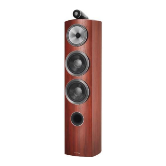
804 D3 Speakers
Produced by: T. Taylor
The contents of this document and associated files contain confidential information that is propriety to Bowers & Wilkins, and
are intended solely for the purpose of servicing the product. The information is intended for use by service technicians familiar
with electronic products. No part of the contents should be supplied or published elsewhere.
Page 1 of 51
© Bowers & Wilkins 2016
Advertisement
Table of Contents

Related Manuals for Bowers & Wilkins 804 D3


Summary of Contents for Bowers & Wilkins 804 D3
-
Page 1: Front Cover
Bowers & Wilkins TECHNICAL SUPPORT Distributor Service Technical Manual 804 D3 Speakers Produced by: T. Taylor The contents of this document and associated files contain confidential information that is propriety to Bowers & Wilkins, and are intended solely for the purpose of servicing the product. The information is intended for use by service technicians familiar with electronic products. -
Page 2: Revision History & 800 Series Tool Kit
Bowers & Wilkins TECHNICAL SUPPORT Revision History Date Revision Details 22 MAR 2016 Initial Release 800 Series Tool Kit The contents of this document and associated files contain confidential information that is propriety to Bowers & Wilkins, and are intended solely for the purpose of servicing the product. The information is intended for use by service technicians familiar with electronic products. -
Page 3: Table Of Contents
Bowers & Wilkins TECHNICAL SUPPORT Content Front Cover Page 1 Revision History & 800 Series Tool Kit Page 2 Content Page 3 Introduction Page 4 Technical Sheet Page 5 1. Tool and Test Equipment Page 6 2. Cosmetic Inspection Page 7 3. -
Page 4: Introduction
Bowers & Wilkins TECHNICAL SUPPORT Introduction Please read this manual carefully before commencing servicing! Only qualified and authorised technicians should attempt to service this product. Antistatic Precautions (ESD) Electronic devices and components are extremely sensitive to electrostatics (ESD). Always observe ESD precautions when handling electronic modules or PCBs. -
Page 5: Technical Sheet
Bowers & Wilkins TECHNICAL SUPPORT Technical Sheet Technical Features: Diamond Tweeter, Continuum Cone FST, Turbine Head, Aerofoil Cone Bass Units, Flow Port, Optomised Matrix and Solid Body Tweeter. Description: 3-way vented-box system Drive units: 1x ø25mm (1 in) diamond dome high-frequency 1x ø130mm (5 in) Continuum cone FST™... -
Page 6: Tool And Test Equipment
1. Tools and Test Equipment The tools listed below in Figure: 1 are required to carry out the initial testing and repair of the 804 D3 Speakers, , the specialized tools are included in the 800 Diamond Tool Kit. Figure: 1... -
Page 7: Cosmetic Inspection
This is visual check and should be done before any work commences to clarify that there is no external damage to the 804 D3 Speaker see Figure: 2. Note: It is recommended that PPE gloves are used for this function. -
Page 8: First Functional Test
Bowers & Wilkins TECHNICAL SUPPORT 3. First Functional Test Confirm the reason for returning the 804 D3 Speakers, carry out a functional test using the equipment shown below in Figure: 3. Figure: 3 4. Basic-wire Connections to Speakers B&W 804D3 have speaker wire connections to allow for bi-amplification or bi-wiring. -
Page 9: Bi-Wiring Connections To Speakers
Bowers & Wilkins TECHNICAL SUPPORT 5. Bi-wiring Connections to Speakers The Bi-wire connection separates the woofer/midrange from the tweeter section. These two sets of terminals allow the speakers to be split into two independent sections. The split connects the mid and high frequency drivers to one set of terminals and the low frequency driver to the other pair. - Page 10 Bowers & Wilkins TECHNICAL SUPPORT Remove the Terminal Links from each speaker (this separates LPF & HPF). Connect each amplifier channel to its respective speaker section as shown in Figure: 6. Set the level controls on the amplifiers such that the signal will arrive at all speaker terminals at the same power-volume level.
-
Page 11: Vertical Bi-Amplification Connection To Speakers
Bowers & Wilkins TECHNICAL SUPPORT b. If present, remove the bi-wire links from each speaker. The Bi-Wire links normally connect the woofer/midrange and tweeter sections. c. Connect each power amplifier channel to its respective speaker section. The amplifier used for bass frequencies would connect to the bass (woofer or low frequency) terminals of each speaker. - Page 12 Bowers & Wilkins TECHNICAL SUPPORT Figure: 7 Note: In this diagram the Left Channels of each Amplifier are wired to the Top binding posts of the corresponding Speakers and the Right Channels to the Bottom binding posts. You can have it opposite with the Right Channels of each Amplifier wired to the Top binding posts of the corresponding Speakers and the Left Channel to the Bottom binding posts.
-
Page 13: 4D3 Mechanical Drawing & Spare Parts List
Bowers & Wilkins TECHNICAL SUPPORT 8. 804D3 Mechanical Drawing & Spare Parts The contents of this document and associated files contain confidential information that is propriety to Bowers & Wilkins, and are intended solely for the purpose of servicing the product. The information is intended for use by service technicians familiar with electronic products. - Page 14 Bowers & Wilkins TECHNICAL SUPPORT 804D3 Spare Parts The contents of this document and associated files contain confidential information that is propriety to Bowers & Wilkins, and are intended solely for the purpose of servicing the product. The information is intended for use by service technicians familiar with electronic products.
- Page 15 Bowers & Wilkins TECHNICAL SUPPORT The contents of this document and associated files contain confidential information that is propriety to Bowers & Wilkins, and are intended solely for the purpose of servicing the product. The information is intended for use by service technicians familiar with electronic products.
-
Page 16: Wiring Diagram For 804D3
Bowers & Wilkins TECHNICAL SUPPORT 9. Wiring Diagram for 804D3 The drawing below shows the wiring for each of the Speakers to the HF & LF Crossovers and the Terminal Tray. Tweeter Molex Plug Mid - Range HF Crossover Assembly Upper Bass Unit LF Crossover Assembly Lower Bass Unit... -
Page 17: Tweeter Motor Disassembly
Bowers & Wilkins TECHNICAL SUPPORT 10. Tweeter & Motor Disassembly To remove the HF Grille it will need pulling forward from the Tweeter housing as shown in Figure: 8. Figure: 8 HF Housing HF Grille Once the gap appears around the HF Grille insert the HF Grille Removal Tool HH37214 into the grille release slot as shown in Figure: 9. - Page 18 Bowers & Wilkins TECHNICAL SUPPORT Now use a 4mm Alen/Hex to unscrew the rear HF Cap as shown in Figures: 10. Figure: 10 HF Housing 4mm Hex/Alen key HF Rear Cap Once the Rear HF Cap is removed the HF Tube is visible shown in Figure: 11. Figure: 11 HF Rear HF Cap HF Tube...
- Page 19 Bowers & Wilkins TECHNICAL SUPPORT Now insert the HF Motor removal tool HH15156 in to the rear of the tweeter, shown in Figure: 13 and then slowly rotate the tool until it locks in to the HF motor. Figure: 13 HF Motor Assy HF Motor Removal Tool –...
- Page 20 Bowers & Wilkins TECHNICAL SUPPORT Figure: 16 HF Housing Internal View Tweeter HF Housing HF Motor Assembly HF Spade Terminal To refit the replacement motor make sure the locating lug is in the correct orientation and aligned with the receiver socket as shown in figure 17. Figure: 17 Thermal Pad HF Locating...
-
Page 21: Tweeter Mechanical Drawing & Parts
Bowers & Wilkins TECHNICAL SUPPORT 11. Tweeter Mechanical Drawing & Parts The contents of this document and associated files contain confidential information that is propriety to Bowers & Wilkins, and are intended solely for the purpose of servicing the product. The information is intended for use by service technicians familiar with electronic products. -
Page 22: Tweeter Unit Removal
Bowers & Wilkins TECHNICAL SUPPORT 12. Tweeter Unit Removal With the Mid - Range Unit Speaker removed (as in section 13) the Tweeter Housing connections can be accessed and disconnected and then removed as shown in Figure: 18. Figure: 18 HF Retaining Nut/Bolt HF Molex Socket &... - Page 23 Bowers & Wilkins TECHNICAL SUPPORT Figure: 20 Figure: 21 HF Cables HF Retaining Molex Plug Bolt Tool Rotate Shaft Note: The Molex Tool may need the shaft rotating to help travel the full distance on the Crimp (take hold of the shaft). Once the 2 x HF Cables have been removed from the Molex Plug carefully thread both of the HF Cables into the HF Retaining Bolt Tool as shown in Figure: 21.
- Page 24 Bowers & Wilkins TECHNICAL SUPPORT It will now be possible to carefully feed the Molex Crimp Pins through the HF Retaining Bolt, the Molex Pins will only go through one at a time. The Tweeter Housing can now be lifted off the Cabinet.as shown in Figure: 23.
-
Page 25: Mid - Range Removal
Bowers & Wilkins TECHNICAL SUPPORT 13. Mid - Range Removal To gain access to the Mid - Range Speaker start by putting your fingers against the Dust Cap, then slowly pull it forwards as shown in Figure: 25. Place the Dust Cap in a safe place for reinsertion on reassembly. - Page 26 Bowers & Wilkins TECHNICAL SUPPORT Figure: 26 Insert Mid Extractor Tool 1 x Nut & Washer Care should be taken in the form of support when the Nut has ben removed as the the Mid – Range Speaker will fall forward as shown in Figure: 27, if not reverse the Mid Extractor Tool HH15121 and remove with the Tool.
- Page 27 Bowers & Wilkins TECHNICAL SUPPORT Figure: 27 Mid – Range Falls Forward Mid-Range removal using the Mid Extractor Tool HH15121 Coil Former Washer The Mid – Range Speaker can now be taken out of its fixing as shown in Figure: 28, take care not to damage the Bass Unit Speaker below.
-
Page 28: Draw Bar Assembly Removal
Bowers & Wilkins TECHNICAL SUPPORT Figure: 29 Wires Brown & Blue Mid - Range Crimp Connectors Mid - Range Speaker Disconnect the 2 x Crimp Connectors and then fit the replacement Mid - Range Speaker in reverse order... 14. Draw Bar Assembly Removal With the Mid –... - Page 29 Bowers & Wilkins TECHNICAL SUPPORT Now remove the 2 x Hex Bolts shown in Figure: 30 and lift the Draw Bar Assembly out of the Cabinet as shown in Figure: 31. Figure: 31 Draw Bar Assembly Once the Sleeve Spring Assembly has been removed from the Cabinet it can be disassembled further by removing the Circlip as shown in Figure: 32.
-
Page 30: Mf Cabinet Tube Removal
Bowers & Wilkins TECHNICAL SUPPORT Note: Although it is possible to disassemble the Rear Isolator from the Drawbar it is recommended that the Rear Isolator remains on the Draw Bar as removing the Draw Bolt Fixing could damage the Draw Bar. Once the Drawbar Assembly has been repaired or a replacement sourced refit in reverse order. -
Page 31: Upper And Lower Base Unit Speaker Removal
Bowers & Wilkins TECHNICAL SUPPORT Note: Aline the Gasket Figure: 35 before refitting the MF Cabinet Tube. Make sure that the Acoustic Foam is still in place, if not push it back in place. Acoustic Foam Fit a new ty-rap to hold the Tweeter Cable Gasket Replace Ty-Rap... - Page 32 Bowers & Wilkins TECHNICAL SUPPORT Figure: 37 Outer Aluminium Outer Aluminium Rim securing Rim securing magnets magnets With the Outer Aluminium Rim removed now unscrew and remove the 8 x Hex Bolts as shown in Figure: 38. 6” Cabinet Tube Figure: 38 8 x Hex Bolts Bass Unit Speaker...
-
Page 33: Upper 6" Cabinet Tube Removal
Bowers & Wilkins TECHNICAL SUPPORT 17. Upper 6” Cabinet Tube Removal Start by removing the 8 x Hex Bolts shown in Figure: 40 and put these to one side for reassembly. Figure: 40 Note: Take care not to drop any of the 8 x Hex Bolts into the Cabinet or scratch the Cabinet Tube. -
Page 34: Lower 6" Cabinet Tube Removal
Bowers & Wilkins TECHNICAL SUPPORT Figure: 42 Note: Aline the Gasket before refitting the Cabinet Tube. Make sure that the Acoustic Foam is still in place, if not push it back in place. Acoustic Foam Gasket Once the 6” Cabinet Tube has been replaced (in reverse order) and following the instruction in section 15 refit the Bass Unit Speaker in reverse order. - Page 35 Bowers & Wilkins TECHNICAL SUPPORT Once all 8 x Hex Bolts have been removed the Cabinet Tube will fall forward as shown in Figure: 44, take care not to damage the Gasket. Figure: 44 Note: Take care not to Gasket damage the Cabinet when lifting the Cabinet Tube away from the...
-
Page 36: Terminal Tray Removal
Bowers & Wilkins TECHNICAL SUPPORT 19. Terminal Tray Assembly Removal Start by removing the 2 x Torx Screws using a Torx size 8 key to unscrew the 2 x Torx screws as shown in Figure: 46. Figure: 46 Terminal Tray 2 x Torx Screws With the 2 x Torx Screws removed the Terminal Tray can be pulled forward which is shown in Figure: 47, this allows access to the Terminal Tray and the crimped wires/ terminals. - Page 37 Bowers & Wilkins TECHNICAL SUPPORT Figure: 48 Exposed Terminal Fixing Unscrew Terminal Cap Using the Terminal Nut Runner Tool HH33782 unscrew the Retaining Nuts on each of the Terminals as shown in Figure: 49. Figure: 49 Terminal Nut Runner Tool When the Terminal Nuts have been removed carefully slide each terminal out the back of the Terminal Tray making sure you retain the 2 x Red and 2 x Black Terminal Isolators as shown in Figure: 47.
-
Page 38: Hf Crossover Assembly Removal
Bowers & Wilkins TECHNICAL SUPPORT 20. HF Crossover Assembly Removal Start by removing the Mid – Range Speaker as in section 12, then remove the Wadding shown in Figure: 50. Figure: 50 Molex Connector Molex Plug Wadding Cut Ty - Rap With the Wadding removed the Molex Connector is visible, pull the Molex Plug out of the Molex Connector (these Red &... - Page 39 Bowers & Wilkins TECHNICAL SUPPORT With the Upper Bass Unit Speaker removed unscrew the 4 x Phillips Screws holding the HF Crossover Assembly in place as shown in Figure: 52. The Mid – Range Speaker Figure: 52 Cable and the Tweeter Cable are both connected to the HF Crossover Assembly.
-
Page 40: Lf Crossover Assembly Removal
Bowers & Wilkins TECHNICAL SUPPORT Figure: 54 HF Crossover Assembly 21. LF Crossover Assembly Removal Start by removing the Upper and Lower Bass Unit Speakers as in section 15. Then remove the 4 x Phillips Screws holding the LF Crossover Assembly in place shown in Figure: 55. - Page 41 Bowers & Wilkins TECHNICAL SUPPORT As the LF Crossover is lifted out the 2 x Crimp connectors from the Upper Bass Unit Speaker will need disconnecting as shown in Figure: 56. Figure: 56 2 x Upper Bass Unit Speaker Crimps LF Crossover Assembly The LF Crossover Assembly can now be replaced in the reverse order, see Figure: 57 to view the complete LF Crossover Assembly.
-
Page 42: Hf Crossover Drawing & Circuit
Bowers & Wilkins TECHNICAL SUPPORT 22. HF Crossover Drawing & Circuit The contents of this document and associated files contain confidential information that is propriety to Bowers & Wilkins, and are intended solely for the purpose of servicing the product. The information is intended for use by service technicians familiar with electronic products. -
Page 43: Hf Parts List
Bowers & Wilkins TECHNICAL SUPPORT 23. HF Parts List The contents of this document and associated files contain confidential information that is propriety to Bowers & Wilkins, and are intended solely for the purpose of servicing the product. The information is intended for use by service technicians familiar with electronic products. -
Page 44: Lf Crossover Drawing & Circuit
Bowers & Wilkins TECHNICAL SUPPORT 24. LF Crossover Drawing & Circuit The contents of this document and associated files contain confidential information that is propriety to Bowers & Wilkins, and are intended solely for the purpose of servicing the product. The information is intended for use by service technicians familiar with electronic products. -
Page 45: Lf Parts List
Bowers & Wilkins TECHNICAL SUPPORT 25. LF Parts List 26. Final Functional Test ( Stethoscope Examination of Speakers) Aim of the Test The stethoscope functional test can quickly reveal any air leaks or flaws following a repair to a loudspeaker. The only sound coming from a loudspeaker enclosure should be from the driver components themselves, not the surfaces or seams of the speaker cabinet. - Page 46 Bowers & Wilkins TECHNICAL SUPPORT Next place the earpieces of the stethoscope in your ears and place the listening tube around the piece on the Speaker Cabinet that you wish to examine. Place the listening tube several inches in front of each driver in a multi-way speaker system you can hear each individual driver to a great extent.
-
Page 47: Cleaning
Bowers & Wilkins TECHNICAL SUPPORT 27. Cleaning The cabinet surfaces will usually only require dusting. If you wish to use an aerosol or other cleaner, apply the cleaner onto the cloth, not directly onto the product and test a small area first, as some cleaning products may damage some of the surfaces. Avoid products that are abrasive, or contain acid, alkali or antibacterial agents. -
Page 48: Product Test List
Bowers & Wilkins TECHNICAL SUPPORT 28. Product Test List: Passive Loudspeakers Sweep Frequency Test 20 Hz – 20 kHz (3 volts, all products) check for distortion & balance between left & right speaker Spot Frequency Test 4 volts – Book shelf 5 volts –... -
Page 49: Test Result Sheet
Bowers & Wilkins TECHNICAL SUPPORT 29. Test Result Sheet: □ In Warranty Reason for return: □ Out of Warranty □ Chargeable PAT Testing Required Date done: Received packaging re-useable - - Yes / No Serial no. 1. Tools and Equipment Required Part Number Description 1 x Amp... - Page 50 Bowers & Wilkins TECHNICAL SUPPORT 5. Speaker Bi-Wiring Check RH/LH speakers are working Bi-wire Yes/No 10. Tweeter & Motor Assembly Does it need replacing? Yes/No (LH/RH or Both) Does the Grille need replacing? Yes/No (LH/RH or Both) 12. Tweeter Unit Assembly Does it need replacing? Yes/No (LH/RH or Both) 13.
- Page 51 Bowers & Wilkins TECHNICAL SUPPORT Review During Service and Testing: Commercial / Sales / Technical Note: Additional parts Customer informed of damage Customer quoted Authorisation: Date: □ Results Recorded Date: Checked by: □ Clean 804D3 Speakers Date: Management Successful completion of repair and all documentation completed Signature: The contents of this document and associated files contain confidential information that is propriety to Bowers &...
Need help?
Do you have a question about the 804 D3 and is the answer not in the manual?
Questions and answers