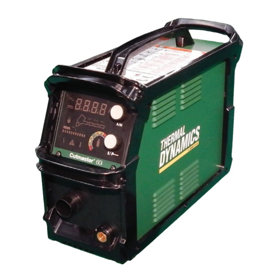
ESAB THERMAL DINAMICS CUTMASTER 60i Operating Manual
Plasma cutting system
Hide thumbs
Also See for THERMAL DINAMICS CUTMASTER 60i:
- Operating manual (129 pages) ,
- Operating manual (58 pages)
Table of Contents

Related Manuals for ESAB THERMAL DINAMICS CUTMASTER 60i


Summary of Contents for ESAB THERMAL DINAMICS CUTMASTER 60i
- Page 1 INPUT POWER INPUT POWER SL60QD OUTPUT MAX OUTPUT VOLTAGE INPUT POWER 208- 400V 480V CUTMASTER® 60i PLASMA CUTTING SYSTEM OPERATING MANUAL Art # A-14029 Revision: AA Issue Date: 25 February, 2019 Manual No.: 0-5561 esab.com...
- Page 2 This product is backed by our extensive warranty and world-wide service network. To locate your nearest distributor or service agency call 1-800-426-1888, or visit us on the web at www.esab.com. This Operating Manual has been designed to instruct you on the correct use and operation of your Thermal Dynamics product.
- Page 3 2800 Airport Rd. Denton, Texas 76207 www.esab.com © Copyright 2019 by Thermal Dynamics an ESAB brand. All rights reserved. Reproduction of this work, in whole or in part, without written permission of the publisher is prohibited. The publisher does not assume and hereby disclaims any liability to any party for any loss or damage caused by any error or omission in this Manual, whether such error results from negligence, accident, or any other cause.
- Page 4 Be sure this information reaches the operator. You can get extra copies through your supplier. CAUTION These INSTRUCTIONS are for experienced operators. If you are not fully familiar with the principles of operation and safe practices for arc welding and cutting equipment, we urge you to read our booklet, “Precautions and Safe Practices for Arc Welding, Cutting, and Gouging,”...
- Page 5 ASSUREZ-VOUS QUE CETTE INFORMATION EST DISTRIBUÉE À L’OPÉRATEUR. VOUS POUVEZ OBTENIR DES COPIES SUPPLÉMENTAIRES CHEZ VOTRE FOUR- NISSEUR. MISE EN GARDE Les INSTRUCTIONS suivantes sont destinées aux opérateurs qualifiés seulement. Si vous n’avez pas une connaissance approfondie des principes de fonctionne- ment et des règles de sécurité...
- Page 6 This Page Intentionally Blank...
- Page 7 Brand name or trade mark Thermal Dynamics Manufacturer or his authorised representative Name, address, telephone No: ESAB Group Inc. 2800 Airport Rd Denton TX 76207 USA Phone: +01 800 426 1888, FAX +01 603 298 7402 The following harmonised standard in force within the EEA has been used in the design: IEC/EN 60974-1:2012 Arc Welding Equipment - Part 1: Welding power sources.
- Page 8 This Page Intentionally Blank...
-
Page 9: Table Of Contents
TABLE OF CONTENTS SECTION 1: GENERAL INFORMATION............11 1.01 Notes, Cautions and Warnings ................. 11 SECTION 1 : INFORMATIONS GÉNÉRALES ........... 13 1.01 Remarques, avertissements et mises en garde ............13 SECTION 2 SYSTEM: INTRODUCTION ............15 2.01 How To Use This Manual ..................15 2.02 Equipment Identification .................. - Page 10 TABLE OF CONTENTS SECTION 4 SYSTEM: OPERATION ............... 31 4.01 Front Panel Controls / Features ................31 4.02 Preparations for Operation ..................34 SECTION 4 TORCH: OPERATION ..............39 4T.01 Torch Parts Selection ....................39 4T.02 Hand Torch Operation ....................39 4T.03 Gouging........................
-
Page 11: Section 1: General Information
CUTMASTER 60i SECTION 1: GENERAL INFORMATION 1.01 Notes, Cautions and Warnings Throughout this manual, notes, cautions, and warnings are used to highlight important information. These highlights are categorized as follows: NOTE! An operation, procedure, or background information which requires additional emphasis or is helpful in efficient operation of the system. - Page 12 CUTMASTER 60i WARNING AVERTISSEMENT 1. Cutting sparks can cause explosion 1. Les étincelles de coupage peuvent or fire. provoquer une explosion ou un 1.1 Do not cut near flammables. incendie. 1.2 Have a fire extinguisher nearby and 1.1 Ne pas couper près des matières ready to use.
-
Page 13: Section 1 : Informations Générales
CUTMASTER 60i SECTION 1 : INFORMATIONS GÉNÉRALES 1.01 Remarques, avertissements et mises en garde Le présent manuel est ponctué de remarques, d’avertissements et de mises en garde qui attirent l’attention sur des informations importantes. Ces repères sont classés comme suit : REMARQUE : Fonction, procédé... - Page 14 CUTMASTER 60i WARNING AVERTISSEMENT 1. Cutting sparks can cause explosion 1. Les étincelles de coupage peuvent or fire. provoquer une explosion ou un incendie. 1.1 Do not cut near flammables. 1.2 Have a fire extinguisher nearby and 1.1 Ne pas couper près des matières ready to use.
-
Page 15: Section 2 System: Introduction
Electronic copies of this manual can also be downloaded at no charge in Acrobat PDF format by go- ing to the ESAB web site listed below and clicking on "Product Support" / "ESAB Documentation": / "Download Library", then navigate to "Plasma Equipment" and then "Manual". -
Page 16: Power Supply Specifications
CUTMASTER 60i 2.04 Power Supply Specifications 2.04.01 1 Phase 60i 208 - 480 VAC 1 Phase Power Supply Specifications Input Power 208 - 480 VAC(187 - 528 VAC), Single Phase, 50/60 Hz Power Supply includes 9' single phase 8AWG 3/C input 1 Phase Input Power Cable cable with NEMA 6-50P Plug. -
Page 17: 2.04.03 Additional Power Supply Specifications
CUTMASTER 60i 60i 400 VAC 3 Phase CCC Power Supply Specifications Input Power 380 - 415 VAC(342 - 456 VAC), 3 Phase, 50/60 Hz Power Supply includes 9' three phase 12AWG 4/C input 3 Phase Input Power Cable cable without plug. Output Current 10 - 60 Amps, Continuously Adjustable Power Supply Gas Filtering... - Page 18 CUTMASTER 60i Generator Recommendations When using generators to power the 60i Plasma Cutting System, the following ratings are a minimum and are to be used along with the ratings listed above. 60i Generator Specifications Generator Output Rating 60i Output Current Arc Characteristic 15 kW Full Limited...
-
Page 19: Input Wiring Specifications
CUTMASTER 60i 2.05 Input Wiring Specifications WARNING Each CutMaster 60i system is a dedicated 1 Phase OR 3 Phase system and cannot be reconfigured to the other. Personal injury could occur if changing the phase is attempted. 2.05.01 1 Phase Input Cable Wiring Requirements 1 Phase CutMaster 60i Power Supply Input Cable Wiring Requirements Input voltage Freq Power Input... -
Page 20: Power Supply Features
CUTMASTER 60i 2.06 Power Supply Features Handle and Leads Wrap Control Panel Torch Leads Receptacle Work Lead Receptacle Art # A-13258 Input Power ON/OFF Switch Input Power Cord Port for Optional Automation Interface Cable Gas Inlet Port Filter Assembly Art # A-13275 INTRODUCTION 0-5561... -
Page 21: Section 2 Torch: Introduction
CUTMASTER 60i SECTION 2 TORCH: INTRODUCTION 15.875" / 403 mm 9.285" / 236 mm 2T.01 Scope of Manual 1.175" / 30 mm This manual contains descriptions, operating 1.375" / 35 mm 4.95" / 126 mm instructions and maintenance procedures for 1.75"... -
Page 22: 04 Quick Connection Torch
CUTMASTER 60i 2T.04 Quick Connection Torch Mechanized Torch Ratings Ambient 104° F The new SL60QD™ (Quick Disconnect) torch allows Temperature 40° C for a quick change of the torch handle assembly from the leads. To change the torch handle assem- 100% @ 100 Amps @ 400 Duty Cycle bly do the following. -
Page 23: Section 3 System: Installation
CUTMASTER 60i SECTION 3 SYSTEM: INSTALLATION 3.01 Unpacking Use the packing lists to identify and account for each item. Inspect each item for possible shipping damage. If damage is evident, contact your distributor and / or shipping company before proceeding with the installation. Record Power Supply and Torch model and serial numbers, purchase date and vendor name, in the information block at the front of this manual. -
Page 24: Primary Input Power Connections
CUTMASTER 60i 3.04 Primary Input Power Connections 3.04.01 1 Phase WARNING Each CutMaster 60i system is a dedicated 1 Phase OR 3 Phase system and cannot be reconfigured to the other. Personal injury could occur if changing the phase is attempted. CAUTION The primary power source, fuse, and any extension cords used must conform to local electrical code and the recommended circuit protection and wiring requirements as specified in Section 2. -
Page 25: Gas Connections
CUTMASTER 60i Connect with a customer supplied grounding cable to the grounding screw near the top rear of the power supply as required by applicable Local and National Codes or local authority having jurisdiction. Grounding screw is identified with this symbol. Customer Supplied Grounding 3.05 Gas Connections... - Page 26 CUTMASTER 60i Installing Optional Single - Stage Air Filter An optional filter kit (7-7507) is recommended for improved filtering with compressed air, to keep moisture and debris out of the torch. Attach the Single - Stage Filter Hose to the Inlet Port 1/4" NPT of the system filter. Attach the Filter Assembly to the filter hose.
- Page 27 CUTMASTER 60i Use customer - supplied fittings to connect the air line to the Filter. A 5/16" (8mm) O.D. smooth tubing should be used with the press in fitting. Outlet Port (OUT) 2-Stage Filter Inlet Port (IN) Two Stage Filter Assembly 5/16 (8mm) Air/Gas...
-
Page 28: Work Lead Connections
CUTMASTER 60i 3.06 Work Lead Connections Connect the Work Lead to the power supply and the work piece. Attach the Dinse type connection of the work lead to the power supply front panel as shown below. Push in and turn clockwise to the right until tight. Connect the work clamp to the workpiece or cutting table. -
Page 29: Section 3 Torch
Any oil or moisture in the air will If necessary, connect the torch to the Power Sup- be visible on the lens. ply. Connect only the ESAB model SL60, SL60QD™ or SL100 / Mechanical Torch to this power supply. 3T.02 Setting Up Mechanical Torch Maximum torch leads length is 100 feet / 30.5 m,... - Page 30 CUTMASTER 60i This Page Intentionally Blank INSTALLATION 0-5561...
-
Page 31: Section 4 System: Operation
CUTMASTER 60i SECTION 4 SYSTEM: OPERATION 4.01 Front Panel Controls / Features See Illustration for numbering Identification Art # A-13250 Numeric Display • Displays software revision at start up • Displays amperage values (Factory default) • Displays error codes • Displays pre-set (preview) maintenance functions AC Indicator Steady light indicates power supply is ready for operation. - Page 32 CUTMASTER 60i Set Mode Indicator Indicator is ON when unit is flowing gas and pressure can be set. Shield Cup In Place Indicator Indicator is Blinking when any of the following are not in place or connected: Shield Cup, ATC leads or Quick Disconnect.
- Page 33 CUTMASTER 60i One of 7 segments will always be on when unit is on. The gas bottle will be illuminated and flash during a gas pressure fault. Bottle will flash when pressure is below a minimum threshold. Bottle will be on continuously when acceptable. Factory default: One, or two segments and gas bottle will be illuminated depending on the gas pressure level.
-
Page 34: Preparations For Operation
CUTMASTER 60i Upper Knob - Amp and Mode Selector Rotate knob to increase or decrease amperage. Indicator is ON when numeric display is showing amperage output. Press and release knob without turning to step through the different Modes. Factory default: ON Numeric display Torch Quick Disconnect Receptacle Torch Leads are connected here by aligning the connectors, pressing in and turning locking ring... - Page 35 CUTMASTER 60i Connect Work Cable Clamp the work cable to the workpiece or cutting table. The area must be free from oil, paint and rust. Connect only to the main part of the workpiece; do not connect to the part to be cut off. Art # A-04509 Power ON Place the Power Supply ON / OFF switch to the ON (right) position.
- Page 36 CUTMASTER 60i Select Cutting Mode Art # A-13251 Press and release the upper knob without turning to enter the mode selection menu. Place the system in one of the four cutting modes available by pressing and releasing the knob until you reach the desired mode.: LATCH .
- Page 37 CUTMASTER 60i Set the gas pressure/flow using the lower knob, 2. Changes will show on the Gas Pressure Interlock. The green indicator in the center is the ideal setting. Each indicator when lit separately is equal to 5 lbs. from the segment next to it. Each will show 5, 10, or 15 lbs or more below or above the ideal.
- Page 38 CUTMASTER 60i This Page Intentionally Blank OPERATION 0-5561...
-
Page 39: Section 4 Torch: Operation
CUTMASTER 60i SECTION 4 TORCH: OPERATION 4T.01 Torch Parts Selection Install the replacement Electrode by pushing it straight into the torch head until it clicks. Depending on the type of operation to be done determines the torch parts to be used. Install the start cartridge and desired tip Type of operation: for the operation into the torch head. - Page 40 CUTMASTER 60i Cut as usual. Simply release the trigger Torch assembly to stop cutting. Follow normal recommended cutting practices as provided in the power supply operator's manual. NOTE! Shield Cup When the shield cup is properly installed, there Standoff Distance 1/8"...
- Page 41 CUTMASTER 60i Trigger The crown shield cup functions best when cutting 3/16 inch (4.7 mm) solid metal with relatively smooth surface. Drag Cutting With a Hand Torch Drag cutting works best on metal 1/4" (6 Trigger Release mm) thick or less. NOTE! For best parts performance and life, always use the correct parts for the type of operation.
-
Page 42: 03 Gouging
CUTMASTER 60i Angle the torch slightly to direct blow- 4T.03 Gouging back particles away from the torch tip (and operator) rather than directly back into it until the pierce is complete. WARNING Be sure the operator is equipped with proper In a portion of the unwanted metal start gloves, clothing, eye and ear protection and that the pierce off the cutting line and then... -
Page 43: 04 Mechanized Torch Operation
CUTMASTER 60i 4T.04 Mechanized Torch Operation Lead Angle The angle between the torch and workpiece Cutting With Mechanized Torch depends on the output current setting and torch travel speed. The recommended lead The mechanized torch can be activated angle is 35°. At a lead angle greater than 45° by remote control pendant or by a remote the molten metal will not be blown out of interface device such as CNC. - Page 44 CUTMASTER 60i For optimum smooth surface quality, the travel speed should be adjusted so that only the leading edge of the arc column produces the cut. If the travel speed is too slow, a rough cut will be produced as the arc moves from side to side in search of metal for transfer.
-
Page 45: 05 Recommended Cutting Speeds With Exposed Tip
CUTMASTER 60i 4T.05 Recommended Cutting Speeds With Exposed Tip CutMaster® 60i With Exposed Tip Type Material: Mild Steel Type Plasma Gas: Air Type Secondary Gas: Single Gas Torch Thickness Out- Amper- Speed (Per Standoff Plasma Gas Flow (SCFH) Pierce Pierce Height Minute) Pressure* Inches mm (Cat. - Page 46 CUTMASTER 60i CutMaster® 60i With Exposed Tip Type Material: Aluminum Type Plasma Gas: Air Type Secondary Gas: Single Gas Torch Thickness Out- Amper- Speed (Per Standoff Plasma Gas Flow (SCFH) Pierce Pierce Height Minute) Pressure* Inches mm (Cat. Volts (Amps) Inches Meters Inches mm Plasma Total** Delay Inches mm No.)
- Page 47 CUTMASTER 60i CutMaster® 60i With Exposed Tip Type Material: Stainless Steel Type Plasma Gas: Air Type Secondary Gas: Single Gas Torch Thickness Out- Amper- Speed (Per Standoff Plasma Gas Flow (SCFH) Pierce Pierce Height Minute) Pressure* Inches mm (Cat. Volts (Amps) Inches Meters Inches mm Plasma Total** Delay Inches mm...
-
Page 48: 06 Recommended Cutting Speeds With Shielded Tip
CUTMASTER 60i 4T.06 Recommended Cutting Speeds With Shielded Tip CutMaster® 60i With Shielded Tip Type Material: Mild Steel Type Plasma Gas: Air Type Secondary Gas: Single Gas Torch Thickness Out- Amper- Speed (Per Standoff Plasma Gas Flow (SCFH) Pierce Pierce Height Minute) Pressure* Inches mm... - Page 49 CUTMASTER 60i CutMaster® 60i With Shielded Tip Type Material: Aluminum Type Plasma Gas: Air Type Secondary Gas: Single Gas Torch Thickness Out- Amper- Speed (Per Standoff Plasma Gas Flow (SCFH) Pierce Pierce Height Minute) Pressure* Inches mm (Cat. Volts (Amps) Inches Meters Inches mm Plasma Total** Delay Inches mm No.)
- Page 50 CUTMASTER 60i CutMaster® 60i With Shielded Tip Type Material: Stainless Steel Type Plasma Gas: Air Type Secondary Gas: Single Gas Torch Thickness Out- Amper- Speed (Per Standoff Plasma Gas Flow (SCFH) Pierce Pierce Minute) Pressure* Height Inches mm (Cat. Volts (Amps) Inches Meters Inches mm Plasma Total** Delay Inches mm...
-
Page 51: Patent Information
CUTMASTER 60i PATENT INFORMATION Plasma Cutting Torch Patents The following parts are covered under U.S. and Foreign Patents as follows: Catalog # Description Patent(s) 9-8215 Electrode US Pat No(s) 6163008; 6987238 Other Pat(s) Pending 9-8213 Cartridge US Pat No(s) 6903301; 6717096; 6936786; 6703581; D496842;... - Page 52 CUTMASTER 60i The following parts are also licensed under U.S. Patent No. 5,120,930 and 5,132,512: Catalog # Description 9-8235 Shield Cap 9-8236 Shield Cap 9-8237 Shield Cup 9-8238 Shield Cap 9-8239 Shield Cap 9-8244 Shield Cap 9-8245 Shield Cap Patents Pending for the following: Quick Disconnect Torch and Quick Disconnect Torch Leads OPERATION 0-5561...
-
Page 53: Section 5 System: Service
CUTMASTER 60i SECTION 5 SYSTEM: SERVICE 5.01 General Maintenance Maintain more often Warning! if used under severe Disconnect input power before maintaining. conditions Each Use Visual check of torch tip and electrode Weekly Visually inspect the cables and leads. Replace as needed Visually inspect the torch body, consumables and Quick Connect 3 Months... -
Page 54: Common Faults
CUTMASTER 60i Six Months or Every 720 Cutting Hours: Check the in-line air filter(s), clean or replace as required. Check cables and hoses for leaks or cracks, replace if necessary. CAUTION Do not blow air into the power supply during cleaning. Blowing air into the unit can cause metal particles to interfere with sensitive electrical components and cause damage to the unit. -
Page 55: Fault Indicator
CUTMASTER 60i 5.04 Fault Indicator At initial power up, the system goes through a series of self checks before it is ready for use. If during those checks it detects something is not within proper operating parameters, a fault will occur. If that happens the Fault indicator will light followed by the Error Code , and number in the digital display. -
Page 56: Basic Troubleshooting Guide
CUTMASTER 60i 5.05 Basic Troubleshooting Guide WARNING There are extremely dangerous voltage and power levels present inside this unit. Do not attempt to diagnose or repair unless you have had training in power electronics measurement and troubleshooting techniques. Problem - Possible Cause Recommended Action Symptom... - Page 57 CUTMASTER 60i Problem - Possible Cause Recommended Action Symptom Nothing happens 1. Problem in the torch and leads switch 1. Take Torch and Leads (Remote Pendant) to Authorized Repair Facility. when torch switch circuit (Remote pendant switch circuit). or remote switch 2.
- Page 58 CUTMASTER 60i Sequence of Operation (Block Diagram) ACTION: ACTION: ACTION: ACTION: ON / OFF switch to ON Close external Select desired Operating mode Set Torch Type and disconnect switch. Lead Length. Select RESULT: RUN, RESULT: SET/PURGE mode AC indicator Power to system. LATCH, GAS indicator Rapid Auto Restart (RAR),...
-
Page 59: Power Supply Basic Parts Replacement
CUTMASTER 60i 5.06 Power Supply Basic Parts Replacement WARNING Disconnect primary power to the system before disassembling the torch, leads, or power supply. This section describes procedures for basic parts replacement. For more detailed parts replacement procedures, refer to the Power Supply Service Manual. Filter Element Assembly Replacement The Filter Element Assembly (9-0116) is in the rear panel. - Page 60 CUTMASTER 60i Optional Single-Stage Filter Element Replacement These instructions apply to power supplies where the optional Single-Stage Filter has been installed. The Power Supply shuts down automatically when the Filter Element becomes completely saturated. The Filter Element can be removed from its housing, dried, and reused. Allow 24 hours for Element to dry.
- Page 61 CUTMASTER 60i WARNING Always turn OFF the air supply and bleed the system before disassembling the Filter Assembly as injury could result. Loosen the two bolts on the top of the Filter Assembly enough to allow the Filter Elements to move freely. Note the location and orientation of the old Filter Elements.
- Page 62 CUTMASTER 60i This Page Intentionally Blank SERVICE 0-5561...
-
Page 63: Section 5 Torch: Service
CUTMASTER 60i SECTION 5 TORCH: SERVICE 5T.01 General Maintenance Upper Groove with Vent Holes Must Remain Open NOTE! Refer to Previous “Section 5: System” for com- Upper O-Ring in Correct Groove mon and fault indicator descriptions. Threads Cleaning Torch Lower O-Ring Art # A-03725 Even if precautions are taken to use only Torch Head O-Ring... -
Page 64: 02 Inspection And Replacement Of Consumable Torch Parts
CUTMASTER 60i Remove the tip. Check for excessive 5T.02 Inspection and Replacement of wear (indicated by an elongated or Consumable Torch Parts oversized orifice). Clean or replace the tip if necessary. WARNING Worn Tip Good Tip Disconnect primary power to the system before disassembling the torch or torch leads. -
Page 65: Section 6: Parts Lists
CUTMASTER 60i SECTION 6: PARTS LISTS 6.01 Introduction Parts List Breakdown The parts list provide a breakdown of all replaceable components. The parts lists are arranged as follows: 6.03 Power Supply Replacement 6.04 Replacement Power Supply Parts 6.05 Options and Accessories 6.06 External Replacement Parts (Plastic) 6.07... -
Page 66: Replacement Power Supply Parts
CUTMASTER 60i 6.04 Replacement Power Supply Parts Description Catalog # Filter Assembly Replacement Element (Factory filter) 9-0116 SINGLE phase Input Power Cord for 208/480 V Power Supply 9-9701 THREE phase Input Power Cord for 208/480 V Power Supply 9-9706 6.05 Options and Accessories Description Catalog #... -
Page 67: External Replacement Parts (Plastic)
CUTMASTER 60i 6.06 External Replacement Parts (Plastic) Item # Description Catalog # Handle, Case Top 9-9702 Bezel, Side Frame RH 9-9703 Handle, CM60i (3 total) 9-9665 Foot, Case Front 9-9694 Bezel, Side Frame LH 9-9704 Foot, Case Rear 9-9693 Screws and nuts can be obtained at a local hardware store. M5x0.8x12mm screw M5x0.8x16mm screw M5x0.8 nut... -
Page 68: Replacement Parts For Hand Torch
CUTMASTER 60i 6.07 Replacement Parts for Hand Torch Item # Description Catalog # SL60QD™ Torch Handle Assembly (PKG) 7-5681 Leads Assemblies with ATC connector and Quick Connectors SL60QD™, 20 - foot Leads Assembly with ATC and QD connectors 4-5620 SL60QD™, 50 - foot Leads Assembly with ATC and QD connectors 4-5650 1&2... -
Page 69: Torch Consumable Parts (Sl60)
CUTMASTER 60i 6.08 Torch Consumable Parts (SL60) 9-8252 9-8218 (60A) 9-8235 9-8243 9-8237 Replace Consumables. 9-8210 Remplacer les consommables. (60A) 8-3487 8-3486 9-8218 9-8281 9-8215 Std Life 9-8214 Black Series 9-8226 B 9-8241 9-8213 9-8237 Torch Head Ext Life (60A) 23x6005 REV AE Art # A-13147_AD 0-5561... -
Page 70: Torch Consumable Parts (Sl100)
CUTMASTER 60i 6.09 Torch Consumable Parts (SL100) 20-40A Shield Tip: Shield Cap, Machine Cup Body, STANDOFF 40A 9-8245 9-8237 CUTTING 9-8205 Shield Cap, Deflector Shield Cup 9-8206 9-8243 9-8218 9-8208 Drag Shield Cup 9-8235 50-60A Shield Tips: STANDOFF Cup Body, CUTTING Shield Cap, Machine 9-8237... -
Page 71: Appendix 1: Data Tag Information
CUTMASTER 60i APPENDIX 1: DATA TAG INFORMATION Manufacturer's Name and/or Hermosillo, Sonora, Mexico Logo, Location, Model and Revision Level, Serial Number Model: and Production Code Date of Mfr: Made in Mexico Type of Power Regulatory Standard Covering 1 or 3 Supply (Note 1) This Type of Power Supply Output Current Type... -
Page 72: Appendix 2: Torch Pin - Out Diagrams
CUTMASTER 60i APPENDIX 2: TORCH PIN - OUT DIAGRAMS Hand Torch Pin - Out Diagram ATC Female Receptacle ATC Male Connector Front View Front View Negative / Negative / Plasma Plasma 8 - Open 8 - Open 4 - Green / Switch 4 - Switch 3 - Switch... -
Page 73: Appendix 3: Torch Connection Diagrams
CUTMASTER 60i APPENDIX 3: TORCH CONNECTION DIAGRAMS Hand Torch Connection Diagram Torch: SL60QD / SL60 / SL100 Hand Torch Leads: Torch Leads with ATC Connector Power Supply: 60i Male ATC Leads ATC Female Connector Receptacle Power Torch Supply Torch Head Leads Black To Power Supply... -
Page 74: Appendix 4: Publication History
CUTMASTER 60i APPENDIX 4: Publication History Cover Date Rev. Change(s) Feb 25, 2019 Release. APPENDIX 0-5561... - Page 75 This Page Intentionally Blank...
- Page 76 Ph +86 21-64072626 Fax: +86 21-64483032 Singapore Sales Office Ph +65 6832-8066 Fax: +65 6763-5812 U.S. Customer Care: 800-426-1888 / FAX 800-535-0557 Canada Customer Care: 905-827-4515 / FAX 800-588-1714 International Customer Care: 940-381-1212 / FAX 940-483-8178 © 2019 ESAB Group Incorporated. www.esab.com...
Need help?
Do you have a question about the THERMAL DINAMICS CUTMASTER 60i and is the answer not in the manual?
Questions and answers