Table of Contents
Advertisement
Available languages
Available languages
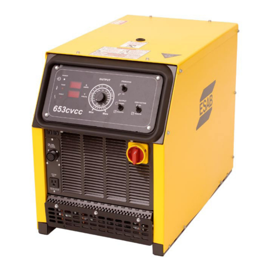
653 cvcc
DC Welding Power Source
Instruction Manual
This manual provides complete instructions for the following power sources starting with Serial No. M0RI603036, January 1996:
ESAB ITEM NO. 37830 - 653cvcc - 230/460/575 vac, 3 ph., 60 Hz
ESAB ITEM NO. 37832 - 653cvcc - 220/400 vac, 3 ph., 50 Hz CE
F15-572-H
02/2006
Advertisement
Table of Contents
Troubleshooting

Subscribe to Our Youtube Channel
Related Manuals for ESAB 653 cvcc


Summary of Contents for ESAB 653 cvcc
- Page 1 This manual provides complete instructions for the following power sources starting with Serial No. M0RI603036, January 1996: ESAB ITEM NO. 37830 - 653cvcc - 230/460/575 vac, 3 ph., 60 Hz ESAB ITEM NO. 37832 - 653cvcc - 220/400 vac, 3 ph., 50 Hz CE F15-572-H...
-
Page 2: User Responsibility
BE SURE THIS INFORMATION REACHES THE OPERATOR. YOU CAN GET EXTRA COPIES THROUGH YOUR SUPPLIER. CAUTION These INSTRUCTIONS are for experienced operators. If you are not fully familiar with the principles of operation and safe practices for arc welding and cutting equipment, we urge you to read our booklet, “Precautions and Safe Practices for Arc Welding, Cutting, and Gouging,”... -
Page 3: Table Of Contents
TABLE OF CONTENTS Section / Title Page Safety Precautions ..................5 Safety - English . - Page 4 TABLE OF CONTENTS...
-
Page 5: Safety Precautions
SECTION 1 SAFETY PRECAUTIONS Safety Precautions Safety - English WARNING: These Safety Precautions are FIRES AND EXPLOSIONS -- Heat from for your protection. They summarize pre- flames and arcs can start fires. Hot cautionary information from the references slag or sparks can also cause fires and listed in Additional Safety Information sec- explosions. - Page 6 SECTION 1 SAFETY PRECAUTIONS 1. Be sure the power source frame (chassis) is con- 3. Welders should use the following procedures to nected to the ground system of the input power. minimize exposure to EMF: 2. Connect the workpiece to a good electrical A.
- Page 7 SECTION 1 SAFETY PRECAUTIONS 5. WARNING: This product, when used for welding 1. Always have qualified personnel perform the instal- or cutting, produces fumes or gases lation, troubleshooting, and maintenance work. which contain chemicals known to Do not perform any electrical work unless you are the State of California to cause birth qualified to perform such work.
- Page 8 SECTION 1 SAFETY PRECAUTIONS 5. AWS C5.5 - "Recommended Practices for Gas Tung- sten Arc Welding“ 6. AWS C5.6 - "Recommended Practices for Gas Metal Arc Welding"“ 7. AWS SP - "Safe Practices" - Reprint, Welding Hand- book. 8. ANSI/AWS F4.1, "Recommended Safe Practices for Welding and Cutting of Containers That Have Held Hazardous Substances."...
-
Page 9: Safety - Spanish
SECTION 1 SEGURIDAD Safety - Spanish La escoria puede estar caliente y desprenderse con velocidad. Personas cercanas deberán usar gafas ADVERTENCIA: Estas Precauciones de Se- de seguridad y careta protectora. guridad son para su protección. Ellas hacen resumen de información proveniente de las FUEGO Y EXPLOSIONES -- El calor de referencias listadas en la sección "Información Adi- las flamas y el arco pueden ocacionar... - Page 10 SECTION 1 SEGURIDAD 1. Asegúrese de que el chasis de la fuente de poder 3. Los soldadores deberán usar los siguientes proced- esté conectado a tierra através del sistema de imientos para minimizar exponerse al EMF: electricidad primario. 2. Conecte la pieza de trabajo a un buen sistema de A.
- Page 11 SECTION 1 SEGURIDAD 5. ADVERTENCIA-- Este producto cuando se uti- 1. Siempre tenga personal cualificado para efec- liza para soldaduras o cortes, tuar l a instalación, diagnóstico, y mantenimiento produce humos o gases, los del equipo. No ejecute ningún trabajo eléctrico a cuales contienen químicos menos que usted esté...
- Page 12 SECTION 1 SEGURIDAD SIGNIFICADO DE LOS SIMBOLOS -- Según usted avanza en la lectura de este folleto: Los Símbolos Sig- nifican ¡Atención! ¡Esté Alerta! Se trata de su seguridad. Significa riesgo inmediato que, de no ser evadido, puede resultar inmediatamente en serio daño personal o la muerte.
-
Page 13: Safety - French
SECTION 1 SÉCURITÉ Safety - French INCENDIES ET EXPLOSIONS -- La chaleur provenant des flammes ou de AVERTISSEMENT : Ces règles de sécurité l'arc peut provoquer un incendie. Le ont pour but d'assurer votre protection. Ils laitier incandescent ou les étincelles récapitulent les informations de précaution provenant des références dans la section peuvent également provoquer un... - Page 14 SECTION 1 SÉCURITÉ 1. Assurez-vous que le châssis de la source 3. Les soudeurs doivent suivre les procédures suivantes d'alimentation est branché au système de mise à pour minimiser l'exposition aux champs électriques la terre de l'alimentation d'entrée. et magnétiques : 2.
- Page 15 SECTION 1 SÉCURITÉ 5. AVERTISSEMENT : Ce produit, lorsqu'il est utilisé ENTRETIEN DE L'ÉQUIPEMENT -- Un équipe- dans une opération de soudage ou de ment entretenu de façon défectueuse ou coupage, dégage des vapeurs ou des inadéquate peut causer des blessures gaz contenant des chimiques consi- graves ou mortelles.
- Page 16 SECTION 1 SÉCURITÉ SIGNIFICATION DES SYMBOLES Ce symbole, utilisé partout dans ce manuel, signifie "Attention" ! Soyez vigilant ! Votre sécurité est en jeu. DANGER Signifie un danger immédiat. La situation peut entraîner des blessures graves ou mortelles. AVERTISSEMENT Signifie un danger potentiel qui peut entraîner des blessures graves ou mortelles.
-
Page 17: Ordering Information
653cvcc, 220/400 (380-415) vac, 3 ph, 50 Hz CE ........37832 ESAB 653cvcc Migmaster Packages The following package includes an ESAB DC power source, wire feeder, 8 ft. (2.4m) control cable, 8 ft. (2.4m) gas hose, .035/.045 in. (.9/1.2mm) feed roll, - 15 ft. (4.5m) GunMaster gas-cooled gun, ®... -
Page 18: Description
SECTION 2 DESCRIPTION 2.1 GENERAL This manual provides information to familiarize the operator with the design, installation and operation of the 653cvcc model power source. DO NOT attempt to install or operate this equipment until you have read and fully understand these instructions. -
Page 19: Optional Accessories
2.4.2 Swivel Mount Kit (Item No. 36172) This kit allows ESAB wire feeders with swivel base mounts to be mounted to the top of the power source on an insulated swivel mount. This allows the feeder to freely rotate, relieving potential wire feed problems while increasing the working area of the torch. - Page 20 SECTION 2 DESCRIPTION...
-
Page 21: Installation
SECTION 3 INSTALLATION 3.1 LOCATION A proper installation site is necessary for the power source to provide dependable service. A proper installation site permits freedom of air movement through the unit while minimizing exposure to dust, dirt, moisture, and corrosive vapors. A mini- mum of 18 inches (46 cm) is required between the side and rear panels of the power source and the nearest obstruction. -
Page 22: Primary (Input) Electrical Connection
SECTION 3 INSTALLATION PRIMARY (INPUT) ELECTRICAL CONNECTION This power source is a three-phase unit and must be connected to a three-phase power supply. It is recommended that the unit be operated on a dedicated circuit to prevent impairment of performance due to an overloaded circuit. ELECTRIC SHOCK CAN KILL! BEFORE MAKING ELECTRICAL INPUT CONNECTIONS TO THE POWER SOURCE, "MACHINERY LOCKOUT PROCEDURES"... - Page 23 SECTION 3 INSTALLATION THE CHASSIS MUST BE CONNECTED TO AN APPROVED ELECTRICAL WARNING GROUND. FAILURE TO DO SO MAY RESULT IN ELECTRICAL SHOCK, SEVERE BURNS OR DEATH. Recommended Cable Strip Lengths C. Thread the properly stripped input and ground conduc- tors through the large strain relief in the rear panel of the power source.
- Page 24 SECTION 3 INSTALLATION E. Figures 3-2, 3-3 & 3-4 illustrate the input voltage terminal board and the input voltage link connections. The particular voltages from which this power source may be operated are stated on the rating plate. The voltage links were factory set for highest voltage stated on the rating plate.
-
Page 25: Output Welding Connections
SECTION 3 INSTALLATION OUTPUT WELDING CONNECTIONS (SECONDARY) BEFORE MAKING ANY CONNECTIONS TO THE POWER SOURCE OUT WARNING PUT TERMINALS, MAKE SURE THAT ALL PRIMARY INPUT POWER TO THE MACHINE IS OFF. The output connections are located on the front panel (Figure 3-5). The negative connection is located at the bottom right corner and the positive (high inductance and low inductance) connections are located at the bottom left corner. - Page 26 The Wire feeder control cable connection is provided by a 19-pin receptacle (J1) located on the left-hand side of the power source front panel. This receptacle will operate all ESAB wire feeders with 19 pin control cables including the Mig 2E, Mig 4HD, Mig 4HD Dual, Mig 5XL, Mig 28A, Mig 35, Digimig, Digimig Dual as well as the UEC-8, Digimatic II and Analog Interface mechanized controls.
- Page 27 SECTION 3 INSTALLATION CVCC 4.1.1 POWER "ON-OFF" SWITCH 3.5.5 3.5.4 3.5.1 WIRE FEEDER CONTROL RECEPTACLE REMOVABLE PANEL 3.5.3 115V ac AUXILIARY RECEPTACLE Negative 3.4, 4.1.7 Output High Inductance for Receptacle STICK WELDING (SMAW) SUBMERGED ARC WELDING (SAW) 3.4, 4.1.7 ARC CUTTING/GOUGING (CAC-A) Low Inductance for MIG WELDING (GMAW) optional MIG WELDING (GMAW)
- Page 28 SECTION 3 INSTALLATION...
-
Page 29: Operation
SECTION 4 OPERATION Never operate the power source with the cover removed. In addition to the safety hazards, improper cooling may cause damage to the CAUTION components. Keep side panels closed when unit is energized. Weld- ing helmet, gloves, and other personal protection should always be worn when welding. - Page 30 SECTION 4 OPERATION 4.1.3 Output Voltage/Current Control This control allows the operator to adjust the output voltage in the CV mode and output current in the CC mode. Placing the Panel/Remote switch in the “Remote” position disables the output control on the front panel. Calibration marks are to provide a rough guide in setting voltage and current.
-
Page 31: Sequence Of Operation
SECTION 4 OPERATION 4.2 SEQUENCE OF OPERATION Prior to performing the steps below, open the wall disconnect switch or remove the fuse from the fuse box to electrically isolate the power source. ELECTRIC SHOCK CAN KILL! "MACHINERY LOCKOUT PROCEDURES" SHOULD BE EMPLOYED. IF IT IS NOT POSSIBLE TO USE PADLOCKS, WARNING ATTACH A RED TAG TO THE LINE DISCONNECT SWITCH OR FUSE BOX WARNING OTHERS THAT THE CIRCUIT IS BEING WORKED ON. - Page 32 SECTION 4 OPERATION F. After setting the desired voltage condition, turn the contactor switch back to the “remote” position. This position requires a remote start control in order to start the welding sequence. NOTE: A PCB and resistor pack discharges capacitor voltage to eliminate the electrode "sparking" or "arcing" potential.
-
Page 33: Maintenance
SECTION 5 MAINTENANCE 5.1 General If this power source does not operate properly, stop work immedi- ately and investigate the cause of the malfunction. Maintenance CAUTION work must be performed by an experienced person, and electrical work by a trained electrician. Do not permit untrained persons to inspect, clean, or repair this power source. -
Page 34: Inspection And Service
SECTION 5 MAINTENANCE 5.3 Inspection and Service Keep the power source dry, free of oil and grease, and protected at all times from damage by hot metal and sparks. 5.3.1 Fan Motor Keep the fan motor free of accumulated dust and lint. 5.3.2 Transformer Other than periodically cleaning the dust and dirt from the transformer, no maintenance is required. -
Page 35: Troubleshooting
SECTION 6 TROUBLESHOOTING 6.1 General DISCONNECT PRIMARY POWER AT WALL SWITCH, OR CIRCUIT WARNING BREAKER, BEFORE ATTEMPTING INSPECTION OR WORK INSIDE THE POWER SOURCE. If the power source is operating improperly, the following troubleshooting information may be used to locate the source of the trouble. -
Page 36: Section 6 Troubleshooting
SECTION 6 TROUBLESHOOTING ELECTRICAL SERVICE AND REPAIR SHOULD BE ATTEMPTED ONLY BY WARNING A TRAINED ELECTRICIAN. Tighten the bolts evenly until finger tight noting that the nuts are not rotating. Tighten the bolts 3/4 turn plus an 1/8 turn using a socket wrench on the bolt heads and rotating only in 1/4 turn incre- ments plus 1/8 turn alternating between the bolts noting that the nuts are not rotating. - Page 37 SECTION 6 TROUBLESHOOTING Table 6-2. Troubleshooting Guide CONDITION ACTION Unit Inoperative No input power. Check main line (user’s) switch fuses — replace if needed. Poor or improper input (terminal board) connections. Defective on/off switch — replace. Thermal light on. Main transformer overheating. Also check for proper cooling, proper primary hookup, or shorted turn on secondary.
- Page 38 SECTION 6 TROUBLESHOOTING...
-
Page 39: Replacement Parts
Ordering To ensure proper operation, it is recommended that only genuine ESAB parts and products be used with this equipment. The use of non-ESAB parts may void your warranty. Replacement parts may be ordered from your ESAB Distributor. - Page 40 SECTION 7 REPLACEMENT PARTS 653cvcc Front Panel View...
- Page 41 SECTION 7 REPLACEMENT PARTS 653cvcc Front Isometric View...
- Page 42 SECTION 7 REPLACEMENT PARTS 653cvcc Internal View...
- Page 43 SECTION 7 REPLACEMENT PARTS 653cvcc Rear Isometric View...
- Page 44 SECTION 7 REPLACEMENT PARTS 653cvcc Internal View...
- Page 45 SECTION 7 REPLACEMENT PARTS 653cvcc Top Internal View...
- Page 46 INSULATOR KYDEX 37890 XFMR MAIN 230/460/575V 37883 INDUCTOR 37907 SCHEMATIC DIAG 653 CVCC 37908 WIRING DIAG SEC 653 CVCC 0558001044 WIRING DIAG PRI 3 PH AFRAME 647361 TERMINAL LUG 672786 BOLT EYE .75-10 X 2.00 950167 GROMMET RUB 1.12 ID X 1.50 GD X .06 W 950905 TERM IL/M .250 TS X 14-16 AWG...
- Page 47 OUTLET 110V SQUARE 954425 LABEL LR-30071 CSA NRTL/C 954506 LABEL ISO 9002 954868 OVERLAY 653 CVCC BLK 954846 LABEL RATING 653 CVCC 230/460/575 954830 LABEL SCHEMATIC 653 2091514 LABEL WARNING WELD AND CUT 2091558 LABEL GND BILK .50 X 1.38 13730632 POT LIN 10K 2W .88L...
- Page 48 SECTION 7 REPLACEMENT PARTS Bill of Materials 653cvcc DC Welding Power Source (Cont'd) ITEM PART OR CODE NO. QTY. DESCRIPTION SYMBOL 0558003579 BRACKET MOUNTING 950466 CAP HOUSING 15 POS 2062348 PLUG HOUSING 9 POS 0558001409 CONNECTION INTERFACE SEAL 9 950125 CONTACT PIN 952609 CONN RECEPT 16 PIN TAFA...
- Page 49 SECTION 7 REPLACEMENT PARTS...
- Page 50 NOTES...
-
Page 51: Revision History
REVISION HISTORY The "A" edition of this booklet includes a rewrite of the primary electrical connection. The "B" edition of this booklet includes: • Schematic and Wiring Diagrams • Additional replacement parts The "C" edition updated part numbers, edited graphics on pages 10 and 12 and removed references to 353cvcc Parts. The "D"... - Page 52 ESAB Welding & Cutting Products, Florence, SC Welding Equipment COMMUNICATION GUIDE - CUSTOMER SERVICES CUSTOMER SERVICE QUESTIONS: Telephone: (800)362-7080 / Fax: (800) 634-7548 Hours: 8:00 AM to 7:00 PM EST Order Entry Product Availability Pricing Order Information Returns ENGINEERING SERVICE:...
Need help?
Do you have a question about the 653 cvcc and is the answer not in the manual?
Questions and answers