
Related Manuals for ESAB Thermal Dynamics CUTMASTER 40


Summary of Contents for ESAB Thermal Dynamics CUTMASTER 40
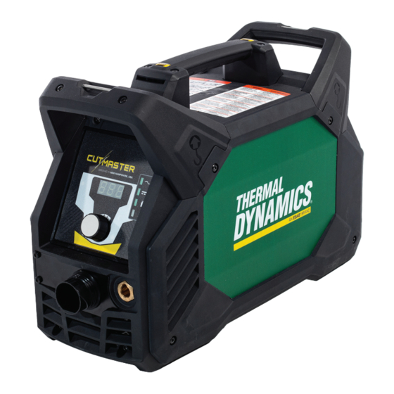
- Page 1 INPUT POWER OUTPUT MAX OUTPUT VOLTAGE 120- 240V CUTMASTER® 40 PLASMA CUTTING SYSTEM OPERATING MANUAL Art # A-14036_AB Revision: AE Issue Date: 29 June, 2020 Manual No.: 0-5557 esab.com...
- Page 2 YOU ARE IN GOOD COMPANY! The Brand of Choice for Contractors and Fabricators Worldwide. Thermal Dynamics is a Global Brand of manual and automation Plasma Cutting Products for ESAB. We distinguish ourselves from our competition through market-leading, dependable products that have stood the test of time. We pride ourselves on technical innovation, competitive prices, excellent delivery, superior customer service and technical support, together with excellence in sales and marketing expertise.
- Page 3 2800 Airport Rd. Denton, Texas 76207 www.esab.com © Copyright 2019 by Thermal Dynamics an ESAB brand. All rights reserved. Reproduction of this work, in whole or in part, without written permission of the publisher is prohibited. The publisher does not assume and hereby disclaims any liability to any party for any loss or damage caused by any error or omission in this Manual, whether such error results from negligence, accident, or any other cause.
- Page 4 Be sure this information reaches the operator. You can get extra copies through your supplier. CAUTION These INSTRUCTIONS are for experienced operators. If you are not fully familiar with the principles of operation and safe practices for arc welding and cutting equipment, we urge you to read our booklet, “Precautions and Safe Practices for Arc Welding, Cutting, and Gouging,”...
- Page 5 ASSUREZ-VOUS QUE CETTE INFORMATION EST DISTRIBUÉE À L’OPÉRATEUR. VOUS POUVEZ OBTENIR DES COPIES SUPPLÉMENTAIRES CHEZ VOTRE FOUR- NISSEUR. MISE EN GARDE Les INSTRUCTIONS suivantes sont destinées aux opérateurs qualifiés seulement. Si vous n’avez pas une connaissance approfondie des principes de fonctionne- ment et des règles de sécurité...
- Page 6 This Page Intentionally Blank...
- Page 7 Type of equipment PLASMA CUTTING SYSTEM Type designation etc. CutMaster 40, from serial number 007-XXXXXX Brand name or trade mark Thermal Dynamics, an ESAB brand Manufacturer or his authorised representative Name, address, telephone No: OZAS-ESAB Ltd. ul. A. Struga 10, 45-073 Opole, Poland Phone: +48 77 4019270, FAX + 48 77 4019 201.
- Page 8 This Page Intentionally Blank...
-
Page 9: Table Of Contents
TABLE OF CONTENTS SECTION 1: GENERAL INFORMATION............11 1.01 Notes, Cautions and Warnings ................. 11 SECTION 1 : INFORMATIONS GÉNÉRALES ........... 13 1.01 Remarques, avertissements et mises en garde ............13 SECTION 2 SYSTEM: INTRODUCTION ............15 2.01 How To Use This Manual ..................15 2.02 Equipment Identification .................. - Page 10 TABLE OF CONTENTS SECTION 5 SYSTEM: SERVICE ..............39 5.01 General Maintenance ....................39 5.02 Maintenance Schedule .................... 39 5.03 Common Faults ......................40 5.04 Fault Indicator ......................41 5.05 Basic Troubleshooting Guide ..................42 5.06 Power Supply Basic Parts Replacement ..............44 SECTION 5 TORCH: SERVICE ..............
-
Page 11: Section 1: General Information
CUTMASTER 40 SECTION 1: GENERAL INFORMATION 1.01 Notes, Cautions and Warnings Throughout this manual, notes, cautions, and warnings are used to highlight important information. These highlights are categorized as follows: NOTE! An operation, procedure, or background information which requires additional emphasis or is helpful in efficient operation of the system. - Page 12 CUTMASTER 40 WARNING AVERTISSEMENT 1. Cutting sparks can cause explosion 1. Les étincelles de coupage peuvent or fire. provoquer une explosion ou un 1.1 Do not cut near flammables. incendie. 1.2 Have a fire extinguisher nearby and 1.1 Ne pas couper près des matières ready to use.
-
Page 13: Section 1 : Informations Générales
CUTMASTER 40 SECTION 1 : INFORMATIONS GÉNÉRALES 1.01 Remarques, avertissements et mises en garde Le présent manuel est ponctué de remarques, d’avertissements et de mises en garde qui attirent l’attention sur des informations importantes. Ces repères sont classés comme suit : REMARQUE : Fonction, procédé... - Page 14 CUTMASTER 40 WARNING AVERTISSEMENT 1. Cutting sparks can cause explosion 1. Les étincelles de coupage peuvent or fire. provoquer une explosion ou un incendie. 1.1 Do not cut near flammables. 1.2 Have a fire extinguisher nearby and 1.1 Ne pas couper près des matières ready to use.
-
Page 15: Section 2 System: Introduction
Electronic copies of this manual can also be downloaded at no charge in Acrobat PDF format by go- ing to the ESAB web site listed below and clicking on "Product Support" / "ESAB Documentation": / "Download Library", then navigate to "Plasma Equipment" and then "Manual". -
Page 16: Power Supply Specifications Csa
CUTMASTER 40 2.04 Power Supply Specifications CSA CM 40 120-240 VAC 1 Phase Power Supply Specifications Input Power 120 - 240 VAC, Single Phase, 50/60 Hz Power Supply includes 9' single phase 12AWG 3/C input cable with NEMA 1 Phase Input Power Cable CSA 6-50P Plug Output Current 15 - 40 Amps, Continuously Adjustable... -
Page 17: Input Wiring Specifications Csa
CUTMASTER 40 2.05 Input Wiring Specifications CSA 1 Phase Input Cable Wiring Requirements 1 Phase CutMaster 40 Power Supply Input Cable Wiring Requirements Input voltage Freq Power Input Suggested Sizes Fuse Flexible Cord Volts I max (amps) (Min. AWG) 120 / 15A 50/60 19.3 13.6... -
Page 18: Power Supply Specifications Ce
CUTMASTER 40 2.06 Power Supply Specifications CE CM 40 240 VAC 1 Phase Power Supply Specifications Input Power 230 VAC, Single Phase, 50 Hz Power Supply includes 2.5M single phase 2.5mm² input 1 Phase Input Power Cable CE cable with Schuko plug Output Current 15 - 40 Amps, Continuously Adjustable Power Supply Gas Filtering Ability... -
Page 19: Generator Recommendations
CUTMASTER 40 2.08 Generator Recommendations When using generators to power the CM40 Plasma Cutting System, the following ratings are a minimum and are to be used along with the ratings previously listed. CM 40 Generator Specifications Generator Output Rating CM 40 Output Current Arc Characteristic 3 kW / 120V 20A on 15A circuit Full... - Page 20 CUTMASTER 40 Gas Inlet Port Input Power ON/OFF Switch Input Power Cord Art # A-14042 Weights and Dimensions 8” 203.29 mm Art # A-14039 12.25" 311.21 mm 18.82" 478.07 mm 29 lb / 13.154 kg Power Supply Dimensions & Weight INTRODUCTION 0-5557...
- Page 21 CUTMASTER 40 Clearances for Operation and Ventilation 15" Art # A-14040 381 mm Ventilation Clearance Requirements 0-5557 INTRODUCTION...
- Page 22 CUTMASTER 40 This Page Intentionally Blank INTRODUCTION 0-5557...
-
Page 23: Section 2 Torch: Introduction
CUTMASTER 40 SECTION 2 TORCH: INTRODUCTION Parts - In - Place (PIP) Torch Head has built - in switch 2T.01 Scope of Manual 15 VDC circuit rating This manual contains descriptions, operating Type Cooling instructions and maintenance procedures for the 1Torch Model SL60™... - Page 24 CUTMASTER 40 This Page Intentionally Blank INTRODUCTION 0-5557...
-
Page 25: Section 3 System: Installation
CUTMASTER 40 SECTION 3 SYSTEM: INSTALLATION 3.01 Unpacking Use the packing lists to identify and account for each item. Inspect each item for possible shipping damage. If damage is evident, contact your distributor and / or shipping company before proceeding with the installation. Record Power Supply and Torch model and serial numbers, purchase date and vendor name, in the information block at the front of this manual. -
Page 26: Gas Connections
CUTMASTER 40 3.03 Gas Connections Connecting Gas Supply to Unit The connection is the same for compressed air or high pressure cylinders. Connect the air line to the quick connect inlet port. The following illustration shows typical gas line with quick connect fittings as an example. Art # A-14048_AB Air Connection to Inlet Port NOTE! -
Page 27: Primary Input Power Connections
CUTMASTER 40 3.04 Primary Input Power Connections CAUTION Check your power source for correct voltage before connecting the unit to input power. The primary power source, fuse, and any extension cords used must conform to local electrical code and the recommended circuit protection and wiring requirements as specified in Section 2. -
Page 28: Work Lead Connections
CUTMASTER 40 3.05 Work Lead Connections Connect the Work Lead to the power supply and the work piece. Attach the Dinse type connection of the work lead to the power supply front panel as shown below. Push in and turn clockwise to the right until tight. Connect the work clamp to the workpiece or cutting table. -
Page 29: Section 3 Torch
INSTALLATION 3T.01 Torch Connections If necessary, connect the torch to the Power Supply. Connect only the ESAB model SL60 or SL60QD™ Torch to this power supply. Maximum torch leads length is 100 feet / 30.5 m, including extensions. WARNING Disconnect primary power at the source before con- necting the torch. - Page 30 CUTMASTER 40 This Page Intentionally Blank INSTALLATION 0-5557...
-
Page 31: Section 4 System: Operation
CUTMASTER 40 SECTION 4 SYSTEM: OPERATION 4.01 Front Panel Controls / Features See Illustration for numbering Identification Art # A-14045 Current Control Knob Knob used to adjust current output. Numeric Display • Displays software revision at start up • Displays amperage values (Factory default) •... -
Page 32: Preparations For Operation
CUTMASTER 40 Gas Pressure Indicator Indicator will be ON to show any gas pressure but not whether it is adequate or not. Check the inlet gas pressure. It should be between 90 - 125 PSI / 6.2 - 8.6 bar / 620 - 862 Kpa. NEVER EXCEED 150 PSI / 10.34 bar / 1034 Kpa. - Page 33 CUTMASTER 40 Connect Work Cable Clamp the work cable to the workpiece or cutting table. The area must be free from oil, paint and rust. Connect only to the main part of the workpiece; do not connect to the part to be cut off. Art # A-04509 Power ON Place the Power Supply ON / OFF switch to the ON (right) position.
- Page 34 CUTMASTER 40 Postflow Release the trigger to stop the cutting arc. Gas continues to flow for approximately 10 seconds. During post - flow, if the user quickly presses and releases the trigger, the gas will shut off. If the user continues to hold the trigger and not release it, the pilot arc starts. The main arc will transfer to the workpiece if the torch tip is within transfer distance.
-
Page 35: Section 4 Torch: Operation
CUTMASTER 40 SECTION 4 TORCH: OPERATION 4T.01 Torch Parts Selection Install the replacement Electrode by pushing it straight into the torch head until it clicks. Depending on the type of operation to be done determines the torch parts to be used. Install the start cartridge and desired tip Type of operation: for the operation into the torch head. - Page 36 CUTMASTER 40 Depending on the cutting operation, do Trigger one of the following: For edge starts, hold the torch per- pendicular to the workpiece with the front of the tip on the edge of Trigger Release the workpiece at the point where the cut is to start.
- Page 37 CUTMASTER 40 Shield Cup With Straight Edge Keep the torch in contact with the work- piece during the cutting cycle. The drag shield cup can be used with a non conductive straight edge to make straight cuts Hold the torch away from your body. by hand.
- Page 38 CUTMASTER 40 Follow normal recommended cutting Slide the trigger release toward the back practices as provided in the power of the torch handle while simultaneous- supply operator's manual. ly squeezing the trigger. The pilot arc will start. NOTE! When the shield cup is properly installed, there is a slight gap between the shield cup and the torch handle.
-
Page 39: 03 Gouging
CUTMASTER 40 4T.03 Gouging Lead Angle The angle between the torch and workpiece WARNING depends on the output current setting and Be sure the operator is equipped with proper torch travel speed. The recommended lead gloves, clothing, eye and ear protection and that angle is 35°. - Page 40 CUTMASTER 40 Rolling Pierce A Rolling Pierce begins cutting with the torch head placed at an angle to the work surface. Splatter/ dross are blown away from the work area as the torch cuts. The torch head rotates towards vertical as the cut grows deeper and pierces the workpiece.
-
Page 41: 04 Patent Information
CUTMASTER 40 4T.04 PATENT INFORMATION Plasma Cutting Torch Patents The following parts are covered under U.S. and Foreign Patents as follows: Catalog # Description Patent(s) 9-8215 Electrode US Pat No(s) 6163008; 6987238 Other Pat(s) Pending 9-8214 Electrode US Pat No(s) 6163008; 6987238 Other Pat(s) Pending 9-8213 Cartridge... - Page 42 CUTMASTER 40 The following parts are also licensed under U.S. Patent No. 5,120,930 and 5,132,512: Catalog # Description 9-8235 Shield Cap 9-8236 Shield Cap 9-8237 Shield Cup 9-8238 Shield Cap 9-8239 Shield Cap 9-8244 Shield Cap 9-8245 Shield Cap Patents Pending for the following: Quick Disconnect Torch and Quick Disconnect Torch Leads TORCH OPERATION 0-5557...
-
Page 43: Section 5 System: Service
CUTMASTER 40 SECTION 5 SYSTEM: SERVICE 5.01 General Maintenance Maintain more often Warning! if used under severe Disconnect input power before maintaining. conditions Each Use Visual check of torch tip and electrode Weekly Visually inspect the cables and leads. Replace as needed Visually inspect the torch body, consumables and Quick Connect 3 Months... -
Page 44: Common Faults
CUTMASTER 40 Six Months or Every 720 Cutting Hours: Check the in-line air filter(s), clean or replace as required. Check cables and hoses for leaks or cracks, replace if necessary. CAUTION Do not blow air into the power supply during cleaning. Blowing air into the unit can cause metal particles to interfere with sensitive electrical components and cause damage to the unit. -
Page 45: Fault Indicator
CUTMASTER 40 5.04 Fault Indicator At initial power up, the system goes through a series of self checks before it is ready for use. If during those checks it detects something is not within proper operating parameters, a fault will occur. If that happens, an Error Code will illuminate on the digital display. -
Page 46: Basic Troubleshooting Guide
CUTMASTER 40 5.05 Basic Troubleshooting Guide WARNING There are extremely dangerous voltage and power levels present inside this unit. Do not attempt to diagnose or repair unless you have had training in power electronics measurement and troubleshooting techniques. Problem - Possible Cause Recommended Action Symptom... - Page 47 CUTMASTER 40 Problem - Possible Cause Recommended Action Symptom Nothing happens 1. Problem in the torch and leads switch 1. Take Torch and Leads (Remote Pendant) to Authorized Repair Facility. when torch switch circuit (Remote pendant switch circuit). or remote switch 2.
-
Page 48: Power Supply Basic Parts Replacement
CUTMASTER 40 5.06 Power Supply Basic Parts Replacement Optional Single-Stage Filter Element Replacement These instructions apply to power supplies where the optional Single-Stage Filter has been installed. The Power Supply shuts down automatically when the Filter Element becomes completely saturated. The Filter Element can be removed from its housing, dried, and reused. -
Page 49: Section 5 Torch: Service
CUTMASTER 40 SECTION 5 TORCH: SERVICE 5T.01 General Maintenance Upper Groove with Vent Holes Must Remain Open NOTE! Refer to Previous “Section 5: System” for com- Upper O-Ring in Correct Groove mon and fault indicator descriptions. Threads Cleaning Torch Lower O-Ring Art # A-03725 Even if precautions are taken to use only Torch Head O-Ring... -
Page 50: 02 Inspection And Replacement Of Consumable Torch Parts
CUTMASTER 40 5T.02 Inspection and Replacement of Remove the tip. Check for excessive wear (indicated by an elongated or Consumable Torch Parts oversized orifice). Clean or replace the tip if necessary. WARNING Worn Tip Good Tip Disconnect primary power to the system before disassembling the torch or torch leads. -
Page 51: Section 6: Parts Lists
CUTMASTER 40 SECTION 6: PARTS LISTS 6.01 Introduction Parts List Breakdown The parts list provides a breakdown of all replaceable components. The parts lists are arranged as follows: 6.03 Power Supply Replacement 6.04 Replacement Power Supply Parts 6.05 Options and Accessories 6.06 External Replacement Parts 6.07... - Page 52 CUTMASTER 40 6.04 Replacement Power Supply Parts Description Catalog # 1 Filter Assembly Replacement Element (Factory filter) 9-0116 1 Cable, Pwr 2.5mm2 3m EU Type F 9-4435 6.05 Options and Accessories Description Catalog # 1 Single - Stage Filter Kit (includes Filter & Hose) 7-7507 1 Replacement Filter Body 9-7740...
- Page 53 CUTMASTER 40 6.06 External Replacement Parts Item # Description Catalog # Top Handle Kit 0464 565 880 Handle Cover 0465 952 001 Panel, RH CM40 TD_AEB 9-4440 Ass'y, Panel Frnt CM40 9-4437 Panel, LH CM40 TD_AEB 9-4439 Ass'y, Panel Rear CM40 9-4438 Top Panel 0465 951 001...
- Page 54 CUTMASTER 40 6.07 Replacement Parts for SL60 Hand Torch Item # Qty Description Catalog # Torch Handle Replacement Kit (includes items No. 2 & 3) 9-7030 Trigger Assembly Replacement Kit 9-7034 Handle Screw Kit (5 each, 6-32 x 1/2” cap screw, and wrench) 9-8062 Torch Head Assembly Replacement Kit (includes items No.
- Page 55 CUTMASTER 40 6.08 Replacement Parts for SL60QD Hand Torch Item # Description Catalog # Torch Handle Assembly Replacement 7-5681 Leads Assemblies with ATC connector and Quick Connectors SL60QD™, 20 - foot Leads Assembly with ATC and QD connectors 4-5620 SL60QD™, 50 - foot Leads Assembly with ATC and QD connectors 4-5650 1&2 Torch and Leads Assembly, 20 - foot 7-5620...
- Page 56 CUTMASTER 40 6.09 Torch Consumable Parts (SL60) Art # A-14049_AC PARTS LIST 0-5557...
-
Page 57: Appendix 1: Data Tag Information
CUTMASTER 40 APPENDIX 1: DATA TAG INFORMATION Manufacturer's Name and/or Regulatory Standard Covering Logo, Location, Model and This Type of Power Supply Revision Level Victor Technologies Group, Inc. 2800 Airport Road Denton, TX 76207 Model: CM40 - CSA/UL Made in Poland Ser. -
Page 58: Appendix 2: Torch Pin - Out Diagrams
CUTMASTER 40 APPENDIX 2: TORCH PIN - OUT DIAGRAMS Hand Torch Pin - Out Diagram ATC Female Receptacle ATC Male Connector Front View Front View Negative / Negative / Plasma Plasma 8 - Open 8 - Open 4 - Green / Switch 4 - Switch 3 - Switch... -
Page 59: Appendix 3: Torch Connection Diagrams
CUTMASTER 40 APPENDIX 3: TORCH CONNECTION DIAGRAMS Hand Torch Connection Diagram Torch: SL60QD / SL60 / SL100 Hand Torch Leads: Torch Leads with ATC Connector Power Supply: CM40 Male ATC Leads ATC Female Connector Receptacle Power Torch Supply Torch Head Leads Black To Power Supply... - Page 60 CUTMASTER 40 This Page Intentionally Blank APPENDIX 0-5557...
- Page 61 This Page Intentionally Blank...
- Page 62 This Page Intentionally Blank...
- Page 63 This Page Intentionally Blank...
- Page 64 ESAB / esab.com...
Need help?
Do you have a question about the Thermal Dynamics CUTMASTER 40 and is the answer not in the manual?
Questions and answers