ESAB POWERCUT 650 Instruction Manual
Portable plasma cutting system
Hide thumbs
Also See for POWERCUT 650:
- Instruction manual (56 pages) ,
- Instruction manual (56 pages) ,
- Instruction manual (56 pages)
Table of Contents
Advertisement
POWERCUT 650
Portable Plasma Cutting System
Instruction Manual (EN)
ESAB Consoles:
ESAB P/N 0558005151 - 230V, 1/3-Phase, 50/60 Hz - "CE"
ESAB P/N 0558005152 - 400V, 3-Phase, 50/60 Hz - "CE"
ESAB P/N 0558007820 - 400V, 3-Phase, 50/60 Hz
0558005362
Tel: +1 843 669 44 11
Fax: +1 843 664 44 58
ESAB AB
SE- - 695 81 LAXÅ
SWEDEN
Phone +46 584 81 000
Fax +46 584 123 08
www.esab.com
030210
Advertisement
Table of Contents
Troubleshooting

Related Manuals for ESAB POWERCUT 650


Summary of Contents for ESAB POWERCUT 650
- Page 1 POWERCUT 650 030210 Portable Plasma Cutting System Instruction Manual (EN) ESAB Consoles: ESAB P/N 0558005151 - 230V, 1/3-Phase, 50/60 Hz - "CE" ESAB P/N 0558005152 - 400V, 3-Phase, 50/60 Hz - "CE" ESAB P/N 0558007820 - 400V, 3-Phase, 50/60 Hz 0558005362...
-
Page 2: User Responsibility
BE SurE tHIS INforMAtIoN rEACHES tHE oPErAtor. You CAN gEt ExtrA CoPIES tHrougH Your SuPPlIEr. CAutIoN these INStruCtIoNS are for experienced operators. If you are not fully familiar with the principles of operation and safe practices for arc welding and cutting equipment, we urge you to read our booklet, “Precautions and Safe Practices for Arc Welding, Cutting, and gouging,”... -
Page 3: Table Of Contents
3.4.1 Primary Electrical Input Connections ....................104 Secondary Connections ........................107 Assembling PT-31XLPC Consumable Parts ...................108 SECtIoN 4 oPErAtIoN .............................109 POWERCUT 650 Controls ........................109 Cutting with the PT-31XLPC .......................111 Operating Techniques ...........................111 Common Cutting Problems ........................113 SECtIoN 5 MAINtENANCE ............................115 Inspection and Cleaning ........................115 Flow Switch ...............................115... - Page 4 tABlE of CoNtENtS...
-
Page 5: Safety
SECtIoN 1 SAfEtY PrECAutIoNS WARNING WARNING Arc welding and cutting can be injurious to yourself and others. Take precausions when welding. Arc welding and cutting can be injurious to yourself and others. Take precausions when welding. Ask for your employer’s safety practices which should be based on manufacturers’ hazard data. Ask for your employer’s safety practices which should be based on manufacturers’... - Page 6 SECtIoN 1 SAfEtY PrECAutIoNS...
-
Page 7: Introduction
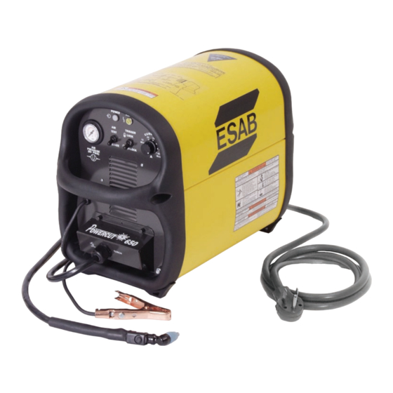
SECtIoN 2 INtroDuCtIoN POWERCUT 650 Cutting Package ® • Manually cuts 15.9mm (5/8 inch) and severs 19.1mm (3/4 inch) - powerful cutting performance • Economical price - tremendous cutting value for the money • Compact portable design - goes to the job, easily moved about •... -
Page 8: General
(6.2-10.3 bar / 90-150 psig). The POWERCUT 650 package uses the PT-31XLPC torch to deliver cutting power for materials up to 15.9mm (5/8-in.) thick or for severing up to 19.1mm (3/4-in.) thick. -
Page 9: Installation
There should be at least one foot of clearance between the POWERCUT 650 power source and wall or any other obstruction to allow freedom of air movement through the power source. -
Page 10: Connections
Be sure that all power is off by opening the line (wall) disconnect switch The POWERCUT 650 power source with 230 vac, 1 / 3 -phase input capability is factory and by unplugging the power cord to the set for 230 vac input. -
Page 11: Section 3 Installation
For 208 vac input, X2 is connected to TB3 and X3 is connected to terminal 3 of D1. Make sure the connections are firmly tightened. Leave all other wires the same. Reinstall cover by sliding it back into the frame rail. Connect the rear handle and connect the Powercut 650 to the 208 vac input power. 208 V CoNfIgurAtIoN NotE: FOR 208 vac MOVE GREY WIRE FROM TB5-2 TO TB5-1, MOVE T1 LEAD X2 TO TB3 AND T1 LEAD X3 TO D1-3. - Page 12 SECtIoN 3 INStAllAtIoN fACtorY SEt for 230 vac INPut Do Not CHANgE ANY otHEr WIrES. X3 HERE FOR 230 vac INPUT GRAY 230 vac X2 HERE FOR 230 vac INPUT INPUT BRIDGE (IBR) BLACK BLACK GRAY rated Input Input & gND fuse Size Conductor Amps...
-
Page 13: Secondary Connections
3.5 SECoNDArY CoNNECtIoNS (rEfEr to fIg. 3.3) WArNINg The POWERCUT 650 is supplied from the factory with the complete PT-31XLPC torch and the work cable with clamp assembly pre-installed. No further instal- lation is required. For information on torch connections or refitting the torch Before making any connections to the (see Sec. -
Page 14: Assembling Pt-31Xlpc Consumable Parts
TION OF HEAT SHIELD. voltage if the torch switch is accidentally closed when the shield is removed. Al- WAYS rEPlACE torCH WItH tHE ProPEr torCH MANufACturED BY ESAB SINCE It AloNE CoNtAINS ESAB’S PAtENtED SAfEtY INtErloCK. figure 3.4 Assembly of “xt” Consumable Parts... -
Page 15: Powercut 650 Controls
A. Power Switch (located on rear panel). When placed in ON position, the white pilot light will glow indicating control circuit is energized and the cooling fan will run. The POWERCUT 650 is now in the "READY" mode given a suitable air supply and a properly assembled torch. -
Page 16: Section 4 Operation
SECtIoN 4 oPErAtIoN H. fault light. Will glow amber under the following conditions and operations will come to a complete stop. flow fault: The fault light will be mostly on but will flick off for approx.1/10th of a second every second. This indicates that the air flow supply is low. Seconds over temperature: The fault light will be mostly off but will flick on for approx. -
Page 17: Cutting With The Pt-31Xlpc
6. In the postflow mode, the arc can be restarted immediately by depressing the WArNINg torch switch. The two second preflow will automatically cancel. Position the PoWErCut 650 at least 10 4.2 oPErAtINg tECHNIquES feet (3 meters) from the cutting area to protect the unit from sparks and hot slag 1. - Page 18 COMING BACK AGAINST AND DAMAG- ING THE TORCH. figure 4.3. Piercing technique using the Pt-31xlPC Cutting Speed range — PoWErCut 650 (using Air with xt Consumables 40A @ 5.2 bar / 75 psig) Nozzle - P/N 0558000512 (20860 ), Electrode - P/N 0558000507 (20862) With 1.6mm (1/16"...
-
Page 19: Common Cutting Problems
Listed below are common cutting problems followed by the probable cause of each. If problems are determined to be caused by the POWERCUT 650, refer to the maintenance section of this manual. If the problem is not corrected after referring to the maintenance section, contact your ESAB representative. - Page 20 SECtIoN 4 oPErAtIoN...
-
Page 21: Maintenance
With all input power disconnected, and wearing proper eye and face protection, blow out the inside of the POWERCUT 650 using low-pressure dry compressed air. 5.1 floW SWItCH (fIgurE 5-1) -
Page 22: Troubleshooting
SECtIoN 5 MAINtENANCE 5.2 trouBlESHootINg WArNINg Check the problem against the symptoms in the following troubleshooting guide. ElECtrIC SHoCK CAN KIll! Be sure that all The remedy may be quite simple. If the cause cannot be quickly located, shut off primary power to the machine has been externally disconnected. -
Page 23: Troubleshooting Guide
SECtIoN 5 MAINtENANCE 5.3 trouBlESHootINg guIDE Difficult Starting. • Change electrode • Change nozzle • Check for good, clean connection of work lead to workpiece • Check air pressure (4.5-5.2 bar / 65-75 psig) • Check torch power cable for continuity Depress torch switch. After 2 seconds, is high frequency present? Repair power Repair/replace source high frequency unit No Air Is air hose connected? Connect Is air adjusted to 4.5-5.2 / 65-75 psig? Adjust... -
Page 24: Section 5 Maintenance
Is air check switch OFF? Turn switch OFF Does arc start when nozzle contacts work without depressing torch switch? Check for short in torch switch Does air flow even when POWERCUT 650 power switch is OFF? Replace Repair power solenoid valve source figure 5-3. - Page 25 Turn on main disconnect Is plug in receptacle? Insert plug in receptacle Is cooling fan turning? Replace pilot light Check voltage at receptacle and input power line Check main fuses Faulty power switch on POWERCUT 650 figure 5-4. Sequence of operations...
- Page 26 • input rating. The light will not turn OFF even when correct voltage is restored. Reset by placing POWERCUT 650 power switch OFF and then ON again. NOTE: When in LOCK-IN mode, the FAULT light will turn on during second...
-
Page 27: Sequence Of Operation
SECtIoN 5 MAINtENANCE 5.4 SEquENCE of oPErAtIoN loCK-IN "off" position RELEASE PUSH TORCH SWITCH OPEN CLOSE GAS SOLENOID VALVE 2 SEC. 10 SEC PREFLOW Postflow CLOSE FLOW SWITCH OPEN FAULT PILOT LIGHT ENERGIZE HF CIRCUIT INVERTER CUTTING ARC (CURRENT) NotES: When the torch switch is pushed during postflow period, the postflow and preflow times are canceled, and the HF is energized immediately. - Page 28 SECtIoN 5 MAINtENANCE loCK-IN "oN" position PUSH RELEASE PUSH RELEASE TORCH SWITCH OPEN CLOSE GAS SOLENOID VALVE PREFLOW 2 SEC. 10 SEC Postflow OPEN CLOSE FLOW SWITCH FAULT PILOT LIGHT ENERGIZE HF CIRCUIT INVERTER CUTTING ARC (CURRENT) NotES: When the torch switch is pushed during postflow period, the postflow and preflow times are canceled, and the HF is energized immediately.
-
Page 29: Re-Fitting The Pt-31Xlpc Torch
SECtIoN 5 MAINtENANCE rE-fIttINg tHE Pt-31xlPC torCH For operator safety, the torch connections are located on the output terminal board behind the lower portion of the front panel. Thread the power cable and switch lead of the PT-31XLPC through the Strain Relief on the Access Cover. - Page 30 SECtIoN 5 MAINtENANCE NotE: Schematics and Wiring Diagrams on 279.4mm x 431.8mm (11” x 17”) paper are included inside the back cover of this manual.
Need help?
Do you have a question about the POWERCUT 650 and is the answer not in the manual?
Questions and answers