Table of Contents
Advertisement
Quick Links
User Manual
GO-5000M-PMCL-UV
CMOS Digital Progressive Scan
Monochrome UV Camera
Document Version: 1.0
GO-5000M-PMCL-UV_Ver.1.0_Feb.2021
Thank you for purchasing this product.
Be sure to read this manual before use.
This manual includes important safety precautions and instructions on how to operate the unit. Be sure to read
this manual to ensure proper operation.
The contents of this manual are subject to change without notice for the purpose of improvement.
© 2021 JAI
Advertisement
Table of Contents

Related Manuals for JAI GO-5000M-PMCL-UV


Summary of Contents for JAI GO-5000M-PMCL-UV
- Page 1 This manual includes important safety precautions and instructions on how to operate the unit. Be sure to read this manual to ensure proper operation. The contents of this manual are subject to change without notice for the purpose of improvement. © 2021 JAI...
-
Page 2: Table Of Contents
GO-5000M-PMCL-UV Contents Notice/Warranty/Certifications Trigger Control Usage Precautions Normal continuous operation Features Timed mode Parts Identifications Trigger width mode RCT mode Preparation Sequence Mode Preparation Process Multi ROI function Step 1: Connecting Devices Operation and function matrix Step 2: Verifying Camera Operation... -
Page 3: Notice/Warranty/Certifications
The material contained in this manual consists of information that is proprietary to JAI Ltd., Japan and may only be used by the purchasers of the product. JAI Ltd., Japan makes no warranty for the use of its product and assumes no responsibility for any errors which may appear or for damages resulting from the use of the information contained herein. - Page 4 GO-5000M-PMCL-UV Supplement The following statement is related to the regulation on “Measures for the Administration of the control of Pollution by Electronic Information Products“ , known as “China RoHS“. The table shows contained Hazardous Substances in this camera. mark shows that the environment-friendly use period of contained Hazardous Substances is 15 years.
-
Page 5: Usage Precautions
GO-5000M-PMCL-UV Usage Precautions Notes on cable configurations The presence of lighting equipment and television receivers nearby may result in video noise. In such cases, change the cable configurations or placement. Notes on attaching the lens Avoiding dust particles When attaching the lens to the camera, stray dust and other particles may adhere to the sensor surface and rear surface of the lens. -
Page 6: Features
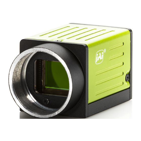
GO-5000M-PMCL-UV Features The GO-5000M-PMCL-UV is an industrial progressive scan camera equipped with a 1-inch global shutter CMOS image sensor with 5.2 effective megapixels (2560 × 2048). This CMOS image sensor has sensitivity in the UV region. The unit is compact and lightweight in design and is equipped with Mini Camera Link interface Supporting a “Power over Camera Link”... -
Page 7: Parts Identifications
GO-5000M-PMCL-UV Parts Identification ① Lens mount(C-mount) Mount a C-mount lens, microscope adapter, etc. here. ❖ Before mounting a lens, be sure to refer to “Step 2:Connecting Devices” and confirm the precautions for attaching a lens and the supported lens types. - Page 8 6(-), 19(+) X_OUT3 Data out 7(+), 20(-) SerTC (RxD) LVDS Serial Control 8(-), 21(+) SerTFG (TxD) 9(-), 22(+) CC1 (Trigger) JAI standard trigger 10(+), 23(-) CC2 (Reserved) 11,24 N.C. 12,25 N.C. 13,14 Shield ④ Camera Link Connector 2 Connect a cable that is compatible with Mini Camera Link (SDR) connectors here.
-
Page 9: Preparation
Later sections of the manual refer to GenICam nomenclature for various features/functions, and includes a complete list of all camera settings starting on Page 54. The GO-5000M-PMCL-UV fully supports applications written using GenICam-based SDKs. The advantage of this is that programs written using GenICam names can be applied with little or no modification to control cameras with other GenICam-compliant interfaces and even GenICam-compliant cameras from different vendors. -
Page 10: Step 1: Connecting Devices
GO-5000M-PMCL-UV Step 1: Connecting Devices ④ Frame grabber board Camera body ③ Camera Link Cable ①Lens ② Direct connection (or MP-45 tripod adapter plate) ① Lens ・C-mount lenses with lens mount protrusions of 10 mm or less can be attached. - Page 11 GO-5000M-PMCL-UV ② Direct connection(or MP-43 tripod adapter plate) When mounting the camera directly to a wall or other device, use screws that match the camera locking screw holes on the camera (M3, depth: 3 mm). Use the supplied screws to attach the tripod adapter plate.
-
Page 12: Step 2: Verifying Camera Operation
Identification” section. Step 3: Verifying the Connection between the Camera and PC Use a short ASCII command to verify whether the GO-5000M-PMCL-UV is properly recognized in your setup. Please install terminal emulator software capable of serial communication to the PC connected to the camera via the frame grabber board. -
Page 13: Step 4: Changing The Camera Settings
GO-5000M-PMCL-UV Step 4: Changing the Camera Settings This section explains how to change settings by describing the procedure for changing the output format as an example. Configuring the Output Format Configure the size, position, and pixel format of the images to be acquired. -
Page 14: Step 5: Adjusting The Image Quality
It can be set in the range from 0 to 2. (0:0dB, 1:6dB, 2:12dB) GainAuto 0:Off, 1:Continuous Adjusting the Black Level The black level can be set in the following range. GO-5000M-PMCL-UV: DigitalAll:-256~ +255 Item Description Short ASCII Command BlackLevelRawAll It can be set in the range from -256 to 255. -
Page 15: Step 6: Saving The Settings
GO-5000M-PMCL-UV Step 6: Saving the Settings The setting values configured will be deleted when the camera is turned off. By saving current setting values to user memory, you can load and recall them whenever necessary. You can save up to three sets of user settings in the camera. (UserSet1 to UserSet3) Memory(Flash) 一時メモリ... - Page 16 GO-5000M-PMCL-UV ■ To load user settings Stop image acquisition. User settings can only be loaded when image capture on the camera is stopped. Specify the storage location (UserSet1 - UserSet3) using the UserSetLoad command and read the settings of the camera.
-
Page 17: Main Functions
GO-5000M-PMCL-UV Main Functions Camera Link Interface — 17 —... - Page 18 Camera Link pixel clock frequency In the GO-5000M-PMCL-UV, the Camera Link pixel clock can be selected from 84.99 MHz, 72.85 MHz, 58.28 MHz, and 48.57 MHz. If the 48.57MHz clock is used, the transfer length through the camera link cable will be extended to 10m for all tap geometries. On the other hand, the frame rate will be reduced (see table).
-
Page 19: Digital In/Out Interface
GO-5000M-PMCL-UV Digital IN/OUT interface In the GO-5000M-PMCL-UV, the software control tool can assign the necessary signals used in the system to digital inputs and outputs. Line Selector In the Line Selector, the following input and output signals can be assigned. - Page 20 GO-5000M-PMCL-UV GPIO GPIO is a general interface for input and output which controls the I/O for trigger signals and other valid signals and pulse generators. By using this interface you can control an external light source, make a delay function for an external trigger signal, or make a precise exposure setting together with a PWC trigger.
-
Page 21: Pulse Generator
GO-5000M-PMCL-UV Pulse Generator The GO-5000M-PMCL-UV has a frequency divider using the sensor clock as the basic clock and one pulse generator. In the Pulse Generator, various Clear settings are connected to GPIO. The following shows the Pulse Generator default settings. In the GO-5000M-PMCL-UV, the sensor pixel clock is 36 MHz for 8-bit, 28.8MHZ for 10-bit and 24 MHZ for 12-bit. - Page 22 GO-5000M-PMCL-UV Pulse Generator Length Set the counter up value for the pulse generator. If Repeat Count value is “0” and if Pulse Generator Clear signal is not input, the pulse generator generates the pulse repeatedly until reaching this counter up value.
- Page 23 GO-5000M-PMCL-UV Pulse Generator Clear Source The following clear source can be selected as the pulse generator clear signal. Pulse Generator Inverter Clear Source Signal can have polarity inverted. Pulse Generator Setting table Note: 1. If Pulse Generator Repeat Count is set to “0”, the pulse generator works in free- running mode.
-
Page 24: Sensor Layout
GO-5000M-PMCL-UV Sensor layout The CMOS sensors used in the GO-5000M-PMCL-UV have the following tap and pixel layout. Camera output format (Tap Geometry) 1X2–1Y 1X2–1Y is a 2-tap readout system specified in GenICam Tap Geometry and it outputs as the following. - Page 25 GO-5000M-PMCL-UV 1X3–1Y 1X3–1Y is a 3-tap readout system specified in GenICam Tap Geometry. 1X4–1Y 1X4–1Y is a 4-tap readout system specified in GenICam Tap Geometry. — 25 —...
- Page 26 GO-5000M-PMCL-UV 1X8–1Y 1X8–1Y is an 8-tap readout system and outputs as follows. — 26 —...
-
Page 27: Output Timing(Horizontal)
GO-5000M-PMCL-UV Output timing(Horizontal) The horizontal frequency is changed by setting the Tap Geometry. — 27 —... - Page 28 GO-5000M-PMCL-UV — 28 —...
- Page 29 GO-5000M-PMCL-UV — 29 —...
- Page 30 GO-5000M-PMCL-UV — 30 —...
- Page 31 GO-5000M-PMCL-UV — 31 —...
-
Page 32: Output Timing(Vertical)
GO-5000M-PMCL-UV Output timing(Vertical) The below figure shows the vertical timing of Camera Link output during continuous trigger operation. However, with 1X8-1Y 10-bit geometry, which is 80-bit configuration, DVAL and Exposure Active, which are normally output to Camera Link spare bits, are not output through the Camera Link interface as data bits are applied to those bits. - Page 33 GO-5000M-PMCL-UV — 33 —...
- Page 34 GO-5000M-PMCL-UV — 34 —...
-
Page 35: Roi(Region Of Interest) Setting
ROI (Region Of Interest) setting In the GO-5000M-PMCL-UV, a subset of the image can be output by setting Width, Height, Offset- X, and Offset-Y. If the height is decreased, the number of lines read out is decreased and as the result, the frame rate is increased. -
Page 36: Acquisition Control
GO-5000M-PMCL-UV Acquisition control With Trigger OFF (free running mode), the default frame rate of the camera is based on the specified ROI. The smaller the ROI, the faster the default frame rate. However, it is possible to specify a free-running frame rate (i.e., no trigger needed) that is slower than the default rate. -
Page 37: Exposure Setting
If the trigger is used, it uses “Frame Start”. The procedure is; 1. Select “Frame Start” in “Trigger Selector” Note: In the GO-5000M-PMCL-UV, only “Frame Start” is available. 2. Select “Timed” or “Trigger Width” in “Exposure Mode”. 3. Set “ON” in “Trigger Mode”. - Page 38 Maximum: 8 seconds (Note – noise may make image unusable after 1 second) ExposureAuto This is a function to control the exposure automatically. It is effective only for Timed. JAI ALC Reference controls the brightness. There are two modes, OFF and Continuous.
-
Page 39: Trigger Control
The following 5 types of Trigger Control are available by the combination of Trigger Selector, Trigger Mode, Exposure Mode and Trigger Option. Trigger Selector Selects the trigger operation. In the GO-5000M-PMCL-UV, only Frame Start is available. Trigger Mode Selects the trigger operation. In the GO-5000M-PMCL-UV, only Frame Start is available. -
Page 40: Normal Continuous Operation
GO-5000M-PMCL-UV Trigger Activation This command can select how to activate the trigger. Rising edge: At the rising edge of the pulse, the trigger is activated. Falling edge: At the falling edge of the pulse, the trigger is activated. Level High:... -
Page 41: Timed Mode
GO-5000M-PMCL-UV Timed mode This mode captures image(s) with a preset exposure time by using the external trigger. An additional setting determines if the trigger pulse can be accepted during the exposure period. Primary settings to use this mode Acquisition Mode = Single frame, Multi-frame or Continuous... -
Page 42: Trigger Width Mode
GO-5000M-PMCL-UV Trigger width mode In this mode, the exposure time is equal to the trigger pulse width. Accordingly, longer exposure times are supported. Additional settings determine if the trigger pulse can be accepted during the exposure period. Primary settings to use this mode... -
Page 43: Rct Mode
GO-5000M-PMCL-UV RCT mode Until the trigger is input, the camera operates continuously and can use auto-gain, if necessary, to control the exposure setting. During this time, FVAL and LVAL are output but DVAL is not output. When the trigger is input, the fast dump is activated to read out the electronic charge very quickly, after which the accumulation and the readout are performed. - Page 44 GO-5000M-PMCL-UV RCT mode together with ALC function RCT mode can use ALC control to ensure that the proper exposure is set when the trigger pulse is input. In this case, the following settings are additionally required to RCT mode settings.
-
Page 45: Sequence Mode
This is a function to capture images in sequence based on preset ROI, Exposure Time, Gain and other parameters in the sequence index table. To use sequence mode, Video Send Mode must be set to “Command Sequence.” In the GO-5000M-PMCL-UV, this is the only sequence mode available. - Page 46 GO-5000M-PMCL-UV Default setting Sequence mode setting Command Note1: In the binning mode, the maximum value is changed. — 46 —...
-
Page 47: Multi Roi Function
GO-5000M-PMCL-UV Multi ROI function This function divides one frame image into a maximum of 5 images vertically and reads out all areas in one frame. In this function, width is the same for all 5 images. In the GO-5000M-PMCL- UV, image overlapping is not possible. - Page 48 GO-5000M-PMCL-UV Multi ROI settings and output image Note: In this mode, the frame grabber board must set its horizontal pixel number to Multi ROI Width and its vertical pixels to Multi ROI Max and the sum of Multi ROI Height.
-
Page 49: Operation And Function Matrix
GO-5000M-PMCL-UV Operation and function matrix — 49 —... -
Page 50: Black Level Control
GO-5000M-PMCL-UV: Black Level All : -256 ~+255 Gain control In the GO-5000M-PMCL-UV, the gain control uses Analog Base Gain and Digital Gain. Analog Base Gain can be set at 0dB, +6dB or +12dB. The digital gain is used for the master gain setting. - Page 51 GO-5000M-PMCL-UV Gain Auto This provides automatic control of the gain level. This is controlled by the command JAI ALC Reference. There are two modes. OFF: Adjust manually. Continuous: Operate the auto gain continuously The following detailed settings are also available.
-
Page 52: Lut
This function can be used to convert the input to the desired output characteristics. The Lookup Table (LUT) has 32 points for setup in GO-5000M-PMCL-UV. The output level is created by applying gain to the input level to achieve the specified output level. -
Page 53: Shading Correction
GO-5000M-PMCL-UV Linear and Dark Compression GO-5000M-PMCL-UV has a dark compression circuit to improve the signal-to-noise ratio in the dark portion of the image. The following drawing is characteristics of linear and dark compression. Shading Correction This function compensates for shading (non-uniformity) caused by the lens or the light source used. -
Page 54: Blemish Compensation
If the blemish compensation is set to ON, the stored data is loaded. The customer can adjust white blemishes but not black blemishes. In the GO-5000M-PMCL-UV, auto gain and auto exposure can be combined to provide a wide ranging automatic exposure control from dark to bright or vice versa. -
Page 55: Hdr(High Dynamic Range)
GO-5000M-PMCL-UV HDR (High Dynamic Range) HDR sensing mode can be set when HDR Mode is set to ON while Exposure Mode is Timed. The parameters to configure dynamic range are HDR_SLOPE Level 1, Level 2, Level 3 and Level 4. -
Page 56: External Appearance And Dimensions
GO-5000M-PMCL-UV External appearance and dimensions — 56 —... -
Page 57: Spectral Response
GO-5000M-PMCL-UV Spectral response — 57 —... -
Page 58: Specifications Table
GO-5000M-PMCL-UV Specifications table Specifications GO-5000M-PMCL-UV Scanning system Progressive scan Synchronization Internal Interface CameraLink Specifications (V.2.0 RC2), Conforming with PoCL specifications Image sensor 1-inch Monochrome CMOS Aspect Ratio Image size(Effective Image) 12.8 (h) x 10.24 (v) mm, 16.39 mm diagonal Pixel size 5 (h) x 5 (v) μm... - Page 59 GO-5000M-PMCL-UV Full pixels 2560 (h) x 2048 (v) 8 ~2560 pixels, 8 pixels/step(1X2-1Y) 8 ~2560 pixels, 8 pixels/step(1X3-1Y) Width 8 ~2560 pixels, 8 pixels/step(1X4-1Y) 8 ~2560 pixels, 8 pixels/step(1X8-1Y) 0 ~2552 pixels, 8 pixels/step(1X2-1Y) 0 ~2552 pixels, 8 pixels/step(1X3-1Y)(Note1) OFFSET X 0 ~2552 pixels, 8 pixels/step(1X4-1Y)
-
Page 60: Appendix
GO-5000M-PMCL-UV Appendix 1. Precautions Personnel not trained in dealing with similar electronic devices should not service this camera. The camera contains components sensitive to electrostatic discharge. The handling of these devices should follow the requirements of electrostatic sensitive components. Do not attempt to disassemble this camera. - Page 61 5. Exportation When exporting this product, please follow the export regulation of your own country. 6. References 1. This manual can and datasheet for GO-5000M-PMCL-UV can be downloaded from www.jai.com 2. Camera control software can be downloaded from www.jai.com — 61 —...
- Page 62 GO-5000M-PMCL-UV 5. Short ASCII Command Communication Protocol This chapter described the communication control protocol based on the short ASCII command as the reference. Communication setting Protocol (Short ASCII Command) Transmit the setting command to camera NN is any kind of command.
- Page 63 GO-5000M-PMCL-UV 5. Command list (Short ASCII command) GenCP Bootstrap Register Technology Specific Bootstrap Register Device Control Image Format Control — 63 —...
- Page 64 GO-5000M-PMCL-UV Acquisition Control — 64 —...
- Page 65 GO-5000M-PMCL-UV Digital I/O Control Analog Control LUT Control Transport Layer Control — 65 —...
- Page 66 GO-5000M-PMCL-UV User Set Control JAI Custom — 66 —...
- Page 67 GO-5000M-PMCL-UV — 67 —...
- Page 68 GO-5000M-PMCL-UV — 68 —...
- Page 69 GO-5000M-PMCL-UV — 69 —...
- Page 70 GO-5000M-PMCL-UV — 70 —...
- Page 71 GO-5000M-PMCL-UV — 71 —...
- Page 72 GO-5000M-PMCL-UV — 72 —...
-
Page 73: User's Record
Model name: …………… Revision: …………… Serial No: …………… Firmware version: …………… For camera revision history, please contact your local JAI distributor. Trademarks • Microsoft and Windows are trademarks or registered trademarks of Microsoft Corporation in the United States and other countries. - Page 74 GO-5000M-PMCL-UV Revision history Revision Date Changes Feb. 2021 1st Draft — 74 —...
Need help?
Do you have a question about the GO-5000M-PMCL-UV and is the answer not in the manual?
Questions and answers