
Subscribe to Our Youtube Channel
Related Manuals for Unipulse F156


Summary of Contents for Unipulse F156
- Page 1 F156 WEIGHING CONTROLLER OPERATION MANUAL 「CC-Link Ver.1.10」 07 JUN. 2012 REV. 1.40...
- Page 2 Please carefully read this operation manual before using the F156 in order to fully deliver excellent performance and proper and safe use.
- Page 3 Safety Precautions Safety Precautions Be sure to read for safety. In order to have an F156 Weighing Controller used safely, notes I would like you to surely follow divide into , and are indicated by the following WARNING CAUTION documents. Notes indicated here are the serious contents related safely. Please use after understanding the contents well.
- Page 4 Safety Precautions WARNING ● Use F156 with correct supply voltage. ● Carefully check wiring, etc. before applying power. ● Do not disassemble the main body for modifications or repair. ● Be sure to use crimp contacts for connection to terminal blocks, and do not to connect bare wires as they are.
- Page 5 - Places with large quantities of dust, salt or iron powder. - Where the main body is directly affected by vibration or shock. ● Do not use it, broken down. ● When you send F156 by repair etc., please take sufficient measures against a shock.
-
Page 6: Table Of Contents
CONTENTS CONTENTS 1.PART NAMES AND FUNCTIONS ..........1 2.CONNECTION ................5 2-1.Load cell Connection ................5 2-1-1.Load cell signals ................... 5 2-1-2.Connecting load cells in parallel ..............6 2-2. CC-Link Interface Connection ..............8 2-3.Console Connection .................. 9 2-4.External Input/Output (Amphenol Connector) Connection ....10 2-5.SI/F Interface Connection ............... - Page 7 CONTENTS 4-3.Actual Load Calibration ................38 4-3-1.Calibration lock release ................38 4-3-2.Host connection ..................39 4-3-3.Decimal place ....................40 4-3-4.Capacity ....................... 41 4-3-5.Minimum scale division ................42 4-3-6.Balance weight ................... 43 4-3-7.Zero calibration ................... 44 4-3-8.Span calibration ..................47 4-3-9.Calibration lock ................... 49 5.WEIGHT DISPLAY ..............50 5-1.Gross and Net Weight •...
- Page 8 CONTENTS 6-12-8.Upper/lower limit comparison 2 .............. 82 6-12-9.Comparison inhibit time / Judging time / Complete output time ..83 6-12-10.Complete output mode ................85 6-12-11.Auto free fall compensation / Auto free fall compensation regulation / Average count of auto free fall compensation / Auto free fall compensation coefficient ..........
- Page 9 CONTENTS 11.THE LIST OF INITIAL SETTING CODE ......134 11-1.Setting Range Details of the Set Value ..........139 12.ERROR CODES ..............144 13.DIMENSIONS ..............146 14.BLOCK DIAGRAM ............147 15.SPECIFICATIONS ............148 15-1.Analog section ..................148 15-2.Setting section ..................148 15-3.Interface ....................149 15-4.General performance ................149 15-5.Accessories ..................
-
Page 10: 1.Part Names And Functions
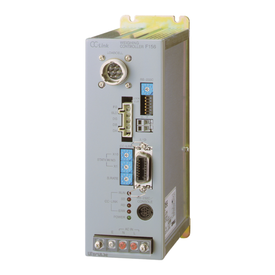
1.PART NAMES AND FUNCTIONS 1.PART NAMES AND FUNCTIONS ◇ Front Panel ① Load cell connector ⑩ RS-232C mode and baud rate setting rotary DIP SW ② CC-Link I/F ⑨ RS-232C communication connector format and memory setting DIP SW ⑧ SI/F interface clamp ③... - Page 11 1.PART NAMES AND FUNCTIONS ① Load cell connector Connect a load cell by using the included connector (female). ② CC-Link I/F connector Connect a CC-Link interface cable by using the included connector (female). ③ CC-Link I/F station number setting rotary DIP SW Set a CC-Link I/F station number with two switches: first and second digits.
- Page 12 Common (insulated power supply ground): ⑧ SI/F interface (clamp connector) This is a 2-wire serial interface to connect UNIPULSE-manufactured printer, external display, etc., which is a nonpolar type, and to which up to three external devices can be connected in parallel.
- Page 13 1.PART NAMES AND FUNCTIONS ⑩ RS-232C mode and baud rate setting rotary DIP SW Set the console mode at 0, and the baud rate in the RS-232C communication mode at 1 – 6 as follows: Rotary switch (mode and baud rate) Mode and baud rate Console mode (C110 or C120) 1200...
-
Page 14: 2.Connection
2.CONNECTION 2. CONNECTION 2-1. Load cell Connection This connector is for connecting a load cell. The adaptable plug is a HIROSE-manufactured JR- 16PK-7S (attached) or its equivalent. +EXC +SIG -SIG SHIELD -EXC Pin No. Signal (6-wire) Signal (4-wire) + EXC +... -
Page 15: Connecting Load Cells In Parallel
2.CONNECTION 2-1-2. Connecting load cells in parallel Some industrial applications require several load cells connected in parallel (e.g., tank or flow scales). A summing junction box should be used to facilitate connection and corner correction. ‘n’ (number) load cells connected in +EXC parallel are considered one unit whose -SIG... - Page 16 10V or more, the load cell may generate heat or be damaged. ・ For connecting a 4-wire load cell to the F156, be sure to connect +EXC and +S, and –EXC and –S. Even if +S and –S are not connected, normal operation will seem to be performed, but the load cell may generate heat or be damaged because excessive voltage is applied.
-
Page 17: Cc-Link Interface Connection
2.CONNECTION 2-2. CC-Link Interface Connection Termination resistance (110Ω) Adaptable cable: KURAMO- manufactured FANC-SB11 or its equivalent Adaptable plug : WAGO 721-105/037-000 (Attachment) Name Signal type Remarks DA side signal line 110Ω termination resistance between them at a bus end DB side signal line Signal line ground Shield Cable shield... -
Page 18: Console Connection
2.CONNECTION 2-3. Console Connection The setting remote console unit (C110/C120) can display all commands, parameter settings, weight values, and status. C110 CONSOLE C120 CONSOLE 0 * #... -
Page 19: External Input/Output (Amphenol Connector) Connection
For input The signal input/output circuit inputs signals by short-circuiting and opening the input and COM terminals. Short circuits are made by contact (relay, switch, etc.) or noncontact (transistor, TTL open collector output, etc.) F156 Open OFF inside Short approx. -
Page 20: F Interface Connection
2.CONNECTION 2-5. SI/F Interface Connection 2-5-1. Connection to a cage clamp type terminal block Connect to the cage clamp type terminal block by using the included mini-screwdriver. 1. Unsheathe the electric wire to be connected 5 – 6mm, and twist its end to such an extent that it will not become loose. -
Page 21: Connection Of External Devices
2.CONNECTION 2-5-2. Connection of external devices This is a 2-wire serial interface to connect a UNIPULSE-manufactured printer, external display, etc., which is a nonpolar type, and to which up to three external devices can be connected in parallel. For connection, use parallel two-core cables, cabtyre cables, and the like. -
Page 22: Rs-232C Interface Connection
2.CONNECTION 2-6. RS-232C Interface Connection Exclusively connect to the same connector on the F156 or this unit as the console. (See "2-3.Console Connection" on p.9) Connector : HOSIDEN TCP8080-01-020 (Attachment) Connector-Pin Assignment Pin No. Signal + 5V (No protection circuit) casing F.G. -
Page 23: 3.Cc-Link Interface
CC-Link network. The F156 is a remote device occupying two stations. In the case of construction with the F156 alone, up to 32 units, including one master, can be connected to the bus. -
Page 24: Outline Of The Buffer Memory For Communication
F156 (remote device station) is called “R” in the explanation. Since one F156 occupies two stations, station numbers are set as shown below when two or more F156s are connected. The upper column and lower column show the buffer name and buffer address (head), respectively. -
Page 25: Buffer Memory Assignments
3.CC-LINK INTERFACE 3-5. Buffer Memory Assignments Data area Remote register M → R (Mitsubishi PLC → F156) Buffer Device Description Station address M → R 01E0H RWw0000 Unused 32bit 01E1H RWw0001 01E2H RWw0002 Unused 32bit 01E3H RWw0003 01E4H RWw0004 Writing data area... - Page 26 3.CC-LINK INTERFACE Remote resistor R → M (F156 → Mitsubishi PLC) Buffer Device Description Station address M → R LSB 02E0H RWr0000 Indicated value (net/gross) 32bit 02E1H RWr0001 02E2H RWr0002 Error code 8bit 02E3H RWr0003 Error assistance code 8bit 02E4H RWr0004 Reading out data area ...
- Page 27 3.CC-LINK INTERFACE Code List Set value writing and operation instructions (R/W relay OFF) Item Code No. Setting Range (RWw0006) (RWw0004~0005) Final 0 to 99999 Set Point 1 0 to 99999 Set Point 2 0 to 99999 Compensation 0 to 9999 Over 0 to 999 Under...
- Page 28 3.CC-LINK INTERFACE Set value writing and operation instructions (R/W relay OFF) continued Item Code No. Setting Range (RWw0006) (RWw0004~0005) Balance Weight 0 to 99999 Capacity 0 to 99999 Minimum Scale Division 1 to 100 Net Over 0 to 99999 Gross Over 0 to 99999 Digital Zero Regulation Value 0 to 9999...
- Page 29 3.CC-LINK INTERFACE Reading out of set value (R/W relay ON) Item Code No. (RWw0006) Final Set Point 1 Set Point 2 Compensation Over Under Upper Limit Lower Limit Near Zero Preset Tare Value Comparison Inhibit Time Judging Time Complete Output Time Adjust Feeding Time (Sequence Mode) Auto Zero Times (Sequence Mode) Judging Times (Sequence Mode)
- Page 30 3.CC-LINK INTERFACE Reading out of set value (R/W relay ON) Item Code No. (RWw0006) Balance Weight Capacity Minimum Scale Division Net Over Gross Over Digital Zero Regulation Value Decimal Place Gravitational Acceleration Lock (Soft) Simple Comparison / Sequence Mode Selection Adjust Feeding in Sequence Mode Near Zero Check in Sequence mode Weight Value Check in Sequence Mode...
- Page 31 3.CC-LINK INTERFACE Remote output (Mitsubishi PLC → F156) Station Buffer Remote Description Class Address Output 0160H RY0000 RY0001 RY0002 Request Use for RY0003 R / W communication RY0004 handshake with RY0005 the host RY0006 RY0007 RY0008 RY0009 RY000A RY000B RY000C...
- Page 32 3.CC-LINK INTERFACE Remote output (Mitsubishi PLC → F156) continued Station Buffer Remote Description Class Address Output 0162H RY0020 Indicated Value Net/Gross Selection RY0021 Feed/Discharge Selection RY0022 Auto Free Fall Compensation Selection RY0023 CPS Write Inhibition Selection RY0024 RY0025 RY0026 RY0027...
- Page 33 3.CC-LINK INTERFACE About RY (Mitsubishi PLC → F156) signals Signal Meaning Request Reads or writes set values or performs operational commands at ON edge. R / W Turns ON to read set values, and OFF to write set values or perform operational commands.
- Page 34 3.CC-LINK INTERFACE Relay domain Remote input (F156 → Mitsubishi PLC) Station Buffer Remote Description Class Address Input 00E0H RX0000 RX0001 RX0002 Response Use for RX0003 R/W (Response) communication RX0004 handshake with RX0005 the host RX0006 CPU Normal Operation RX0007 RX0008...
- Page 35 3.CC-LINK INTERFACE Relay domain Remote input (F156 → Mitsubishi PLC) continued Station Buffer Remote Description Class Address Input 00E2H RX0020 Net/Gross RX0021 Feed/Discharge RX0022 RX0023 RX0024 RX0025 RX0026 RX0027 RX0028 Calibration RX0029 RX002A RX002B RX002C Sequence RX002D RX002E RX002F 00E3H...
- Page 36 Remote output or to Remote register M → R before it is turned ON. Moreover, please conduct initialize process on PLC for access to F156 if they ware turned OFF due to the power failure etc.
-
Page 37: Setting Procedures
3.CC-LINK INTERFACE 3-6. Setting Procedures (The upper and lower levels of each signal correspond to ON and OFF, respectively.) ○ Set value writing or operation instruction timing When the response is OFF, operation is performed at the leading edge of the request. To write set values and to do operation instructions, turn the R/W OFF. - Page 38 3.CC-LINK INTERFACE ○ Operation instruction timing (using special operation instruction bits) Operation instructions can also be given by using the bits from RY0010 to RY0014. The R/W may be either ON or OFF. When tare subtraction is taken as an example, the operation is performed at the tare subtraction edge input.
- Page 39 3.CC-LINK INTERFACE ○ Reading out of set value timing To read set values, turn the R/W ON. Read the reading data area after making sure that the response has turned ON. * When power supply is turned on, please set Request to ON after confirming Remote ready is turned ON.
-
Page 40: Sample Ladder
3.CC-LINK INTERFACE 3-7. Sample Ladder “Sample of incrementing the final value from 0 to 99999” CPU ......A1SH Station No....1 Master slot ....2 “CC-Link System Master/Local Unit User’s Manual (Detailed Information)” Model: AJ/A1SJ61BT11-U In this sample, the final value is written and read by using the request flag, and two values are compared, and if they correspond, the value is incremented, which is repeated up to “99999.”... - Page 41 ] [MOV ] [MOV ] [MOV ] [MOV ] [MOV ] [MOV ] [TO ] *< Remote device F156 occupies 2stations > of PLC start from station 1 M9038 H1201 [MOV ] [TO ] [RST ] M9038 [SET ] [PLS ]...
- Page 42 3.CC-LINK INTERFACE *Up to here initial setting for communication *<RX PLC read value from F156 > M9036 H0E0 [FROM D200 ] > *<RWr PLC read value from F156 M9036 H2E0 D216 [FROM ] > *<Reading out communication status M9036 H6C0 D500 [FROM...
- Page 43 3.CC-LINK INTERFACE * (M101) *<When response turns ON, > request goes OFF M9038 M101 H0FFFB D208 [WAND ] H160 D208 [TO ] *<To M103 > M103 [SET ] M101 [RST ] *Reading out Final value (M103) *<When response goes OFF, >...
- Page 44 3.CC-LINK INTERFACE *Check of communication status (M107) M107 [= D500 H0 ] [= D501 H0 ] [= D502 H0 ] [= D503 H0 ] [= D504 H0 ] [= D505 H0 ] M107 [= D506 H0 ] [= D507 H0 ] [= D508 H0 ] [RST ] *<To M100 > M100 [SET ] *Initialization M9038 M100 [SET ] [RST M101 ] M102 [RST ]...
-
Page 45: 4.Calibration
F156 can exactly display 100.00kg when an actual load (or weight) of 100kg is put on the load cell (scale section) of the weighing machine to which the F156 is connected for example. This operation is called actual load calibration. -
Page 46: Operation Of Actual Load Calibration
4.CALIBRATION 4-2. Operation of Actual Load Calibration To carry out the actual load calibration, follow the procedures given below. Connect the F156 and load cell according to the section Load cell connection “Connection.” Warm-up Lock release Release the calibration lock which locks calibration. -
Page 47: Actual Load Calibration
4-3. Actual Load Calibration 4-3-1. Calibration lock release The F156 has a calibration inhibiting (Lock) function which prevents entered calibration data from unintentional change. This Lock must be released calibrating. Set 49 “Lock (Soft)” in the setting code to “0.”... -
Page 48: Host Connection
4.CALIBRATION 4-3-2. Host connection ① Establish a CC-Link network by using a CC-Link master module, such as Mitsubishi MELSEC-A, PLC, etc. ② Establish a console or RS-232C serial interface with a host computer, etc. Console operation......P103 RS-232C format........ P125... -
Page 49: Decimal Place
3) Determine the setting with the ENT key. Decimal place Not only weight values but also other register addresses of the F156 are not given the notion of decimal place. For example, to set the capacity at 100.00 and the minimum scale division at 0.01, set 10000 and 1, and then the decimal... -
Page 50: Capacity
4.CALIBRATION 4-3-4. Capacity Set the maximum capacity of the scale. If the registered value is exceeded by 10 scale divisions or more, display shows over scale “OFL2”. Setting range / 00000 to 99999 Initial value / 10000 CC-Link Write the code No. and set value. Word size remote register RWw0006... -
Page 51: Minimum Scale Division
4.CALIBRATION 4-3-5. Minimum scale division Set the minimum unit for weighing (scale division). The value of (capacity ÷ minimum scale division) is the resolution of the display. Set a value so that the resolution of the display becomes 10000 or less. Setting range / 001 to 100 CC-Link Write the code No. -
Page 52: Balance Weight
4.CALIBRATION 4-3-6. Balance weight Preset the value of the load (weight) to be applied to the load cell during span calibration. Setting range / 00000 to 99999 Initial value / 10000 CC-Link Write the code No. and set value. Word size remote register RWw0006 Code No. -
Page 53: Zero Calibration
4.CALIBRATION 4-3-7. Zero calibration Adjust the initial zero point. CC-Link Write the code No. and set value. Word size remote register RWw0006 Code No. give an edge input. Remote output RY001B Edge input Console 1) Select code 90. 2) Press the ENT key, and then start fine zero adjustment. - Page 54 4.CALIBRATION When a calibration error is displayed, take measures according to the error message, and do zero calibration again. CC-Link Console 1 - 2 …The initial tare is above the Zero adjustment range. Remove any excess load from load cell or scale. If cErr2 is still displayed, connect a resistor between +EX and -SIG load cell connections.
- Page 55 4.CALIBRATION *For reference, the relationship between the values of resistance connected and input signals is shown in the table below. Resistance Strain Calculated value approx. value μ-STRAIN mV/V 875 kΩ 866 kΩ 437 kΩ 442 kΩ 291 kΩ 294 kΩ 219 kΩ...
-
Page 56: Span Calibration
4.CALIBRATION 4-3-8. Span calibration Calibrates the span with a weight on. CC-Link Write the code No. Word size remote register RWw0006 Code No. give an edge input. Remote output RY001C Edge input Console 1) Select code 91. 2) Press the ENT key, and then span calibration starts. - Page 57 …The output of the load cell is over the span adjustment range. Check to see if the load cell is correctly loaded, and the output of the load cell is within the span adjustment range of the F156. 1 - 9 …The weight value is not stable.
-
Page 58: Calibration Lock
4.CALIBRATION 4-3-9. Calibration lock Upon completion of zero calibration and span calibration, disable changing of calibrated values to prevent them from being changed carelessly. Lock switch ON position on the front panel LOCK Or, set 49 “Lock (Soft)” in the setting code to “1.” Now, changing of calibrated values is disabled. -
Page 59: 5.Weight Display
5.WEIGHT DISPLAY 5. WEIGHT DISPLAY 5-1. Gross and Net Weight • Tare Weight The F156 allows weighing by switching the weight between gross and net. The relationship between the gross and net weight is as follows: GROSS = TARE +... -
Page 60: Weight Value Reading
5.WEIGHT DISPLAY 5-2. Weight Value Reading Range / -99999 to 99999 CC-Link First, select net or gross. Then, read the weight value. Setting / 0 : Net 1 : Gross Write 0 or 1. Remote output RY0020 Word size Read the weight value. remote register RWr0001 32bit... -
Page 61: 6.Functions
6.FUNCTIONS 6. FUNCTIONS 6-1. Tare Subtraction Tare subtraction This function zeros the net weight. This operation does not change the gross weight. Input TARE ON, or set the tare subtraction command. CC-Link Write the code No. or give an edge input. Word size remote register RWw0006... -
Page 62: Preset Tare Weight
6.FUNCTIONS 6-2. Preset Tare Weight This function subtracts a preset tare value from the net weight. This function works when a weight value to be subtracted is input for a tare setting in setting code 09, and tare setting selection in setting code 24 is valid. Preset tare value Setting range / 00000 to 99999 CC-Link... - Page 63 6.FUNCTIONS Preset tare weight Setting / 1 : Valid 0 : Invalid CC-Link Write the code No. and set value. Word size remote register RWw0006 Code No. RWw0005 RWw0004 0 or 1 Set value Console 1) Select code 24. 2) Press the ENT key, and then set the preset tare weight.
-
Page 64: Digital Zero Regulation Value
6.FUNCTIONS 6-3. Digital Zero Regulation Value Set a range of zero point adjustment (a gap from the registered Zero Calibration value) by digital zero or zero tracking. If digital zero operation is performed or zero tracking is actuated where the digital zero regulation value is exceeded, the “zero alarm” status turns on, and the digital zero regulation value is subtracted from the gross weight. -
Page 65: Digital Zero
6.FUNCTIONS 6-4. Digital Zero Digital zero setting This function forces the gross weight to be zeroed. However, if this operation is performed where the weight value exceeds the DZ regulation value in setting code 45, the “zero alarm” status turns ON. The net weight changes according to the following expression: (Net weight) = (Gross weight) –... -
Page 66: Motion Detection
6.FUNCTIONS 6-5. Motion Detection Set the parameters for detecting stability. When the condition of the weight value, varying under the preset range, continues for the preset time or more, the weight value is regarded as stable, and the STAB status turns ON. At each time of A/D conversion, D in the following figure and the range are compared, and if the preset range is exceeded, the STAB status turns OFF. - Page 67 6.FUNCTIONS CC-Link <Period> Write the code No. and set value. Word size remote register RWw0006 Code No. RWw0005 RWw0004 0 to 99 Set value <Range> Write the code No. and set value. RWw0006 Code No. RWw0005 RWw0004 0 to 99 Set value Console 1) Select code 31.
-
Page 68: Zero Tracking
6.FUNCTIONS 6-6. Zero Tracking This function automatically corrects slow zero drifts and micro-movements of the zero point caused by residue remaining after weighing. CC-Link <Period> Write the code No. and set value. Word size remote register RWw0006 Code No. RWw0005 RWw0004 0 to 99 Set value... - Page 69 6.FUNCTIONS ・Zero tracking is the function to reset gross weight to zero automatically when the state remaining the zero point drift within the zero tracking range continues more than set period. ・ Zero tracking period must be set between 0.1 ~ 9.9 second and its range must be set between 0 ~ 99 using 1/4 resolution interval of weight display.
-
Page 70: Gravitational Acceleration
6.FUNCTIONS 6-7. Gravitational Acceleration This function corrects weight errors caused by the difference in local gravitational acceleration when the calibration location and installation location of the scale are different. No setting is required if the calibration location and installation location are in the same area. CC-Link Write the code No. -
Page 71: Digital Filter
6.FUNCTIONS 6-8. Digital Filter This function minimizes instability of the weight value through moving average of A/D- converted data. The number of times of moving average can be selected in the range of 2 - 256. The larger the number of times of moving average, the more the weight value becomes stable, but the slower the response becomes. -
Page 72: Analog Filter
6.FUNCTIONS 6-9. Analog Filter This is a low-pass filter to eliminate noise components from input signals from the load cell, and also stabilize the weight value by averaging. Select the cutoff frequency from 2Hz, 4Hz, 6Hz and 8Hz. By lowering the cutoff frequency, the display becomes more stable, but the response worsens. On the contrary, the higher the frequency, the better the response becomes, but the more difficult it is to make the display stable. -
Page 73: Net Over
6.FUNCTIONS 6-10. Net Over This function gives a warning when the net or gross weight exceeds a fixed regulation value. Conditional expressions and indications are as follows: Conditional expression Net over Net weight > Net over set value Gross over Gross weight >... -
Page 74: Gross Over
6.FUNCTIONS 6-11. Gross Over CC-Link Write the code No. and set value. Word size remote register RWw0006 Code No. RWw0005 00000 to 99999 RWw0004 Set value Console 1) Select code 44. 2) Press the ENT key, and then set the gross over. -
Page 75: Discharging Control Mode
The discharging control means the control method for discharging raw material from the hopper or tank. F156 enables to discharge accurate quantity with the proper combination of setting the control of Final, Set Point 2, Set Point 1, Compensation and Judging Over, Under, Go and Timer for Comparison Inhibit, Judging. - Page 76 Completion of discharge is confirmed with the Near Zero signal. In weighing from the second time onward, (1) ~ (5) are repeated. The feeding valves and discharge valves should be opened and closed through the sequencer or relay sequence according to the control signals from the F156.
- Page 77 6.FUNCTIONS Over Final Final – CPS Under Final – SP2 Final – SP1 Near Zero TIME Tare subtraction Comparison Inhibit Timer Judging Timer Near Zero Judgment (Go, Over or Under)...
- Page 78 2, respectively. The discharge valves are to be completely closed at the time of Final - Compensation, when one measurement is completed. When the weighing tank runs short, the feeding valves are to be opened to replenish the weighing tank with raw materials from the material tank to weigh. F156...
- Page 79 The feeding valves and discharge valves should be opened and closed through the sequencer or relay sequence according to the control signals from the F156.
- Page 80 6.FUNCTIONS Gross for Upper/Lower limit comparison and Near Zero comparisons, and Net for Final and Over/Under. GROSS (In discharging weighing, Net is compared negatively. Final and Over/Under comparisons are made in net weight irrespective of the setting.) Raw materials are fed until the upper limit signal is output.
-
Page 81: Control Mode
6.FUNCTIONS 6-12-2. Control mode Setting / 3 : External selection (CC-Link) 1 : Discharge control 2 : External selection ( 0 : Feed control External Control Input) CC-Link Word size Write the code No. and set value. remote register RWw0006 Code No. -
Page 82: Simple Comparison Control And Sequence Control
6.FUNCTIONS 6-12-3. Simple Comparison Control and Sequence Control Simple Comparison Control Compares weight value with discharging value regulerly. Output is always ON when the weight value satisfies the conditions of final discharging setting items. In simple comparison control, the next weighing is judged to be possible when the weight falls short of 25% of the Final after completion of the previous weighing. - Page 83 6.FUNCTIONS Simple comparison mode / Sequence mode The control method is selected. Setting / 1 : Sequence mode 0 : Simple comparison mode CC-Link Write the code No. and set value. Word size remote register RWw0006 Code No. RWw0005 RWw0004 0 or 1 Set value Console 1) Select code 50.
-
Page 84: Final / Set Point2 / Set Point1 / Compensation / Over / Under
6.FUNCTIONS 6-12-4. Final / Set point2 / Set point1 / Compensation / Over / Under These settings are for controlling and judging feed/discharge. ex) Simple comparison mode Weight Upper limit Final Over Final - CPS Under Final - Set point 2 Final -... - Page 85 6.FUNCTIONS Signal Conditional formula Near zero Weight value ≦ set value of Near zero Set point 1 Weight value ≧ Final - Set point 1 Set point 2 Weight value ≧ Final - Set point 2 Set point 3 Weight value ≧ Final - CPS Under Weight value <...
- Page 86 6.FUNCTIONS CC-Link Write the code No. and set value. Word size remote register RWw0006 ×× Code No. 000 to 999 RWw0005 0000 to 9999 RWw0004 00000 to 99999 Set value Console 1) Code 00 Final Code 01 Code 02 Set point 1 Code 03 Set point 2 Code 04...
-
Page 87: Upper Limit / Lower Limit / Near Zero
6.FUNCTIONS 6-12-5. Upper limit / Lower limit / Near zero These settings are for feed/discharge control, and direct comparisons are made with these values irrespective of the final value. Setting range and code No. of each set value Set value Setting range Code No. -
Page 88: Over/Under Comparison / Upper/Lower Limit Comparison
6.FUNCTIONS 6-12-6. Over/under comparison / Upper/lower limit comparison 1 / Near zero comparison For each comparing point such as final, the comparing weight (gross or net) and timing can be selected. The following three items are selectable. 1) Over/under comparison Select the weight value for Over/under comparison. - Page 89 6.FUNCTIONS CC-Link Write the code No. and set value. Word size remote register RWw0006 ×× Code No. RWw0005 RWw0004 0 to 2 Set value Console 1) Select code 20, 21, and 22. Over/Under Comp. 2) Press the ENT key, and then set the com- Upper/Lower Comp.
-
Page 90: Over/Under Comparison Mode
6.FUNCTIONS 6-12-7. Over/under comparison mode Setting / 3 : Comparison, holding the weight value, when the complete output is ON 2 : Comparison when the complete output is ON 1 : Comparison when the external judgment input is ON 0 : Continuous comparison CC-Link Write the code No. -
Page 91: Upper/Lower Limit Comparison 2
6.FUNCTIONS 6-12-8. Upper/lower limit comparison 2 Setting / 1 : Comparison when the external judgment input is ON 0 : Continuous comparison CC-Link Write the code No. and set value. Word size remote register RWw0006 Code No. RWw0005 RWw0004 0 or 1 Set value Console 1) Select code 28. -
Page 92: Comparison Inhibit Time / Judging Time / Complete Output Time
6.FUNCTIONS 6-12-9. Comparison inhibit time / Judging time / Complete output time Comparison inhibit time / judging time These functions inhibit comparison for a fixed period so that control and judgment will not be operated inappropriately due to mechanical vibrations caused by opening and closing of valves. Final -... - Page 93 6.FUNCTIONS Setting range and code No. of each set value Set value Setting range Code No. Initial value Comparison 000 – 999 inhibit time Judging time (0.00 – 9.99 sec) Complete output time CC-Link Write the code No. and set value. Word size remote register RWw0006...
-
Page 94: Complete Output Mode
6.FUNCTIONS 6-12-10. Complete output mode Set the timing to output the complete signal. Parameters that determine the timing are the judging time and stable signal. Setting 2 : Output by the complete output time after the judging time is up or from when the weight value has become stable with the SP3 signal ON 1 : Output by the complete output time from when the weight value has become stable after the judging time is up with the SP3 signal ON... -
Page 95: Auto Free Fall Compensation
6.FUNCTIONS 6-12-11. Auto free fall compensation / Auto free fall compensation regulation / Average count of auto free fall compensation / Auto free fall compensation coefficient The auto free fall compensation function automatically corrects variations in free fall, which is a great factor of weight errors, for accurate weighing. - Page 96 6.FUNCTIONS Example) Final 20.000 Auto free fall compensation regulation 0.100 Average count of auto free fall compensation Auto free fall compensation coefficient Times Actual weighing Error Average count of AFFC. ← Power ON 20.050 +0.050 0.500 20.040 +0.040 0.500 20.070 +0.070 0.500 20.080...
- Page 97 6.FUNCTIONS ◇ Auto free fall parameter setting Auto free fall compensation 2 : External selection (CC-Link) 1 : Valid 0 : Invalid Select whether or not to use the auto free fall compensation function. (Code No 25 ) Auto free fall compensation regulation 00000 to 99999 Initial value : 9800 Set a regulation value to prevent the compensation value from...
- Page 98 6.FUNCTIONS CC-Link For the auto free fall compensation regulation, Word size write the code No. and set value. remote register RWw0006 Code No. RWw0005 00000 to 99999 RWw0004 Set value For other cases, write the code No. and set value as shown below. Word size remote register RWw0006...
- Page 99 6.FUNCTIONS 〈Auto free fall compensation〉 Console 1) Select code 25. 2) Press the ENT key to enter the settings. 3) Determine the setting with the ENT key. Auto free fall compensation 〈Auto free fall compensation regulation / Average count of auto free fall compensation / Auto free fall compensation coefficient〉...
-
Page 100: Sequence Control
6.FUNCTIONS 6-13. Sequence Control 6-13-1. Normal sequence (with judgment) Over Final Under Final - CPS Final - SP2 Final - SP1 Near zero Time Tare subtraction Start Stop Complete Judgment (Over or Go or Under) Comparison inhibit time Judging time Complete output time Hold Near zero... - Page 101 6.FUNCTIONS ● The complete signal output timing depends on the setting of the complete output mode of setting code 26. ● Over/under comparisons are made, holding the weight value, when the complete output is ON, deregarding the setting of over/under comparison mode of setting code 27. ●...
- Page 102 6.FUNCTIONS Near Zero confirmation at the sequence mode Setting for confirming whether Near Zero signal ON at the start of weighing. Weighing will normally start if the Near Zero is ON. “Sequence error 4” is displayed if the Near Zero is OFF. Refer to "6-12-5.Upper limit / Lower limit / Near zero"...
- Page 103 6.FUNCTIONS Weight value confirmation at the sequence mode Confirm whether the weighing value has reached SP1 at the start of weighing. (select from ON or OFF) If it has, “Sequence error 5” will be displayed. Refer to "6-12-4.Final / Set point2 / Set point1 / Compensation / Over / Under" on p.75 concerning Set Point 1 setting.
-
Page 104: Sequence With Adjust Feeding Valid
6.FUNCTIONS 6-13-2. Sequence with adjust feeding valid Start Stop Complete Judgment (Over or Go) Comparison inhibit time Judging time Adjust feeding time Complete output time ● Set adjust feeding ON/OFF in the sequence mode of setting code 51 to ON. ●... - Page 105 6.FUNCTIONS Adjust feeding time et the adjust feeding time. Set value Setting range Code No. Initial value Adjust feeding 000 to 999 time (0.00 to 9.99 Sec.) CC-Link Write the code No. and set value. Word size remote register RWw0006 Code No.
- Page 106 6.FUNCTIONS Adjust feeding at the sequence mode Determines whether adjust feeding is valid or invalid. Setting / 1 : Valid 0 : Invalid CC-Link Write the code No. and set value. Word size remote register RWw0006 Code No. RWw0005 RWw0004 0 to 1 Set value Console 1) Select code 51.
-
Page 107: Sequence Without Judgment
6.FUNCTIONS 6-13-3. Sequence without judgment Start Stop Complete Comparison inhibit time Complete output time ● Over/under judgment is not made when the setting of the number of judging times of setting code 15 is 00. ● The complete signal is output at the OFF edge (ON → OFF) of the final (SP3) signal deregarding the setting of the complete output mode of setting code 26. -
Page 108: About The Stop Signal
6.FUNCTIONS 6-13-4. About the stop signal Start Stop Sequence error sErr2 ● When the stop signal turns ON, all of the SP1, SP2 and SP3 output signals turn OFF. ● If the start signal is inputted when the stop signal is on the ON level (the sequence stop by external control input or RY0019 by CC-Link communication is ON), sequence error 1 will result. -
Page 109: Relationship Between Auto Zero Times, Judging Times
6.FUNCTIONS 6-13-5. Relationship between auto zero times, judging times, and auto free fall compensation Start AZ times 3 times Auto zero Complete Judging times 2 times Judgment Average count of auto free fall compensation 2 times Auto free fall compensation ●... - Page 110 6.FUNCTIONS Auto zero times / judging times Set the number of auto zero times and the number of judging times in the sequence mode. Set value Setting range Code No. Initial value AZ times 00 to 99 (0 to 99 times) Judging times * When the number of auto zero times is set at zero, the auto zero at start-time becomes invalid.
-
Page 111: Sequence Error
6.FUNCTIONS 6-13-6. Sequence Error If the sequence start signal is input under conditions that weighing cannot be performed properly, or if the stop signal is inputted during weighing, a sequence error occurs, and weighing cannot be started until it is canceled. For details of each error, see "12.ERROR CODES" on p.144. -
Page 112: 7.Remote Console Unit
7.REMOTE CONSOLE UNIT 7. REMOTE CONSOLE UNIT A remote console unit covers all of the F156’s functions. It can suitably be used until startup of a CC-Link system, etc. Console display rate Sets the number of times by which the indicated value is updated per second on the remote console unit. -
Page 113: C110 Operation
7.REMOTE CONSOLE UNIT 7-1. C110 Operation Monitor mode Gross (-sign, 5-digit, decimal place, zero suppression) Net (-sign, 5-digit, decimal place, zero suppression) Tare weight (-sign, 5-digit, decimal place, zero suppression) CC-Link settings (baud rate, station No.) Firmware version Checksum data... - Page 114 7.REMOTE CONSOLE UNIT Setting mode Settings Set value Code Commands (Standby) Dummy zero Code Commands (Flashing) (Waiting for execution) Dummy zero Command (zero calibration) * When no operation is performed for one minute or more in the setting mode, the monitor mode is restored automatically.
- Page 115 7.REMOTE CONSOLE UNIT Monitor change Change the display with the key.
- Page 116 7.REMOTE CONSOLE UNIT Reading out of set value Press the key to switch between the monitor mode and setting mode. Change the lower digit of the setting code with the key, and the higher digit with key. Set value change After inputting the setting code, start changing with the key, shift the digit with the key, change the value with the...
- Page 117 7.REMOTE CONSOLE UNIT Command execution (zero calibration for example) Press the key for the command, and then execute it with the key again. To stop executing the command, press the key. (Standby) (Waiting for execution) If the command normally If a calibration error occurs ends in a few seconds in a few seconds (Repeats the gross and “C.Err*...
-
Page 118: C120 Operation
7.REMOTE CONSOLE UNIT 7-2. C120 Operation Monitor mode Gross (-sign, 5-digit, decimal place, zero suppression) Net (-sign, 5-digit, decimal place, zero suppression) Tare weight (-sign, 5-digit, decimal place, zero suppression) CC-Link settings (baud rate, station No.) Firmware version Checksum data... - Page 119 7.REMOTE CONSOLE UNIT Setting mode Settings Set value Code Commands (Standby) Dummy zero Code Commands (Flashing) (Waiting for execution) Dummy zero Command (zero calibration)
- Page 120 7.REMOTE CONSOLE UNIT Monitor change to 9 Change the display with the keys.
- Page 121 7.REMOTE CONSOLE UNIT Reading out of set value * Press the key to switch between the monitor mode and setting mode. Press numerical keys twice to determine the setting code. Set value change # Input the setting code, start changing with the key, register the value and shift the digit *...
- Page 122 7.REMOTE CONSOLE UNIT Command execution (zero calibration for example) # # Press the key for the command, and then execute it with the key again. * To stop executing the command, press the key. (Standby) # * (Waiting for execution) #...
-
Page 123: Mode Tree Chart
7.REMOTE CONSOLE UNIT 7-3. Mode Tree Chart * Monitor mode Setting mode 10 : Comparison d0 : Gross weight 00 : Final inhibit time d1 : Net weight 01 : Set point 1 11 : Judging time 12 : Complete d2 : Tare weight 02 : Set point 2 output time... - Page 124 7.REMOTE CONSOLE UNIT ・You can move between the lines with the keys(C110), or between the lines with numerical keys (C120) sequentially. 20 : Over/Under 50 : Simple comparison/ 30 : Digital filter 40 : Balance weight comparison sequence mode selection 21 : U/L limit 31 : Motion detection 51 : Adjust feeding...
- Page 125 7.REMOTE CONSOLE UNIT 60 : External control 70 : External control 80 : Tare subtraction 90 : Zero calibration output selection 0 input selection 0 61 : External control 71 : External control 81 : Tare reset 91 : Span calibration output selection 1 input selection 1 62 : External control...
-
Page 126: 8.External Input/Output (Amphenol Connector)
8.EXTERNAL INPUT/OUTPUT (Amphenol Connector) 8. EXTERNAL INPUT/OUTPUT (Amphenol Connector) The external input/output signals are selective. Select necessary signals and set them to each port. However, in the case of redundant settings to input signals, operation is performed as follows: - For the timing of edge operation Functional operation is performed at the edge of any of the input ports assigned with the same signal. -
Page 127: Output (Meanings Of Signals)
8.EXTERNAL INPUT/OUTPUT (Amphenol Connector) Input assignments Pin No. Port Setting code Initially-specified signal External control input 0 0 (Digital zero reset) External control input 1 1 (Digital zero) External control input 2 2 (Tare subtraction) External control input 3 3 (Tare reset) External control input 4 4 (Hold or Judge) Setting... -
Page 128: Input (Meanings Of Signals)
8.EXTERNAL INPUT/OUTPUT (Amphenol Connector) 8-3. Input (Meanings of Signals) ・Digital zero reset (Edge input) Resets the zero point correction value by digital zero at the ON edge, and also cancels the zero alarm if it has occurred. ・Digital zero (Edge input) Zeros the gross value at the edge input. - Page 129 8.EXTERNAL INPUT/OUTPUT (Amphenol Connector) ・Sequence stop (Edge input, Level input) Valid only in sequence mode. Resets the sequence error at the ON edge. If the sequence has already been in execution, the sequence will stop and sequence error 2 will newly occur. The sequence start is inhibited on the ON level.
-
Page 130: 9.Si/F 2-Wire Serial Interface
Each display and printer can select the data individually. ● About the auto print command The F156 can output the auto print command to the printer or display connected to the SI/F. The auto print command is output when the complete signal turns ON. Therefore, if the final... - Page 131 SI/F G/N selection Irrespective of this setting, information including net weight, gross weight, and tare weight is always sent from the F156, and some devices connected to the SI/F allow selection of the weight value displayed/printed on the device side. In such a case, this setting is validated by setting the weight...
-
Page 132: 10.Rs-232C Interface
10.RS-232C INTERFACE 10. RS-232C INTERFACE 10-1. Communication Settings Through the RS-232C interface, you can read indicated values and write set values. Decide the communication mode with the rotary switch and DIP SW on the main body. Rotary switch (mode and baud rate) Mode and baud rate Console mode (C110 or C120) 1200 bps... -
Page 133: Connector Pin Assignments
An example of cabling for a DTE terminal, such as a PC, is given below. Changes may be made depending on the equipment to be connected. For details, see the instruction manual of the equipment to be connected. F156 PC, etc. TCP8080-01-020... -
Page 134: Communication Format
10.RS-232C INTERFACE 10-3. Communication Format ○ Reading out of the gross weight (sign, 5-digit weight, decimal place) Host + . F156 ○ Reading out of the net weight (sign, 5-digit weight, decimal place) Host + . F156 ○ Reading out of the tare weight (sign, 5-digit weight, decimal place) Host R... - Page 135 10.RS-232C INTERFACE ○ Status 2 (7-digit) Host R F156 1 : ON 1 : ON Comp- lete 0 : OFF 0 : OFF 1 : ON 1 : ON Over 0 : OFF 0 : OFF 1 : ON 1 : ON 0 :...
- Page 136 10.RS-232C INTERFACE ○ Status 4 (7-digit) Host R F156 1 : ON 1 : ON Weight error Battery 0 : OFF 0 : OFF 1 : ON EXC alarm 0 : No error Sequence 0 : OFF error 1 to 5 : Error * For details, refer to "12.ERROR CODES"...
- Page 137 10.RS-232C INTERFACE ○ Writing of a set value Example) Final value Host W * No data is returned. F156 Set value No 5-digit set value (no decimal place) ○ Command Example) Tare subtraction Host C * No data is returned.
-
Page 138: List Of Set Value
10.RS-232C INTERFACE 10-4. List of Set Value Final Over Under Upper limit Lower limit Near zero Preset tare value Comparison inhibit time Judging time Complete output time... - Page 139 10.RS-232C INTERFACE Adjust feeding time Auto zero times Judging times Auto free fall compensation coefficient Average count of auto free fall compensation Auto free fall compensation regulation Over/Under comparison U/L limit comparison Near zero comparison Feed/discharge control mode Preset tare weight Auto free fall compensation Complete output mode...
- Page 140 10.RS-232C INTERFACE Over/Under comparison mode U/L limit comparison mode Digital filter Motion detection (period) Motion detection (range) Zero tracking (period) Zero tracking (range) Analog filter Console display rate (LCD) SI/F G/N selection Balance weight Capacity Minimum scale division Net over...
- Page 141 10.RS-232C INTERFACE Gross over Digital zero regulation value Decimal place Gravitational acceleration Lock (Soft) Simple comparison / Sequence mode selection Adjust feeding in sequence mode Near zero check in sequence mode Weight value check in sequence mode External control output selection 0 External control output selection 1 External control output selection 2 External control output selection 3...
-
Page 142: List Of Command
10.RS-232C INTERFACE External control output selection 5 External control output selection 6 External control input selection 0 External control input selection 1 External control input selection 2 External control input selection 3 External control input selection 4 10-5. List of Command Zero calibration Digital zero C... -
Page 143: 11.The List Of Initial Setting Code
11.THE LIST OF INITIAL SETTING CODE 11. THE LIST OF INITIAL SETTING CODE Setting Value Setting Function Initial SOFT LOCK NOV. Page CODE value LOCK number Final 000.00 P.75 000.00 P.75 000.00 P.75 00.00 P.75 Over 0.00 P.75 Under 0.00 P.75 Upper limit 000.00... - Page 144 11.THE LIST OF INITIAL SETTING CODE Setting Function Initial SOFT LOCK NOV. Page CODE value LOCK number Over/Under comparison P.79 ○ ○ U/L limit comparison P.79 ○ ○ Near zero comparison P.79 ○ ○ Feed/discharge control P.72 ○ ○ mode Preset tare weight P.54 ○...
- Page 145 11.THE LIST OF INITIAL SETTING CODE Setting Function Initial SOFT LOCK NOV. Page CODE value LOCK number Simple comparison / P.73 ○ ○ Sequence mode selection Adjust feeding in sequence P.97 ○ ○ mode Near zero check in sequence P.93 ○...
- Page 146 11.THE LIST OF INITIAL SETTING CODE Setting Function Initial SOFT LOCK NOV. Page CODE value LOCK number External control input P.118 ○ ○ selection 0 External control input P.118 ○ ○ selection 1 External control input P.118 ○ ○ selection 2 External control input P.118 ○...
- Page 147 11.THE LIST OF INITIAL SETTING CODE Operational Commands For details of each function, see "8-3.Input (Meanings of Signals)" on p.119. For sequence error reset, see "6-13-6.Sequence Error" on p.102. Setting Function Initial SOFT LOCK NOV. Page CODE value LOCK number Tare subtraction --------- P.52...
-
Page 148: Setting Range Details Of The Set Value
11.THE LIST OF INITIAL SETTING CODE 11-1. Setting Range Details of the Set Value Code Set value 00 Final (00000 to 99999) 01 SP1 (00000 to 99999) 02 SP2 (00000 to 99999) 03 CPS (0000 to 9999) 04 Over (000 to 999) 05 Under (000 to 999) 06 Upper limit... - Page 149 11.THE LIST OF INITIAL SETTING CODE Code 20 Over/Under comparison (0 to 2) 2 Comparison OFF 1 Net weight 0 Gross weight 21 U/L limit comparison (0 to 2) 2 Comparison OFF 1 Net weight 0 Gross weight 22 Near zero comparison (0 to 2) 2 Comparison OFF 1 Net weight...
- Page 150 11.THE LIST OF INITIAL SETTING CODE Code 27 Over/Under comparison mode (0 to 3) 3: Comparison, holding the weight value, when the complete signal is ON 2: Comparison when the complete signal is ON 1: Comparison when the external judgment input is ON 0: Continuous comparison 28 U/L limit comparison mode (0 ,...
- Page 151 11.THE LIST OF INITIAL SETTING CODE Code 40 Balance weight (00000 to 99999) 41 Capacity (00000 to 99999) 42 Minimum scale division (001 to 100) 43 Net over (00000 to 99999) 44 Gross over (00000 to 99999) 45 Digital zero regulation value (0000 to 9999) 46 Decimal place (0 to 3)
- Page 152 11.THE LIST OF INITIAL SETTING CODE Value Output event Value Output event Near zero Lower limit Upper limit Stable Weight error Under Sequence error Final error Over In operation (RUN) Complete Clock (in an approximately one-second cycle) (Normally OFF) * To disable the output, allocate “normally OFF” (8). 70 External control input selection 0 71 External control input selection 1 (0 –...
-
Page 153: 12.Error Codes
12.ERROR CODES 12. ERROR CODES Error code and Error assistance code When both are 0, there is no error. Error codes are “1” for calibration errors, “2” for weight errors, “3” for command errors, “4” for system errors, and “5” for sequence errors. The description of each error and corresponding error assistance code are as shown below. - Page 154 12.ERROR CODES Command errors (error code=3) ◇ Error Console Contents of error assistance code message Command not in the command list No change Attempt to write read-only data Attempt to read out write-only data No change Attempt to write with the lock ON Writing data larger than 99999 No change During zero calibration or span calibration...
-
Page 155: 13.Dimensions
13.DIMENSIONS 13. DIMENSIONS... -
Page 156: 14.Block Diagram
14.BLOCK DIAGRAM 14. BLOCK DIAGRAM... -
Page 157: 15.Specifications
15.SPECIFICATIONS 15. SPECIFICATIONS 15-1. Analog section Load cell excitation 10V DC ± 5%, output current within 120mA Remote sensing (Up to four 350Ω load cells can be connected in parallel.) Zero and span Zero adjustment range: 0 – approximately 2mV/V Span adjustment range: 0.3 –... -
Page 158: Interface
Stop bit length: 1/2 bit Parity bit: Odd / Even / None SI/F 2-wire serial interface This is a simple output serial interface for connection of a UNIPULSE-manufactured printer, external display, etc. Transmission method: Start-stop method Transmission speed: 600 bps 15-4. -
Page 159: Accessories
15.SPECIFICATIONS 15-5. Accessories Operation manual ............1 Power cable (3m) ............1 Spare fuse (0.5A) ............1 Minus screw driver (For WAGO terminal) ....1 Pressure terminal ............3 Load cell connector ............ 1 Control signal Input/Output connector....... 1 Connector for CC-Link ..........1 Connector for RS-232C.......... - Page 160 Unipulse Corporation 9-11 Nihonbashi Hisamatsucho, Chuo-ku, Tokyo 103-0005 Tel. +81-3-3639-6120 Fax: +81-3-3639-6130...
Need help?
Do you have a question about the F156 and is the answer not in the manual?
Questions and answers