Table of Contents
Advertisement
Quick Links
Advertisement
Table of Contents

Related Manuals for Unipulse F160


Summary of Contents for Unipulse F160
- Page 1 F160 WEIGHING CONTROLLER OPERATION MANUAL 01AUG2017REV.1.06 「CC-Link Ver.1.10」...
- Page 2 Introduction Thank you very much for purchasing our F160 weighing controller. For good performance, and proper and safe use of the F160, be sure to read this instruction manual and properly understand the contents of it before use. Description in this manual Basically, initial (default) values are underlined for selecting settings and for set values.
- Page 3 ● In the case of smoke, an abnormal smell or strange sound, immediately turn off the power, and disconnect the power cable. ● As for the batteries used in F160, do not at any time dismantle the batteries, change the batteries shape by subjecting it to pressure or throw the batteries into fires as these may cause the batteries to explode, catch fire or leak.
- Page 4 Caution during startup and maintenance ● For turning on/off the power, be sure to keep intervals of 5 seconds or more. ● If the F160 is not used by the specified method, its protective performance may be impaired. ● Maintenance - When performing maintenance, disconnect the power.
- Page 5 RoHS-compliant Product RoHS-compliant Product RoHS-compliant Product The parts and attachments (including the instruction manual, packaging box, etc.) used for this unit are compliant with the RoHS Directive restricting the use of hazardous substances with regard to adverse effects on the environment and human body. What is RoHS? It is an abbreviation for Restriction on Hazardous Substances, which is implemented by the European Union (EU).
-
Page 6: Table Of Contents
CONTENTS CONTENTS CONTENTS 1 OUTLINE ........... . 1 1-1. - Page 7 CONTENTS CONTENTS 5 FUNCTIONS ..........23 5-1.
- Page 8 CONTENTS CONTENTS 7 OPTION (Setting Code 38) ........48 7-1.
- Page 9 CONTENTS CONTENTS M E M O VIII VIII...
-
Page 10: Outline
Contents of The Package The packaging box contains the following. Be sure to check them before use. F160 WEIGHING CONTROLLER 01NOV2007REV.1.00 F160 body..1 F160 operation manual..1 (With a load cell connector, and mounting brackets) External input/output connector..1 Jumper wire..2 [57-30140] 1-2. -
Page 11: Appearance Description
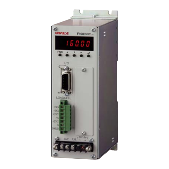
1 OUTLINE 1-3. Appearance Description Chapter ■Front Panel 1. Numerical display 2. Operation button 3. External input/output connector 8. Optional slot 4. Load cell input terminal block 5. SI/F terminal 6. Frame ground terminal 7. DC power input terminal 1. Numerical display Displays indicated values, set values, and error messages. - Page 12 The adaptable plug is Osada-manufactured ETB42-07P or equivalent. (Connector optional type: CN80) 5. SI/F terminal 2-wire serial interface is to connect UNIPULSE peripheral equipment such as printer, remote display or data converter. 6. Frame ground terminal F.G. terminal. Be sure to ground the protective ground terminal to prevent electric shocks and injury by static electricity.
-
Page 13: Connection
2 CONNECTION CONNECTION 2-1. Power Input Connection Chapter Connect the DC power cord. (24V DC (±15%) 10W) Black screw Red screw Within 6mm Terminal block cover Check that no power is applied. Remove the screws (two), and remove the terminal block cover. Remove the screws (two) from the terminal block. -
Page 14: Load Cell Connection
-EXC -EXC * For short-circuiting, (Short-circuit 5 to 6) use the attached SHIELD SHIELD jumper wires. Attention Insert side When installing the terminal block to the F160 body, check its orientation. (Refer to the illustration at the right.) Right side... -
Page 15: Load Cell Signals
2 CONNECTION ■Load Cell Signals +EXC -EXC Chapter -OUT +OUT +SIG -SIG SHIELD (4-wire does not have +S and -S.) ■Connecting Load Cells in Parallel Some industrial applications require several load cells connected in parallel (e.g., tank or flow scales). A summing junction box should be used to facilitate connection and corner correction. ‘n’... -
Page 16: Cable Colors Of Sensors
10V or more, the load cell may generate heat or be damaged. - For connecting a 4-wire load cell to the F160, be sure to connect +EXC and +S, and -EXC and -S. Even if +S and -S are not connected, normal operation will seem to be performed, but the load cell may generate heat or be damaged because excessive voltage is applied. -
Page 17: External Input/Output (Amphenol Connector) Connection
For input The signal input/output circuit inputs signals by short-circuiting and opening the input and COM terminals. Short circuits are made by contact (relay, switch, etc.) or noncontact (transistor, TTL open collector output, etc.). Open F160 Short inside Approx. push toggle... -
Page 18: F Interface Connection
- Connection to the terminal block, make sure that no power is applied. ■Connection of External Devices This is a 2-wire serial interface to connect a UNIPULSE-manufactured printer, external display, etc., which is a nonpolar type, and to which up to three external devices can be connected in parallel. -
Page 19: Setting Procedure
3 SETTING PROCEDURE SETTING PROCEDURE 3-1. Setting Modes Composition Indicated value Indicated value Indicated value display (GROSS) display (NET) display (TARE) Chapter [ FNC ] [ FNC ] Setting Mode 0 Setting Mode 1 Setting Mode 2 [ ▽ ] [ △ ] [ ▽... - Page 20 3 SETTING PROCEDURE Chapter Setting Mode 3 Setting Mode 4 Setting Mode 5 [ ▽ ] [ △ ] [ ▽ ] [ △ ] [ ▽ ] [ △ ] Simple Comparison/ Digital Filter Balance Weight Sequence Mode (P28) (P20) Selection (P33) [ ▽...
- Page 21 3 SETTING PROCEDURE Chapter Setting Mode 6 Setting Mode 7 設定 Ãß›³ºÆ›7 Setting Mode 8 Setting Mode 9 [ ▽ ] [ △ ] [ ▽ ] [ △ ] [ ▽ ] [ △ ] [ ▽ ] [ △ ] External External Tare...
-
Page 22: Setting Procedure
3 SETTING PROCEDURE 3-2. Setting Procedure [FNC] “F0” of setting Mode 0 is displayed. Setting mode selection “F1” of setting Mode 1 “F2” of setting Mode 2 “F9” of setting Mode 9 is displayed. is displayed. is displayed. Chapter Setting item [ △... - Page 23 3 SETTING PROCEDURE Example 1) Setting method by alternatives The F160 handles alternatives by number (numerical value). Since a number is allocated to the set value you select, input that number referring to "9-1.Setting Code List" on page 78. Setting Analog Filter to "0: 2Hz"...
- Page 24 3 SETTING PROCEDURE Example 3) Setting method ① for command execution As for operational commands (setting codes from 80 to 86) in "9-1.Setting Code List" on page 78, operation is executed when each setting is changed from "0" to "1." Executing Digital Zero (setting code 82) From the indicated value display screen, set setting mode 8 by pressing [FNC]→[...
- Page 25 3 SETTING PROCEDURE Executing Equivalent Input Calibration (with the rated output value set at 1.0000mV/V and Balance Weight 25000) From the indicated value display screen, set setting mode 9 by pressing [FNC]→[ Select item number 2 with [△]/[▽]. The item number and set value are displayed. Enable change with [ ], so that the most significant Chapter...
-
Page 26: Calibration
The following two types of calibration are available for the F160. Actual load calibration For example, adjustments are made so that the F160 displays 100.00kg accurately when an actual load (or weight) of 100kg is applied to the load cell (scale part) of the weighing apparatus to which Chapter the F160 is connected. -
Page 27: Calibration Procedure
4-2. Calibration Procedure ■Actual Load Calibration Procedure Perform actual load calibration by the following procedure: Connect the F160 and load cell according to the section Load cell connection "2.CONNECTION" on page 4. Warm-up Release the calibration value lock and the set value lock which locks Lock release calibration. -
Page 28: Equivalent Input Calibration Procedure
(value you want to display) without using an actual load. Rough actual load calibration can be performed without a weight in such a case that the F160 is replaced due to failure or actual load calibration is performed by mistake. -
Page 29: Actual Load Calibration Operation
■Calibration Value Lock Release (Setting code 48) ■Set Value Lock Release (Setting code 49) The F160 has a calibration value (set value) inhibiting (Lock) function which prevents entered calibration value (set value) from unintentional change. This Lock must be released calibrating. -
Page 30: Zero Calibration (Setting Code 90)
4 CALIBRATION ■Zero Calibration (Setting code 90) Adjust the initial zero point. In a set value input state, "0" flashes. Execute with the [ ] button. (Refer to "3-2.Setting Procedure" on page 13.) After execution, it goes back to the gross weight display. When a calibration error is displayed, take measures according to the error message, and do zero calibration again. -
Page 31: Equivalent Input Calibration Operation (Setting Code 92)
4 CALIBRATION 4-4. Equivalent Input Calibration Operation (Setting Code 92) Set the rated output value and reading of the sensor. For the setting method, refer to "Example 4) Setting method ② for command execution" on page 15. Setting range/ 0.3000 to 2.0000 Initial value/ 2.0000 ■Cautions for Equivalent Input Calibration Analog section specification... -
Page 32: Functions
Weight Display ■Gross Weight and Net Weight • Tare Weight The F160 allows weighing by switching the weight between gross weight and net weight. The relationship between the gross weight and net weight is as follows: Gross weight = Net weight + Tare weight... -
Page 33: Preset Tare Weight
5 FUNCTIONS 5-3. Preset Tare Weight This function subtracts a preset tare value from the net weight. This function works when a weight value to be subtracted is input for a tare setting in setting code 09, and tare setting selection in setting code 24 is valid. Preset tare value (Setting code 09) Setting range/ 00000 to 99999 Initial value/ 00000... -
Page 34: Motion Detect (Setting Code 31,32,37)
5 FUNCTIONS 5-6. Motion Detect (Setting Code 31,32,37) Set the parameters to detect that the indicated weight is stable. When the variation width of the weight falls within the set range and that state continues for the set period or more, it is regarded that the weight is stable, and the stability signal turns on. There are stable mode and checker mode in Motion Detection. -
Page 35: Filter In A Stable Condition (Setting Code 36)
Select whether or not it is inserted. Stability is defined by "5-6.Motion Detect (Setting Code 31,32,37)" on page 25. Setting/ 0: Insert (256 times) 1: Not insert Stab OFF or filter is not F160 inserted in stable condition. Analog Digital... -
Page 36: Gravitational Acceleration (Setting Code 47)
5 FUNCTIONS 5-9. Gravitational Acceleration (Setting Code 47) If the scale calibration location and installation location are different, weight errors caused by the regional difference in gravitational acceleration are corrected by this function. If the calibration location and installation location are in the same region, there is no need to set this item. -
Page 37: 5-10.Digital Filter (Setting Code 30)
5 FUNCTIONS 5-10. Digital Filter (Setting Code 30) This function minimizes instability of the weight value through moving average of A/D-converted data. The number of times of moving average can be set as desired up to 1024. The larger the number of times of moving average, the more the weight value becomes stable, but the slower the response becomes. -
Page 38: 5-13.Discharging Control Mode
The discharging control means the control method for discharging raw material from the hopper or tank. F160 enables to discharge accurate quantity with the proper combination of setting the control of Final, Set Point 2, Set Point 1, Compensation and Judging Over, Under, Go and Timer for Comparison Inhibit, Judging. - Page 39 Point The feeding valves and discharge valves should be opened and closed through the PLC or relay sequence according to the control signals from the F160. Chapter Example) In the case when comparing Final, Over/Under, and Near Zero comparison with Net weight.
- Page 40 Chapter F160 (1) The valves of the material tank are opened by the lower limit signal, and raw materials are fed into the weighing tank.
- Page 41 Point The feeding valves and discharge valves should be opened and closed through the PLC or relay sequence according to the control signals from the F160. Example) In the case when comparing Upper/Lower limit comparison and Near Zero comparison with Gross weight, Final and Over/Under with Net weight.
-
Page 42: Discharging Mode (Setting Code 23)
Setting to "External" enables feed and discharge control by external control input. (Refer to "- Feed/ Discharge (Level input)" on page 46.) Setting to "Communication" enables feed and discharge control by the CC-Link interface (option). (Refer to "About RY (PLC→F160) signals" on page .61.) ■Net Weight Sign Inversion in Discharge Weighing (Setting Code 29) When discharging a fixed quantity material from material bin, Net weight becomes negative. -
Page 43: Final/ Set Point2/ Set Point1/ Compensation (Cps)/ Over/ Under (Setting Code 00 To 05)
5 FUNCTIONS ■Final/ Set Point2/ Set Point1/ Compensation (CPS)/ Over/ Under (Setting Code 00 to 05) These settings are for controlling and judging feed/discharge. ex) Simple comparison mode Weight Upper limit Final Over Final - Compensation Under Final - Set Point 2 Final - Set Point 1 Lower limit Chapter... -
Page 44: Upper Limit/ Lower Limit/ Near Zero (Setting Code 06 To 08)
5 FUNCTIONS Setting range and code No. of each set value Set value Setting range Initial value Code No. Final 00000 to 99999 00000 Set point 1 00000 to 99999 00000 Set point 2 00000 to 99999 00000 0000 to 9999 0000 Over 000 to 999... -
Page 45: Upper/Lower Limit Comparison Mode (Setting Code 28)
5 FUNCTIONS ■Upper/Lower Limit Comparison Mode (Setting Code 28) Setting/ 0: Continuous comparison 1: Comparison when the external judgment input is ON ■Comparison Inhibit Time/ Judging Time/ Complete Output Time (Setting Code 10 to 12) Comparison inhibit time/ Judging time These functions inhibit comparison for a fixed period so that control and judgment will not be operated inappropriately due to mechanical vibrations caused by opening and closing of valves. -
Page 46: Complete Output Mode (Setting Code 26)
5 FUNCTIONS ■Complete Output Mode (Setting Code 26) Set the timing to output the complete signal. Parameters that determine the timing are the judging time and stable signal. Setting/ 0: Output by the complete output time after the judging time is up with the SP3 signal ON 1: Output by the complete output time from when the weight value has become stable after the judging time is up with the SP3 signal ON... - Page 47 5 FUNCTIONS Times Actual weighing Error Average count of AFFC. ← Power ON 20.050 +0.050 0.500 20.040 +0.040 0.500 20.070 +0.070 0.500 20.080 +0.080 0.500 4→0 +0.240/4 = 0.060 0.060×2/4 = 0.030 → CPS value 20.020 +0.020 0.530 20.000 0.000 0.530 20.010 +0.010 0.530...
-
Page 48: 5-14.Sequence Control
5 FUNCTIONS 5-14. Sequence Control ■Normal Sequence (With Judgment) Weight Over Final Under Final - Compensation Final - Set Point 2 Final - Set Point 1 Near zero Time Start Chapter Stop Complete Judgment (Over or Go or Under) Comparison inhibit time Judging time Complete output time Hold... - Page 49 5 FUNCTIONS ◆Conditional expressions - Near zero: ON when the weight value ≦ near zero set value. - SP1 output: OFF when the weight value ≧ final set value – set point 1 set value. - SP2 output: OFF when the weight value ≧ final set value – set point 2 set value. - SP3 output: OFF when the weight value ≧...
-
Page 50: Sequence With Adjust Feeding Valid
5 FUNCTIONS ■Sequence with Adjust Feeding Valid Start Stop Complete Judgment (Over or Go) Comparison inhibit time Chapter Judging time Adjust feeding time Complete output time Hold ● Set adjust feeding ON/OFF in the sequence mode of setting code 51 to ON. ●... -
Page 51: Sequence Without Judgment
5 FUNCTIONS ■Sequence without Judgment Start Stop Complete Comparison inhibit time Complete output time ● Over/Under judgment is not made when the setting of the number of judging times of setting Chapter code 15 is 00. ● The complete signal is output at the OFF edge (ON→OFF) of the final (SP3) signal deregarding the setting of the complete output mode of setting code 26. -
Page 52: Relationship Between Auto Zero Times, Judging Times, And Auto Free Fall Compensation
5 FUNCTIONS ■Relationship Between Auto Zero Times, Judging Times, And Auto Free Fall Compensation Start AZ times 3 times Auto zero Complete Judging times 2 times Judgment Average count of auto free 2 times fall compensation Auto free fall compensation ● When the number of auto zero times is set at 01, auto (digital) zero is applied each time weighing starts. -
Page 53: Standard Interfaces
6 STANDARD INTERFACES STANDARD INTERFACES 6-1. External Input/Output (Amphenol Connector) (Setting Code 60 to 66,70 to 74) The external input/output signals are selective. Select necessary signals and set them to each port. However, in the case of redundant settings to input signals, operation is performed as follows: - For the timing of edge operation Functional operation is performed at the edge of any of the input ports assigned with the same signal. -
Page 54: Output (Meanings Of Signals)
6 STANDARD INTERFACES Input assignments Pin No. Port Setting code Initially-specified signal External control input 0 0 (Digital zero reset) External control input 1 1 (Digital zero) External control input 2 2 (Tare subtraction) External control input 3 3 (Tare reset) External control input 4 4 (Hold or Judge) Input allocation... - Page 55 6 STANDARD INTERFACES - Tare subtraction (Edge input) Does tare subtraction at the edge input, and zeros the net weight. - Tare reset (Edge input) Cancels tare subtraction at the edge input. - Hold or judgment (Level input) Valid only in simple comparison mode. If either or both of setting code 27;...
-
Page 56: F 2-Wire Serial Interface
Each display and printer can select the data individually. ●About the auto print command The F160 can output the auto print command to the printer or display connected to the SI/F. The auto print command is output when the complete signal turns ON. Therefore, if the final and over/under comparison is set at “comparison OFF,”... -
Page 57: Option (Setting Code 38)
BCD Parallel Data Output Interface The BCD data output is an interface to extract the indicated value of the F160 as BCD data. This interface is convenient to process controls, totals, records, etc., by connecting the F160 to a computer, process controller, sequencer or the like. -
Page 58: How To Assemble The Connector
7 OPTION (Setting Code 38) ■How to Assemble the Connector Nut M2 (four) Pan-head machine screw Pan-head machine screw M2×10 (long) (two) M2×8 (short) (two) Washer (two) Case (two) Connector Screw (two) Set the connector and screws (two) into the grooves of the case (one side). Cover with the other case, and fit the cases. -
Page 59: Bcd Output Data List
7 OPTION (Setting Code 38) - Connector pin assignments for binary output: FCN-365P032-AU/FCN-360C032-B BCD Data Switch 0 (Response) BCD Data Switch 1 (Response) Minus (Polarity) OVER Output Signal Selection STROBE BCD Data Hold Logic Switch BCD Data Switch 0 BCD Data Switch 1 Currently-selected data can be confirmed by B8 and B9. -
Page 60: Bcd Data Hold
As long as the BCD Data Hold signal is inputted, data can be read reliably, but because the data is not renewed, it may be different from proper data. ■Equivalent Circuit - Output The signal output circuit is operated through an open collector. ●Output pin level F160 Vext Output data Negative Positive Inside... -
Page 61: Signal Timing
7 OPTION (Setting Code 38) CAUTION - Do not apply external voltage to the signal input circuit. - The external element is required to withstand Ic=10mA. - Leakage from the external element is required to be 30μA or below. ■Signal Timing - STAB For example, if the output signal selection is set to "1: Stable,"... -
Page 62: Cc-Link Interface
This document describes the standard specifications of the CC-Link I/F that links a PLC and F160. (For CC-Link Ver.1.10) By using the CC-Link I/F, the F160 can be controlled directly from the PLC, so that wiring can be substantially reduced. -
Page 63: Setting Item (Setting Code 38)
7 OPTION (Setting Code 38) How to connect - Unsheathe individual cable approximately 10mm, insert it in the upper round hole, and clamp it. - At this time, operate the lever with your thumb, while pinching the plug by hand as shown in the illustration on the left-hand side. -
Page 64: Outline Of The Buffer Memory For Communication
F160 (remote device station) is called “R” in the explanation. Since one F160 occupies two stations, station numbers are set as shown below when two or more F160s are connected. The upper column and lower column show the buffer name and buffer address (head), respectively. - Page 65 - Code No. (8 bit binary) (00 to 99) Set a code No. Be aware that the response flag does not turn on to an invalid command. The high byte is ignored. Remote resistor R→M (F160→PLC) Station Buffer Device Description address M→R...
- Page 66 7 OPTION (Setting Code 38) Code list Set value writing and operation instructions (R/W relay OFF) Code No. Setting Range Item (RWw0006) (RWw0004 to 0005) Final 0 to 99999 Set Point 1 0 to 99999 Set Point 2 0 to 99999 Compensation (CPS) 0 to 9999 Over...
- Page 67 7 OPTION (Setting Code 38) Set value writing and operation instructions (R/W relay OFF) continued Code No. Setting Range Item (RWw0006) (RWw0004 to 0005) Balance Weight 0 to 99999 Capacity 0 to 99999 Minimum Scale Division 1 to 100 Net Over 0 to 99999 Gross Over 0 to 99999...
- Page 68 7 OPTION (Setting Code 38) Reading out of set value (R/W relay ON) Code No. Code No. Item Item (RWw0006) (RWw0006) Final Balance Weight Set Point 1 Capacity Set Point 2 Minimum Scale Division Compensation (CPS) Net Over Over Gross Over Under Digital Zero Regulation Value Upper Limit...
- Page 69 7 OPTION (Setting Code 38) Remote output (PLC → F160) Buffer Remote Station Description Class Address Output 0160H RY0000 RY0001 RY0002 Request RY0003 RY0004 RY0005 RY0006 Use for RY0007 communication handshake with RY0008 the host RY0009 RY000A RY000B RY000C RY000D RY000E...
- Page 70 7 OPTION (Setting Code 38) About RY (PLC → F160) signals Signal Meaning Reads or writes set values or performs operational commands at ON Request edge. Turns ON to read set values, and OFF to write set values or perform operational commands.
- Page 71 7 OPTION (Setting Code 38) Relay domain Remote input (F160→PLC) Buffer Remote Station Description Class Address Input 00E0H RX0000 RX0001 RX0002 Response RX0003 R/W (Response) RX0004 RX0005 RX0006 CPU Normal Operation Use for RX0007 communication handshake with RX0008 Decimal Place 0 the host...
-
Page 72: Setting Procedures
7 OPTION (Setting Code 38) About RX (F160 → PLC) signal Signal Meaning It will be “1” when the command request is normally processed, and Response “0” results when the request is turned off. R/W Response Returns the R/W bit status at request-on. - Page 73 7 OPTION (Setting Code 38) Request (RY0002) Response (RX0002) (RY0003) Set value (RWw0004) (RWw0005) Code No. (RWw0006) R/W (response) (RX0003) Code No. (response) (RWr0006) - Operation instruction timing (using special operation instruction bits) Operation instructions can also be given by using the bits from RY0010 to RY0014. The R/W may be either ON or OFF.
-
Page 74: Sample Ladder
7 OPTION (Setting Code 38) ■Sample Ladder “Sample of incrementing the final value from 0 to 99999” CPU........A1SH Station No......1 Master slot ......2 “CC-Link System Master/Local Unit User’s Manual (Detailed Information)” Model: AJ/A1SJ61BT11-U In this sample, the final value is written and read by using the request flag, and two values are compared, and if they correspond, the value is incremented, which is repeated up to “99999.”... - Page 75 [MOV ] [MOV ] Chapter [MOV ] [MOV ] [MOV ] [MOV ] [TO ] *< Remote device F160 occupies 2stations > of PLC start from station 1 M9038 H1201 [MOV ] [TO ] [RST ] M9038 [SET ] [PLS ]...
- Page 76 7 OPTION (Setting Code 38) *Up to here initial setting for communication *<RX PLC read value from F160 > M9036 H0E0 [FROM D200 ] *<RWr PLC read value from F160 > M9036 H2E0 D216 [FROM ] M9036 D200 D400 [WAND ]...
- Page 77 7 OPTION (Setting Code 38) * (M101) *<When response turns ON, > request goes OFF M9038 M101 [WAND H0FFFB D208 ] H160 D208 [TO ] *<To M103 > M103 [SET ] [RST M101 ] *Reading out Final value (M103) *<When response goes OFF, >...
- Page 78 7 OPTION (Setting Code 38) *Initialization M9038 M100 [SET ] [RST M101 ] [RST M102 ] M103 [RST ] M104 [RST ] M106 [RST ] D300 [DMOV ] H160 ] [TO [END ] Chapter...
-
Page 79: Specifications
8 SPECIFICATIONS SPECIFICATIONS 8-1. Specifications ■Analog Section Load cell excitation 10V DC ± 5%, output current within 120mA Remote sensing (Up to four 350Ω load cells can be connected in parallel.) Zero and span Zero adjustment range: 0 to approx. 2mV/V Span adjustment range: 0.3 to 2.0mV/V Signal input range... -
Page 80: Display Section
Final Error, In Operation ( Clock (in an approximately one-second cycles) ■Interface Standard equipment SI/F 2-wire serial interface Chapter This is a simple output serial interface for connection of a UNIPULSE-manufactured printer, external display, etc. Transmission method: Start/stop synchronization Transmission speed: 600bps... -
Page 81: General Performance
8 SPECIFICATIONS ■General Performance Power supply voltage DC24V (±15%) Power consumption 10W (MAX) * At DC24V input Dimensions 67W×185H×120D (mm) (excluding projections) Operating conditions Temperature: Operating temperature range -10 to +40℃ Storage temperature range -20 to +80℃ Humidity: 85%RH or less (non-condensing) Weight Approx. -
Page 82: Dimensions
8 SPECIFICATIONS 8-2. Dimensions ■Mounting Bracket Attachments (Upper/Lower) Chapter Unit: mm Attention Mounting brackets can also be reattached to both sides, but the same screws should be used in doing so. -
Page 83: Mounting Bracket Attachments (Left/Right)
8 SPECIFICATIONS ■Mounting Bracket Attachments (Left/Right) Chapter Unit: mm Attention The same screws should be used in reattaching the mounting brackets. -
Page 84: Equipped With Bcd Parallel Data Output Interface Option
8 SPECIFICATIONS ■Equipped with BCD parallel data output interface option Chapter Unit: mm... -
Page 85: Equipped With Cc-Link Interface Option
8 SPECIFICATIONS ■Equipped with CC-Link interface option Chapter Unit: mm... -
Page 86: Block Diagram
8 SPECIFICATIONS 8-3. Block diagram INPUT Low-pass +SIG AMPLIFIER Fillter -SIG +EXC Excitation Voltage Conversion 24bit -EXC F.G. Referrence Voltage FRAME Watch 32bit Flash 256Kbyte Serial External Lithem Port SRAM Battery 16Kbyte NOV.RAM Port 4096bit Serial Serial Port Port Port 7 segments (6 digits) Control Output... -
Page 87: Supplements
9 SUPPLEMENTS SUPPLEMENTS 9-1. Setting Code List Set value LOCK corresponds to setting code 49. Also, calibration value LOCK corresponds to setting code 48. Set values marked with “ ○” under Set value LOCK and Calibration value LOCK cannot be changed unless these LOCKs are released. Setting to "1"... - Page 88 9 SUPPLEMENTS Mode 2 Calibration Setting Set value Read/write in Page Function Initial value value code LOCK communication number LOCK Over/Under comparison P.35 ○ ◎ Upper/Lower limit comparison P.35 ○ ◎ Near zero comparison P.35 ○ ◎ Feed/discharge control mode P.33 ○...
- Page 89 9 SUPPLEMENTS Mode 5 Calibration Setting Set value Read/write in Page Function Initial value value code LOCK communication number LOCK Simple comparison / P.33 ○ ◎ Sequence mode selection Adjust feeding in sequence mode P.41 ○ ◎ Near zero check in sequence mode P.40 ○...
- Page 90 9 SUPPLEMENTS Operational commands For details of each function, refer to "■Input (Meanings of Signals)" on page 45. For sequence error reset, refer to "■Sequence Error (Setting Code 86)" on page 43. Mode 8 Calibration Setting Set value Read/write in Page Function Initial value value...
-
Page 91: Setting Range Details Of The Set Value
9 SUPPLEMENTS ■Setting Range Details of the Set Value Code Function Setting range Final 00000 to 99999 Set point 1 00000 to 99999 Set point 2 00000 to 99999 Compensation (CPS) 0000 to 9999 Over 000 to 999 Under 000 to 999 Upper limit 00000 to 99999 Lower limit... - Page 92 9 SUPPLEMENTS Code Function Setting range Digital filter 0000 (OFF), 0002 to 1024 [times] Motion detection (period) 0.0 to 9.9 Motion detection (range) 00 to 99 Zero tracking (period) 0.0 to 9.9 Zero tracking (range) 00 to 99 Analog filter 0: 2, 1: 4, 2: 6, 3: 8 [Hz] Filter in a stable condition 0: Insert (256times), 1: Not insert Motion detection mode...
- Page 93 9 SUPPLEMENTS Code Function Setting range Simple comparison / 0: Simple comparison, 1: Sequence mode Sequence mode selection Adjust feeding in sequence mode 0: Invalid, 1: Valid Near zero check in sequence mode 0: Invalid, 1: Valid Weight value check in sequence mode 0: Invalid, 1: Valid Code Function...
-
Page 94: Error List
Output of load cell > and if the output of the load cell is within the span Span adjustment range adjustment range of the F160. Adjust the parameters of motion detection, and check The weight value is not stable and that the "Stable"... - Page 95 9 SUPPLEMENTS About calibration error 2 (cErr2) How to connect a resistor to shift the zero point is as shown below. +EXC +SIG Connect the resistor between +EXC and -SIG. -EXC -SIG Point ・ This table is for 350Ω load cell. ・...
-
Page 96: Weight Alarms
Contents of error Error release Magnitude of signal from the load cell exceeds the F160’s signal input range. Check if the load cell output A/D converter input over is properly within signal input range, or if any of the cables are broken. This error can also occur when the terminal block connections are all open. -
Page 97: Sequence Error
9 SUPPLEMENTS ■Sequence Error Main body display Code Contents of error Error release The stop signal is ON when the weighing start signal is turned ON. The stop signal is ON Turn the stop signal OFF→ON→OFF to resolve the when weighing starts. sequence error, and with the stop signal OFF, input the start signal to start weighing. -
Page 98: Initialization
9 SUPPLEMENTS 9-3. Initialization It is possible to initialize it by the password input of setting mode 9 (setting code 99). 1231: A set value of mode 0 is resumed to an initial value. 1232: The set value memorized in NOVRAM other than Balance Weight, Capacity, Minimum Scale Division, Net Over, Gross Over, Digital Zero Regulation Value, Decimal Place, Gravitational Acceleration, Equivalent input calibration value, Zero Calibration point, and Span Calibration point is resumed to an initial value.
Need help?
Do you have a question about the F160 and is the answer not in the manual?
Questions and answers