
Related Manuals for Furuno SFD-1010


Summary of Contents for Furuno SFD-1010
- Page 1 FLEX FUNCTION DISPLAY SFD-1010/1012 Model (Product Name: SINGLE FUNCTION DISPLAY) www.furuno.com...
- Page 2 ・FURUNO Authorized Distributor/Dealer 9-52 Ashihara-cho, Nishinomiya, 662-8580, JAPAN A : JUL 2022 Printed in Japan All rights reserved. A1 : NOV . 04, 2022 Pub. No. OME-45170-A1 (TASU ) SFD-1010/1012 0 0 0 2 0 0 0 4 4 1 0...
- Page 3 How to discard a used battery Some FURUNO products have a battery(ies). To see if your product has a battery, see the chapter on Maintenance. If a battery is used, tape + and - terminals of the battery before disposal to prevent fire, heat generation caused by short circuit.
- Page 4 SAFETY INSTRUCTIONS Be sure to observe the safety instructions Be sure to observe the following instructions to prevent danger to yourself and others and damage to your property. The levels of danger and damage that may result when displayed contents are ignored or the equipment is used incorrectly are classified and indicated in this manual as shown below.
- Page 5 SAFETY INSTRUCTIONS Safety Instructions on Target Tracking (TT) ⚠ WARNING CAUTION This function is not a substitute for safety About plotting accuracy The plotting accuracy and response speed of monitoring using human vision and human judgment. It is intended to aid the this TT meet the International Maritime monitoring of courses for the safe Organization (IMO) standards.
- Page 6 SAFETY INSTRUCTIONS Safety Instructions on Installation ⚠WARNING CAUTION Do not install the transducer in a Be sure to turn off the power at the place where air bubbles and noise are switchboard before installing the present. equipment. The equipment performance will be Fire or electrical shock can result.
-
Page 7: Table Of Contents
TABLE OF CONTENTS FOREWORD ........................... xi SYSTEM CONFIGURATION ......................xiii EQUIPMENT LIST .......................... xv 1. BASIC OPERATION ......................... 1-1 Controls ........................1-1 Turning Power On/Off ....................1-4 How to Adjust the Brilliance ..................1-5 1.3.1 How to adjust the brilliance of display ............... 1-5 1.3.2 How to adjust the brilliance of panel keys ............ - Page 8 TABLE OF CONTENTS 2. 12 How to Measure the Target Bearing ................. 2-20 2.12.1 How to measure the bearing using Electronic Bearing Lines (EBL) ....2-20 2.12.2 How to change the bearing reference for EBL ..........2-21 2. 13 Target Alert ......................... 2-21 2.13.1 How to set an alert zone .................
- Page 9 TABLE OF CONTENTS 2.25.3 Radar sensor test .................... 2-51 2. 26 Initialization Menu ...................... 2-52 2. 27 Installation Menu ......................2-53 2. 28 Service Menu ......................2-55 2.28.1 Antenna rotation ....................2-55 2.28.2 Operating time....................2-55 2.28.3 Transmission time ................... 2-56 3.
- Page 10 TABLE OF CONTENTS 3.22.2 Range menu ....................3-36 3.22.3 Keypad menu ....................3-37 3.22.4 Language menu ....................3-37 3.22.5 Units menu ...................... 3-37 3.22.6 Calibration menu ..................... 3-38 3.22.7 Demonstration menu ..................3-40 3.22.8 Tests ....................... 3-40 3.22.9 Initialization ..................... 3-42 4.
- Page 11 TABLE OF CONTENTS 4. 10 SYSTEM Menu ......................4-44 4. 11 Demo ......................... 4-46 4. 12 Test Menus ........................ 4-47 4. 13 Reset Menu ........................ 4-50 5. INSTALLATION ........................5-1 5. 1 Mounting ........................5-1 5.1.1 Place suitable for mounting ................. 5-1 5.1.2 Desktop mount ....................
- Page 12 TABLE OF CONTENTS TABLE OF CONTENTS 6.3.1 General problems ....................6-2 6.3.2 Radar problems....................6-3 6.3.3 Fish finder problems .................... 6-3 6. 4 Alert List ........................6-4 6.4.1 Radar ........................6-4 6.4.2 Fish finder ......................6-4 6.4.3 Multi beam sonar ....................6-4 APPX.1 MENU TREES ......................
-
Page 13: Foreword
FOREWORD Thank you for purchasing FURUNO equipment. Since its foundation in 1948, FURUNO Electric Company has been manufacturing and selling a variety of marine electronics equipment and has been enjoying a high reputation for performance, quality and reliability from users around the world. This equipment is designed and manufactured under a strict quality control system to ensure its performance and durability. - Page 14 URL if you need source codes: https://www.furuno.co.jp/contact/cnt_oss01.html. Program no. System1: 1950222-x.x.x System2: 1950223- x.x.x Application: 1950228- x.x.x x:Minor change of software CE declaration With regards to CE declarations, please refer to our website (www.furuno.com), for further information about RoHS conformity declarations.
-
Page 15: System Configuration
*: One unit of radar sensor, fish finder sensor and multi beam sonar can be connected at the same time. *: Two units of SFD-1010/1012 can be connected to the same network as the maximum. Note: When the DFF-3D is connected, turn on the power of DFF-3D, then turn on the power of SFD-1010/1012. - Page 16 SYSTEM CONFIGURATION ○ Configuration with two display units (1) The following connections enable the radar operations from both SFDs. When both a fish finder and radar are connected, both SFDs can operate fish finder or radar. Using the Auto IP function, IP address is assigned without causing ...
-
Page 17: Equipment List
EQUIPMENT LIST Standard supply SFD-1010 Name Type Code No. Qty. Remarks Display Unit SFD-1010 000-038-078 Spare Parts SP03-17801 001-600-090 Accessories CP19-02801 001-600-100 Installation Materials FP02-05700 000-011-976 SFD-1012 Name Type Code No. Qty. Remarks Display Unit SFD-1012 000-038-080 Spare Parts SP03-17801... - Page 18 MOD-Z072-100+(10m) 000-167-177-11 Cross pair, 10m 19S1181 RU-3423 000-030-443 000-013-484 For AC100V 000-013-485 For AC110V Rectifier PR-62 000-013-486 For AC220V 000-013-487 For AC230V RU-1746B-2 000-030-443 Ethernet Hub HUB-101 000-011-762 OP19-27 000-199-172-10 For SFD-1010 Flush Mount Kit OP19-28 000-199-173-10 For SFD-1012 xviii...
-
Page 19: Basic Operation
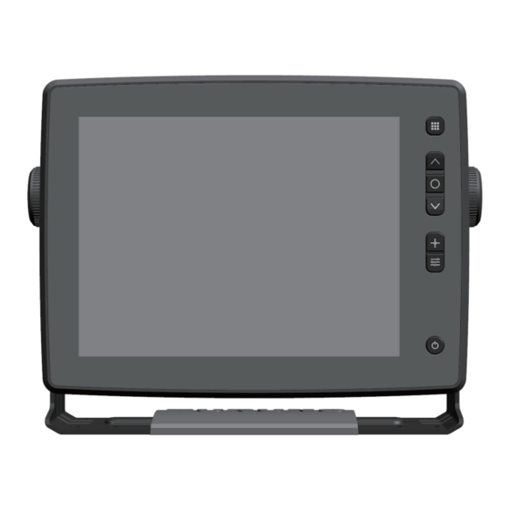
1. BASIC OPERATION Controls This equipment is operated with a touchscreen and hardware keys. Description of keys When using When using When using multi radar fish finder beam sonar MENU/ESC ① Move cursor, change range ② ENTER / Switch ENTER ③... - Page 20 1. BASIC OPERATION When operating radar: TLL Outputs TLL. ⑤ • When operating fish finder: Displays fixed mark at selected location. • Fixed mark, TLL Outputs TLL. • When using radar: Opens/closes the [PICTURE CONTROL] menu. ⑥ • [PICTURE CONTROL] menu Adjusts the gain, sea clutter reduction level and •...
- Page 21 1. BASIC OPERATION Touch control description A finger or two are used for touch control. The basic operations are as shown below. Touch control Function Lightly touch the screen with your Select a menu item. finger and then Select a target object or a point on the remove your finger screen to display the [POPUP] menu.
-
Page 22: Turning Power On/Off
1. BASIC OPERATION Touch control: Short press the POWER/BRILLIANCE key to open the [BRILLIANCE] menu. Tap the [LOCK TOUCH SCREEN] menu. Tap [ON]. All screen-based controls are disabled. How to unlock the touch screen: Short press the POWER/BRILLIANCE key to open the [BRILLIANCE] menu. Select the [LOCK TOUCH SCREEN] menu with the arrow keys, then press the ENTER key. -
Page 23: How To Adjust The Brilliance
1. BASIC OPERATION How to turn off the power with a long press of the POWER/BRILLIANCE key Press and hold the POWER/BRILLIANCE key for two seconds. The time left before the power off is shown on the screen. Press and hold the POWER/BRILLIANCE key for another three seconds to turn off the equipment. -
Page 24: Description Of Menu Setting Window
1. BASIC OPERATION Key control: Press the POWER/BRILLIANCE key. Select the [KEY BRILLIANCE] menu with the arrow keys, then press the ENTER key. Press the arrow keys for adjustment. Press the ENTER key to confirm. Press the MENU/ESC key to close [MENU]. When using radar When using fish finder/ Multi beam sonar Description of Menu Setting Window... -
Page 25: Toggle-Type Window
1. BASIC OPERATION 1.4.3 Toggle-type window Select an option by tapping the display or key control. When the settings are only [On] or [Off], the setting window is referred as toggle- type window. Fish finder/ Multi beam sonar Radar 1.4.4 Confirmation-type window Select an option by tapping the display or key control. -
Page 26: Display Indications
1. BASIC OPERATION Display Indications 1.5.1 Radar display The display screen provides various alphanumeric indications which show operational status and data input from external equipment. Whenever a change occurs, the display indications change accordingly. Name Description Touch control ⓐ Range box Changes the display range. - Page 27 1. BASIC OPERATION Name Description Touch control Displays the time to go to a destination (factory ⓙ Waypoint information box Disabled default setting), bearing and range. ⓚ Target data box Displays target information. Disabled ⓛ Trail time box Displays the set trail time. Disabled Activates/deactivates the EBL1 and EBL2.
-
Page 28: Fish Finder Display
1. BASIC OPERATION 1.5.2 Fish finder display Information showing various setting status is displayed on the screen. If any changes are made to these settings, the contents displayed in the information box change accordingly. Name Description Touch control Range box Displays range setting. - Page 29 1. BASIC OPERATION Name Description Touch control Enabled InstantAccess Displays the InstantAccess Bar menu. ⓟ Displays echo strength with width and color Disabled A-Scope ⓠ brightness. 1-11...
-
Page 30: Multi Beam Sonar Display
1. BASIC OPERATION 1.5.3 Multi beam sonar display Information showing various setting status is displayed on the screen. If any changes are made to these settings, the contents displayed in the information box change accordingly. Multi beam fish finder Name Description Touch control ⓐ... - Page 31 CHAPTER 1 BASIC OPERATION 1. BASIC OPERATION Side scan Name Description Touch control Enabled ⓐ InstantAccess Depth scale Measures the water depth. Disabled ⓑ Displays the settings of the items set in [DATA] Data box Disabled ⓒ → [DATA DISPLAY]. ⓓ...
- Page 32 1. BASIC OPERATION Cross section display Name Description Touch control Enabled ⓐ InstantAccess Depth scale Measures the water depth. Disabled ⓑ Displays the settings of the items set in [DATA] Data box Disabled ⓒ → [DATA DISPLAY]. ⓓ Gain Displays the gain status. Disabled Depth Displays depth.
- Page 33 1. BASIC OPERATION 3D history display Name Description Touch control Enabled ⓐ InstantAccess Displays the setting of an item set in [DATA] → Data box Disabled ⓑ [DATA DISPLAY]. ⓒ Gain Displays the gain status. Disabled Depth Displays depth. Disabled ⓓ...
- Page 34 1. BASIC OPERATION Name Description Touch control Bottom depth/ Displays the legacy of bottom depth and Disabled ⓙ gradation gradation. Current Displays the water current. Disabled ⓚ ⓛ Displays the net. Disabled School of fish depth/ Displays the legacy of fish school depth and ⓜ...
-
Page 35: Radar
2. RADAR Basic Operation of Radar 2.1.1 Transmission/stand-by When the magnetron is warmed, the indication “ST-BY” appears on the display, telling you that the radar is ready for transmission. To start the transmission, tap [ST-BY] in the [ST-BY]/ [TX] box at the upper left corner of the screen. -
Page 36: Working Indicator
2. RADAR 2.1.2 Working indicator The working indicator shows the working status of the radar sensor (working normally or rotation stopped, etc.). When the radar is working normally, the working indicator rotates clockwise steadily. However, when the radar rotation is stopped, the working indicator stops rotating. The working indicator cannot be switched on and off. -
Page 37: Screen Display Examples, Instantaccess
2. RADAR 2.1.3 Screen display examples, InstantAccess Bar items You can set the following contents from the InstantAccess Bar. Item Content Erases the heading line temporarily. RING Adjusts range ring brilliance. OFF CENTER Shifts own ship position to selected location. TGT ALARM 1 Sets the no.1 acquisition zone. -
Page 38: Overview Of Menu Operations
2. RADAR 2.1.4 Overview of menu operations 17 menus are available. This section describes basic menu items. To select a menu, tap a menu or move the cursor onto the menu you want to select with the arrow keys, then press the ENTER key. Description of menus Menu Description... -
Page 39: Tuning
2. RADAR 2.1.5 Tuning After radar transmission is started, tune the receiver. This radar can tune the receiver automatically or manually. The tuning mode is set to [Auto] as a factory default. Tuning mode - Manual Tuning mode - Auto How to change to manual tuning and tune the receiver Take the following steps to manually tune the receiver. -
Page 40: Display Modes
2. RADAR Display Modes This radar has three display modes available. All modes except head-up require a heading signal. HEAD-UP: Heading line is always oriented toward the top of the screen. NORTH-UP: Bearing scale is stabilized with reference to north. COURSE-UP: The heading line is directed toward the desired direction (such as destination or port) at the moment course up is selected. -
Page 41: Description Of Display Modes
2. RADAR 2.2.2 Description of display modes HEAD-UP A mode in which the heading line is always indicated toward the top of the screen. Since targets are shown as if they are seen from a bridge, this mode is suitable for ship handling in narrow channels and crowded sea areas. -
Page 42: How To Adjust The Gain
2. RADAR How to Adjust the Gain To properly display a target, the gain needs to be adjusted according to signal strength. You can select [Manual] or [Auto] and also adjust the gain strength from the [ADJUST] menu. When adjusting the gain, increase the gain until just before background noise appears on the display. - Page 43 2. RADAR Manual adjustment Touch control: Press the [ADJUST] key to open the [ADJUST] menu. Tap the [Sea] menu to open the [Manual]/[Auto] selection box. Tap [Manual]. Drag the slider bar of the [Sea] menu or tap [+] or [-] to adjust the sea clutter level. Tap [x] on the title bar to close the [ADJUST] menu.
- Page 44 2. RADAR Tap either [Advanced]/[Coastal]. Tap [x] on the title bar to close the [ADJUST] menu. Key control: Press the MENU key to display menu. Select [ECHO ADJ] menu with the arrow keys, then press the ENTER key. Select [Auto SEA] menu with the arrow keys, then press the ENTER key. [Advanced]/[Coastal] selection box appears.
-
Page 45: How To Reduce Rain Clutter
2. RADAR How to Reduce Rain Clutter Radio waves transmitted from the antenna and reflected by rain or snow appear in the picture on the screen. Use the rain clutter reduction function when rain clutter masks the targets. The rain clutter reduction level is adjusted in the similar manner as that for the sea clutter reduction. -
Page 46: Cursor
2. RADAR Cursor The cursor can be used for measuring the distance and bearing between own ship and targets as well as for checking the latitude and longitude position of targets. Drag the + cursor on the target to display the distance/bearing and latitude/longitude information in the + cursor data box at the top right of the screen. -
Page 47: Heading Line And North Marker
2. RADAR Heading Line and North Marker 2.8.1 Heading line The heading line shows the own ship’s heading. In the HEAD-UP mode, the heading line appears right above own ship (0°). In the NORTH-UP and the COURSE-UP modes, the heading line moves according to own ship's movement. 2.8.2 How to adjust the heading line A small but conspicuous target dead ahead may appear on the heading line (zero... -
Page 48: How To Erase The Heading Line Temporarily
2. RADAR 2. Turn own ship’s heading to the center of the target. 3. Press the MENU key to display the menu. 4. Select [SCANNER SETUP]. 5. Select [Heading Alignment]. 6. Tap [+]/[-] key or drag the slider bar so that the target appears at the top of display. -
Page 49: Interference Rejection
2. RADAR Interference Rejection When radars using the same frequency band (X band: 9 GHz) are in the vicinity of the own ship, interference may appear on the screen. It is seen in irregular patterns, as several dotted lines extending from the center to the edge of the picture on the screen. -
Page 50: Noise Rejection
2. RADAR Select the [ECHO ADJUST] menu with the arrow keys, then press the ENTER key. Select [Int Rejector] with the arrow keys, then press the ENTER key. The [Off]/[On] selection box appears. Select [On] with the arrow keys, then press the ENTER key. Press the MENU/ESC key to close [MENU]. -
Page 51: How To Measure The Range To A Target
CHAPTER 2 RADAR 2. RADAR Using the [ECHO ADJUST] menu for interference rejection Touch control: Press the MENU/ESC key to open [MENU]. Tap the [ECHO ADJUST] menu. Tap the [Noise Rejector] menu. The [Off]/[On] selection box appears. Tap [On]. Tap [x] on the title bar to close [MENU]. Key control: Press the MENU/ESC key to open [MENU]. - Page 52 2. RADAR Tap [Rings Brill]. The [Off]/[1]/[2]/[3]/[4] selection box appears. Tap [Off], [1], [2], [3] or [4]. Tap [x] on the title bar to close [MENU]. Key control: Press the MENU/ESC key to open [MENU]. Select [BRILL/COLOR] with the arrow keys, then press the ENTER key. Select [Rings Brill] with the arrow keys, then press the ENTER key.
-
Page 53: How To Measure The Range With The Variable Range Marker (Vrm)
2. RADAR 2.11.2 How to measure the range with the Variable Range Marker (VRM) There are two VRMs, VRM1 and VRM2, which appear as dashed rings on the screen so that you can distinguish them from the fixed range rings. VRM1 and VRM2 can be distinguished from each other by the different lengths of their dashes. -
Page 54: How To Measure The Target Bearing
2. RADAR Select [NM], [km], [SM], [KYD] or [NM&YD] with the arrow keys, then press the ENTER key. Press the MENU/ESC key to close [MENU]. 2.12 How to Measure the Target Bearing The Electronic Bearing Lines (EBLs) are used to take bearings of targets. There are two EBLs, EBL1 and EBL2. -
Page 55: How To Change The Bearing Reference For Ebl
CHAPTER 2 RADAR 2. RADAR 2.12.2 How to change the bearing reference for EBL “R” is indicated in the EBL box if the EBL readout is relative to own ship’s heading, and “T” is indicated if it is referenced to the north (true bearing). The indication can be switched between relative bearing and true bearing when the display mode is HEAD-UP. -
Page 56: How To Show, Hide The Alert Zone
2. RADAR Tap [Enter Start Position]. The indication changes from [Enter Start Position] to [Enter End Position]. Tap the ending point for the alert zone, and the cursor moves to that point. Tap [Enter End Position] so that the fan-shaped zone is set as a target alert zone. Note 1: To cancel the alert zone setting, tap [Cancel]. -
Page 57: How To Turn The Target Alert Alarm On/Off
2. RADAR Key control: Press the MENU/ESC key to open [MENU]. Select [ALERT SETTINGS] with the arrow keys, then press the ENTER key. Select [Target Alarm 1] or [Target Alarm 2] with the arrow keys, then press the ENTER key. The [In]/[Out] selection box appears. -
Page 58: Watchman
CHAPTER 2 RADAR 2. RADAR Tap [Panel Buzzer] or [External Buzzer]. The [On]/[Off] selection box appears. Tap [On] or [Off]. Tap [x] on the title bar to close [MENU]. Key control: Press the MENU/ESC key to open [MENU]. Select [ALERT SETTINGS] with the arrow keys, then press the ENTER key. Select [Panel Buzzer] or [External Buzzer] with the arrow keys, then press the ENTER key. -
Page 59: Off-Center (Shifting The Screen Center)
2. RADAR Key control: Press the MENU/ESC key to open [MENU]. Select [ALERT SETTINGS] with the arrow keys, then press the ENTER key. Select [Watchman] with the arrow keys, then press the ENTER key. The [Off]/[5min]/[10min]/[20min] selection box appears. Select [Off]/[5min]/[10min]/[20min] with the arrow keys, then press the ENTER key. Press the MENU/ESC key to close [MENU]. -
Page 60: Zoom
2. RADAR 2.17 Zoom The zoom function can enlarge a part of the radar picture as large as twice the normal viewing size. 2.17.1 How to change a zoom mode You can select a zoom mode from three types, [Relative], [True] and [Target]. Relative: The set zoom cursor is fixed to the constant range and bearing from own ship. -
Page 61: How To Use The Zoom Function
2. RADAR 2.17.2 How to use the zoom function There are two ways to use the zoom function: from the InstantAccess Bar and from the menu. Using the InstantAccess Tap [▶] on the left side of the screen to open the InstantAccess Bar, then tap [ZOOM]. -
Page 62: Echo Trail
2. RADAR 2.18 Echo Trail Echo trails show the trails of other ships with a color different from the current echo color, which is useful for monitoring ship movement. Relative trails and true trails are available in the echo trail mode. True echo trails require heading and speed signals and position information. -
Page 63: How To Change The Trail Mode
2. RADAR Select [Trail Erase] with the arrow keys, then press the ENTER key. The [YES]/[NO] selection box appears. Select [YES] or [NO] with the arrow keys, then press the ENTER key. Press the MENU/ESC key to close [MENU]. 2.18.3 How to change the trail mode [True] trails and [Relative] trails are available in the echo trail mode. -
Page 64: How To Change The Trail Gradation
2. RADAR 2.18.4 How to change the trail gradation The target trails can be displayed in a single tone of the same density or with gradual shading that fades with time. Touch control: Press the MENU/ESC key to open [MENU]. Tap [TRAILS]. -
Page 65: How To Change The Trail Color
2. RADAR 2.18.5 How to change the trail color The trail color can be selected among blue, yellow and green. Touch control: Press the MENU/ESC key to open [MENU]. Tap [TRAILS]. Tap [Color]. The [Blue]/[Yellow]/[Green] selection box appears. Tap [Blue], [Yellow] or [Green]. Tap [x] on the title bar to close [MENU]. -
Page 66: Assigning Functions To The Function Keys
2. RADAR Select [1], [2] or [3] with the arrow keys, then press the ENTER key. Press the MENU/ESC key to close [MENU]. 2.19 Assigning Functions to the Function Keys Functions in the menu can be assigned to the function keys [F1] and [F2]. The function assigned to F1 button appears at the second from the bottom of the InstantAccess Bar and the function assigned to F2 button appears at its bottom. -
Page 67: Echo Averaging
CHAPTER 2 RADAR CHAPTER 2 RADAR 2. RADAR 2.20 Echo Averaging The echo averaging function allows you to change the brilliance of targets in sea clutter, which makes it easier to discriminate small targets from sea clutter. Note 1: Do not use the echo averaging function under heavy pitching and rolling; loss of targets can result. -
Page 68: How To Set The Display Curve
2. RADAR Select [Echo Average] with the arrow keys, then press the ENTER key. The [On]/[Off] selection box appears. Select [On] or [Off] with the arrow keys, then press the ENTER key. Press the MENU/ESC key to close [MENU]. 2.21 How to Set the Display Curve The optimum display curves changes with sea conditions and desired targets. -
Page 69: Alert List
2. RADAR 2.22 Alert List Currently active alerts are listed on the alert list. The list can be displayed as shown below. Note: Unacknowledged alerts are not shown. Touch control: Press the MENU/ESC key to open [MENU]. Tap [ALERT LIST]. The currently active alerts are shown on the right side. -
Page 70: User Setting
2. RADAR Touch control: Press the MENU/ESC key to open [MENU]. Tap [BRILL/COLOR]. Tap [Display Color]. The [Day]/[Dusk]/[Night]/[Custom] selection box appears. Tap [Day], [Dusk], [Night] or [Custom]. Tap [x] on the title bar to close [MENU]. Key control: Press the MENU/ESC key to open [MENU]. Select [BRILL/COLOR] with the arrow keys, then press the ENTER key. - Page 71 CHAPTER 2 RADAR 2. RADAR Press the MENU/ESC key to close [MENU]. How to change the background color Touch control: Press the MENU/ESC key to open [MENU]. Tap [BRILL/COLOR]. Tap [Background Color]. The [Black]/[Navy]/[Blue]/[White] selection box appears. Tap [Black], [Navy], [Blue] or [White]. Tap [x] on the title bar to close [MENU].
-
Page 72: How To Change The Brilliance Of Marks, Heading Line And Characters
2. RADAR Tap [Character Color]. The [Green]/[Red]/[White] selection box appears. Tap [Green], [Red] or [White]. Tap [x] on the title bar to close [MENU]. Key control: Press the MENU/ESC key to open [MENU]. Select [BRILL/COLOR] with the arrow keys, then press the ENTER key. Select [Character Color] with the arrow keys, then press the ENTER key. -
Page 73: Tt Operation
2. RADAR 2.24 TT Operation The TT (Target Tracking) function manually or automatically acquires and tracks targets displayed on the screen. Once a target is acquired, it is automatically tracked within the range of 0 to 16 NM. A maximum of 30 targets can be acquired and tracked. The acquisition range is 0.1 NM to 16 NM. -
Page 74: How To Change The Tt Symbol (Acquisition Symbol) Color
2. RADAR 2.24.2 How to change the TT symbol (acquisition symbol) color You can select the acquisition symbol color among green, red, blue, white and black. Touch control: Press the MENU/ESC key to open [MENU]. Tap [TT]. Tap [TT Color]. The [Green]/[Red]/[Blue]/ [White]/[Black] selection box appears. -
Page 75: How To Acquire And Track Targets
2. RADAR 2.24.3 How to acquire and track targets This equipment can manually or automatically acquire and track targets. How to manually acquire targets Tap the target to acquire, and the cursor appears. Tap the [ACQUIRE] button displayed below the data box. Note: If any of the following conditions is not met, the manual acquisition is not activated and error sound beeps. -
Page 76: How To Cancel The Tracking
CHAPTER 2 RADAR 2. RADAR 2.24.4 How to cancel the tracking How to cancel tracking of individual targets Tap the acquisition symbol of the target for which you want to cancel tracking, and the cursor appears on the target. Tap [CANCEL] shown on the right side of the screen. 2.24.5 Lost target Targets cannot be tracked if echoes from the tracking target disappear. -
Page 77: Tt All Cancel
2 RADAR 2. RADAR Select [Yes] or [No] with the arrow keys, then press the ENTER key. Press the MENU/ESC key to close [MENU]. 2.24.6 TT All Cancel Take the following steps to cancel all TT and erase the symbols. Touch control: Press the MENU/ESC key to open [MENU]. -
Page 78: How To Display The Tt Vector
2. RADAR 2.24.7 How to display the TT vector What is a vector? A vector is a line extending from the center of a tracked target, and it shows the speed and course of the target. The vector tip shows an estimated position of the target after the selected vector time elapses. -
Page 79: How To Display Tt Data
2. RADAR 2.24.8 How to display TT data Data on tracked targets (bearing, course, range, speed, CPA, TCPA) are displayed in the data box on the right side of the screen. Set the [TT DISPLAY] menu in the [TT] menu to [On] to show the data. Tap a TT target whose information you want to view. - Page 80 2. RADAR Select [Past Positions] with the arrow keys, then press the ENTER key. The [Off]/[5]/[10] selection box appears. Select [Off], [5] or [10] with the arrow keys, then press the ENTER key. Press the MENU/ESC key to close [MENU]. How to display past position points and select the plotting interval Touch control: Press the MENU/ESC key to open [MENU].
-
Page 81: How To Set A Collision Alert (Cpa/Tcpa Alert)
2. RADAR 2.24.10 How to set a collision alert (CPA/TCPA alert) To avoid collision with other ships, preset a threshold for CPA (Closest Point of Approach to own ship by other ships) and TCPA (Time to Closest Point of Approach). If both the CPA and TCPA of a tracking target becomes smaller than these two thresholds, the target is recognized as a dangerous target (lit in red) and an alert message appears simultaneously in the “ALERT LIST”... -
Page 82: Proximity Alert
2. RADAR Tap [30 s], [1 min], [2 min], [3 min], [4 min], [5 min], [6 min] or [12 min]. Tap [x] on the title bar to close [MENU]. Key control: Press the MENU/ESC key to open [MENU]. Select [ALERT SETTINGS] with the arrow keys, then press the ENTER key. Select [TCPA] with the arrow keys, then press the ENTER key. -
Page 83: Test Menus
2. RADAR Tap [Off], [0.5NM], [1NM], [2NM], [3NM], [5NM], [6NM], [12NM] or [24NM] with the arrow keys, then press the ENTER key. Press the MENU/ESC key to close [MENU]. 2.25 Test Menus 2.25.1 Self-diagnostic test [Self Test] checks the connection state, the data from external equipment, and the key pad for proper operation. -
Page 84: Lcd Test
To quit the test, press the MENU/ESC key three times. Note: When connecting multiple units of SFD-1010/1012 on the same network and the test is started on one unit, displayed contents on other units may be interrupted. -
Page 85: Radar Sensor Test
2. RADAR -> -> -> -> -> -> -> -> -> -> -> -> To quit the test, press the MENU/ESC key. 2.25.3 Radar sensor test The [Radar Sensor Test] checks whether radar sensors are properly connected or not. Touch control: Press the MENU/ESC key to open [MENU]. -
Page 86: Initialization Menu
2. RADAR 2.26 Initialization Menu This menu initializes the selected memory. How to initialize the sensor memory Take the following steps to initialize the sensor memory. Touch control: Press the MENU/ESC key to open [MENU]. Tap [RESET]. Tap [Reset Sensor]. A popup message appears. -
Page 87: Installation Menu
2. RADAR 2.27 Installation Menu The [INSTALLATION] menu provides the following items. [Wheel Drive]: Scrolling direction of the mouse wheel can be selected from [Normal] or [Reverse]. [Language]: Select the display language to use. [Orientation Setting]: Change the screen orientation, between landscape and portrait. Touch control: Press the MENU/ESC key to open [MENU]. - Page 88 2. RADAR Key control: Press the MENU/ESC key to open [MENU]. Select [INSTALLATION] menu with the arrow keys, then press the ENTER key. Select [Orientation Switching] with the arrow keys, then press the ENTER key. A popup message appears. Select [YES] or [NO] with the arrow keys, then press the ENTER key. Selecting “YES”...
-
Page 89: Service Menu
2. RADAR 2.28 Service Menu To show the [SERVICE] menu, press the TLL key five times while pressing the MENU/ESC key. 2.28.1 Antenna rotation Take the following steps to start or stop antenna rotation. Touch control: Press the MENU/ESC key to open [MENU]. Tap [SERVICE]. -
Page 90: Transmission Time
2. RADAR Key control: Press the MENU/ESC key to open [MENU]. Select [SERVICE] with the arrow keys, then press the ENTER key. Select [OPERATING TIME] with the arrow keys, then press the ENTER key. The cursor moves to the slider bar on the right side of the menu. For the service technician: Adjust the operating time with the arrow keys. - Page 91 2. RADAR Press the MENU/ESC key to close [MENU]. Note: After setting the total TX time, a popup asks if you are sure to change the setting. Select [YES] to change the setting, or [NO] to escape and keep the previous setting.
- Page 92 2. RADAR This page is intentionally left blank. 2-58...
-
Page 93: Fish Finder
3. FISH FINDER Basic Operation of Fish Finder 3.1.1 Transmission/stand-by To start transmission, open the [MENU], select [SOUNDER], then set [Transmit] to [On]. To enter the stand-by mode, set [Transmit] to [Off]. [Off] in a similar manner. Transmission On state Transmission Off state... -
Page 94: Screen Display Examples, Instantaccess
3. FISH FINDER 3.1.2 Screen display examples, InstantAccess Bar items The contents of InstantAccess Bar can be set at [IA BAR] in [MENU]. -
Page 95: Overview Of Menu Operations
3. FISH FINDER Items Contents Function 1 to Selected menu on [MENU] - [IA BAR] menu appear. Function 8 Each preset menu (Function 1 to Function 8) can be selected Preset 1 to Preset 3 on [MENU] – [IA BAR] menu. 3.1.3 Overview of menu operations This equipment has six menus related to fish finder operations: [SOUNDER],... -
Page 96: Display Modes
3. FISH FINDER Display Modes There are seven fish finder display modes in total. Select a mode according to your purpose. 3.2.1 How to Select a display mode Touch control: Press the Popup menu key to open the [Popup] menu. Tap [Mode]. -
Page 97: Description Of Display Modes
3. FISH FINDER 3.2.2 Description of display modes Single frequency display Low frequency or high frequency picture appears on the entire screen. Low frequency High frequency The lower the frequency of the ultrasonic waves frequency emitted into the sea, the wider the search range and the deeper a school of fish can be detected. - Page 98 3. FISH FINDER Zoom displays (low frequency / high frequency) This mode expands a part of the single frequency picture (low frequency or high frequency). There are two types of enlarged displays, “bottom lock display” and “bottom zoom”. Bottom lock display This mode provides a “low frequency”...
-
Page 99: How To Select A Range
3. FISH FINDER Bottom zoom This mode provides a “low frequency” picture on the right half of the screen and a picture of the bottom is expanded onto the left half of the screen. This is useful for detailed observation of bottom contour and bottom material changes. When the bottom echo goes beyond the boundary defined by the zoom range marker, the display is automatically shifted to keep the bottom echo within the lower part of the zoom range. -
Page 100: Adjusting The Gain
3. FISH FINDER Auto By selecting [On] in [Range Auto], the range automatically changes to display the sea bottom always within the designated range on the screen. (Note that the shift function is inoperative in the auto mode.) [Auto] is shown at the top of the screen. Manual By selecting [Off] in [Range Auto], the range can be selected from the eight ranges. -
Page 101: How To Set Up The Manual Mode
3. FISH FINDER [Cruising] This mode clearly displays stronger echoes and suppresses weak echoes so it is suitable for cruising to a fishing ground. [AC] is shown at the top of the screen. It is useful if you select [Cruising] for cruising to a fishing ground and change it to [Fishing] when you arrive there. -
Page 102: How To Measure The Time And Depth To Objects
3. FISH FINDER Key control: Press the Popup menu key to open the [Popup] menu. Select [Gain Auto] with the arrow keys, then press the ENTER key. Select [Off] with the arrow keys, then press the ENTER key. Select [Gain HF] or [Gain LF] with the arrow keys, then press the ENTER key. Set the gain adjustment level with the arrow keys, then press the ENTER key. -
Page 103: Shifting The Display Range (Shift Function)
3. FISH FINDER Shifting the Display Range (Shift Function) The current display range can be shifted up and down to see deeper or shallower places. This up and down shifting movement is called the “shift”. You can shift the display range up or down to see deep or shallow locations. -
Page 104: Picture Advance Speed
3. FISH FINDER Picture Advance Speed The same school of fish or the same bottom appears differently on the screen according to the picture advance speed. The fast advance speed expands the pictures horizontally and a slow advance speed contracts them horizontally. Use a fast advance speed to precisely observe a rugged bottom. -
Page 105: How To Reduce Interference
3. FISH FINDER How to Reduce Interference The noise induced by own ship’s electrical equipment and the periodic interference from other ship’s fish finder can be reduced. Turn off the interference rejection function when there is little interference so that weak echoes are not missed. -
Page 106: How To Erase Weak Echoes
3. FISH FINDER Key control: Press the MENU/ESC key to open [MENU]. Select [SOUNDER] with the arrow keys, then press the ENTER key. Select [Clutter] with the arrow keys, then press the ENTER key. Set the clutter level with the arrow keys, then press the ENTER key. Press the MENU/ESC key to close [MENU]. -
Page 107: How To Adjust The Window Size
3. FISH FINDER Peak: Shows an amplitude picture for each transmission plus the maximum amplitude picture for last five seconds in dots. Tap [x] on the title bar to close [MENU]. Key control: Press the MENU/ESC key to open [MENU]. Select [DISPLAY] with the arrow keys, then press the ENTER key. -
Page 108: Screen Display Colors
3. FISH FINDER Key control: Press the MENU/ESC key to open [MENU]. Select [DISPLAY] with the arrow keys, then press the ENTER key. Select [Window Size] with the arrow keys, then press the ENTER key. Set the window size with the arrow keys, then press the ENTER key. Press the MENU/ESC key to close [MENU]. -
Page 109: Header
3. FISH FINDER Key control: Press the MENU/ESC key to open [MENU]. Select [DISPLAY] with the arrow keys, then press the ENTER key. Select [Palette] with the arrow keys, then press the ENTER key. The [White]/[Blue]/[Black]/[Mono]/[Night] selection box appears. Select [White], [Blue], [Black], [Mono] or [Night] with the arrow keys, then press the ENTER key. -
Page 110: Header Scale
3. FISH FINDER 3.14.2 Header scale Select the method to show the header scale (time mark or range mark). When the header scale is shown as a time marker, orange and white bar appear for 30 seconds each. When the header scale is shown as a range marker, green and white bars appear for 0.3 NM each. -
Page 111: Accu-Fish
3. FISH FINDER 3.15 ACCU-FISH ACCU-FISH , which requires a DFF series transducer or BBDS1, measures the size and depth of individual fish and marks them with the ACCU-FISH icon. ACCU-FISH operates both in the high frequency and low frequency modes. ... -
Page 112: Calibration Of Fish Size Values
3. FISH FINDER Key control: Press the MENU/ESC key to open [MENU]. Select [DISPLAY] with the arrow keys, then press the ENTER key. Select [ACCU-FISH] with the arrow keys, then press the ENTER key. Select [ACCU-FISH] in the lower level with the arrow keys, then press the ENTER key. -
Page 113: Bottom Discrimination Function
3. FISH FINDER Press the MENU/ESC key to close [MENU]. Revised size Setting displayed +100 2 times 1.5 times 3.16 Bottom Discrimination Function The bottom discrimination function analyzes the bottom composition (rocks, gravel, sand, mud) and shows the results in a colorful graphic display. This feature requires a transducer that supports bottom discrimination, or Bottom Discrimination Sounder BBDS1. - Page 114 3. FISH FINDER There are two bottom discrimination displays as follows. Probability bar Rock Gravel Gravel Rock Bottom discrimination display Sand Sand Rock Gravel Rock Gravel Sand Sand Graph example Mud probability (approx. 25%) Sand probability (approx. 25%) Rock probability (approx. 50%) Graphic display Probability display The most probable bottom material is indicated.
-
Page 115: Alarms
3. FISH FINDER Tap [Bottom Disc.]. Tap [Bottom Disc.] in the lower level. The [Off]/[On] selection box appears. Tap [Off] or [On]. Tap [Type View]. The [Graphic]/[Probability] selection box appears. Tap [Graphic] or [Probability]. Tap [Legend]. The [Off]/[On] selection box appears. Tap [Off] or [On]. -
Page 116: Description Of Alarms
3. FISH FINDER 3.17.1 Description of alarms Fish alarms Three fish alarms are provided: normal alarm, bottom lock fish alarm and normal/bottom lock fish alarm. Normal alarm This alarm alerts you, with the audio alarm, to a school of fish in the set alarm zone. Bottom lock fish alarm This alarm sounds when a school of fish appears within the alarm zone above the bottom. - Page 117 3 FISH FINDER 3. FISH FINDER Tap [x] on the title bar to close [MENU]. Key control: Press the MENU/ESC key to open [MENU]. Select the [ALARM] with the arrow keys, then press the ENTER key. Select [Depth From] with the arrow keys, then press the ENTER key. Select the starting depth of the alarm range with the arrow keys, then press the ENTER key.
- Page 118 3. FISH FINDER Select [Bottom Span] with the arrow keys, then press the ENTER key. Select the depth of the alarm range with the arrow keys, then press the ENTER key. When [NORMAL/BOTTOM FISH] is selected Set all of the [Depth From], [Depth Span], [Bottom From] and [Bottom Span] items described above.
-
Page 119: Water Temperature Alarm
3. FISH FINDER The default level is [Medium]. [Weak]: Echoes stronger than light-blue indication [Medium]: Echoes stronger than yellow indication [Strong] Echoes stronger than red indication Tap [x] on the title bar to close [MENU]. Key control: Press the MENU/ESC key to open [MENU]. Select [Alarm] with the arrow keys, then press the ENTER key. -
Page 120: Water Depth Alarm
3. FISH FINDER 3.17.4 Water depth alarm The water depth alarm alerts you with the audio alarm when the water depth is within the set range. Touch control: Press the MENU/ESC key to open [MENU]. Tap [ALARM], then tap [Alarm] below [Depth Alarm]. Tap [On]. -
Page 121: How To Display Past Pictures
3. FISH FINDER Tap [Span] and drag the slider bar displayed on the right, or tap [+] or [-] to set a range of ship speed alarm. Tap [x] on the title bar to close [MENU]. Key control: Press the MENU/ESC key to open [MENU]. Select [ALARM] with the arrow keys, then press the ENTER key. -
Page 122: How To Reduce The Short Distance Gain (Tvg Function)
3. FISH FINDER 3.19 How to Reduce the Short Distance Gain (TVG Function) When two schools of fish are of the same size, a school of fish in deep water is displayed in a weaker color than that in shallow water because of the properties of the ultrasound waves. -
Page 123: Water Temperature Graph
3. FISH FINDER 3.20 Water Temperature Graph The changes in water temperature can be displayed on the fish finder display, in graph form. To display the water temperature graph, a water temperature sensor is required. Take the following steps to display the water temperature graph. Touch control: Press the MENU/ESC key to open [MENU]. -
Page 124: How To Interpret The Display
3. FISH FINDER 4. Select [Temperature] with the arrow keys, then press the ENTER key. The [°C]/[°F] selection box appears. Select [°C] or [°F] with the arrow keys, then press the ENTER key. Press the MENU/ESC key to close [MENU]. 3.21 How to Interpret the Display This section describes how to interpret actual pictures using picture examples. - Page 125 3. FISH FINDER Bottom contour For the hard rock bottom, the echoes are largely shown in reddish-brown or red with a long tail on the screen. For the mud, gravel or algae bottom, the echo screen has less red with a short tail. When the bottom is flat without any bottom material changes, a bottom picture with a uniform width is shown.
- Page 126 3. FISH FINDER Size of a school of fish Difference in fish school depth and display time If two fish echoes appear at different depths with the same size, the school of fish at the shallower depth is actually larger, which you should be cautious of. This is because the conical ultrasonic beam propagates longer to a school of fish in deep water and thus the school of...
- Page 127 CHAPTER 3 FISH FINDER 3. FISH FINDER Plankton (DSL) layer A green to blue echo layer sometimes appears between a zero line and the bottom. This echo is generated by a mass of microorganisms, School of fish commonly called “dirt” or “plankton (DSL)”, which Plankton usually moves down in the day and up at night.
-
Page 128: System Menu
3. FISH FINDER False echo at bottom Images with a weak color similar to the bottom color may appear above the bottom line when the bottom is steep or rubbed, or may appear below the bottom line when the bottom is flat. Ultrasonic waves are emitted perpendicular to the transducer face. Actually, a weak beam (sidelobe) is also emitted obliquely downward as shown in the illustration below. -
Page 129: Keypad Menu
3. FISH FINDER Zoom range Select the range to zoom in the bottom zoom. Bottom lock range Select the range for the bottom lock display. 3.22.3 Keypad menu Key brilliance setting Each tap changes the setting between the levels 1 to 8. Key beep Select whether to turn the key beep On or Off. -
Page 130: Calibration Menu
3. FISH FINDER CHAPTER 3 FISH FINDER 3.22.6 Calibration menu Draft To show the depth from the sea surface, set your ship's draft. Gain HF, Gain LF Adjust the gain when you want to set the gain higher or lower, or balance the gain for the low and high frequencies. - Page 131 3. FISH FINDER Zero line rejector When turned on, the zero line rejector functions to distinguish fish echoes near the surface. The tail length of the zero line changes with transducer type and installation state. When using a transducer with a zero line of 1.4 m or more, change the setting for [Zero Line Rejector], as shown below.
-
Page 132: Demonstration Menu
3. FISH FINDER 3.22.7 Demonstration menu The demonstration mode displays fish echoes obtained from the built-in memory data without actually sending or receiving ultrasonic signals. All keys and menus are operative as usual. You can practice the operation and learn how to interpret the pictures even when the ship is anchored. - Page 133 3. FISH FINDER Writes into and reads from the system memory and displays the Destination to save results. Ethernet Shows whether LAN is connected or not. IP address Shows the IP address of current SFD. System 1 Shows the system 1 results. System 2 Shows the system 2 results.
-
Page 134: Initialization
3. FISH FINDER 3.22.9 Initialization You can select various menus related to initialization. [Reset Sensor]: Initializes the sensor memory. [Reset Display]: Initializes the display unit memory. Select [Reset Display] to show the restart screen. Select [YES] to reset. A message appears during the resetting, then the applicable default settings are restored. -
Page 135: Multi Beam Sonar Dff-3D
4. MULTI BEAM SONAR DFF-3D Basic Operation of DFF-3D 4.1.1 Transmission/stand-by Press the MENU/ESC key to open [MENU] and set [Transmit] menu to [On] to start transmission from the transducer. To stop the transmission, set the [Transmit] to [Off]. When transmission is On When transmission is Off... -
Page 136: General Description Of Menu Operation
4. MULTI BEAM SONAR DFF-3D 4.1.2 General description of menu operation The multi beam sonar has 10 menus, [COMMON], [SOUNDER], [SIDE SCAN], [SONAR], [3D HIST.], [DISPLAY], [ALARM], [DATA], [IA BAR] and [SYSTEM]. This section introduce the basic operation of these menus. Menu description Menu Description... -
Page 137: Background Color
4. MULTI BEAM SONAR DFF-3D 4.1.3 Background color Background color can be changed as shown below. Touch control: Press the MENU/ESC key to open [Menu]. Tap [DISPLAY]. Tap [Palette]. [White]/[Blue]/[Black]/[Mono]/[Night] selection box appears. Tap [White], [Blue], [Black], [Mono] or [Night]. Tap [×] on the title bar to close [MENU]. -
Page 138: How To Adjust The Bottom Range Shift
4. MULTI BEAM SONAR DFF-3D 4.1.4 How to adjust the bottom range shift The bottom range shift feature changes the location at which the bottom appears on the screen. This is particularly useful when the bottom is “off-screen”. Note: This feature requires [Auto Range] to be active. Touch control: Press the MENU/ESC key to open [Menu]. - Page 139 4. MULTI BEAM SONAR DFF-3D Key control: Press the MENU/ESC key to open [Menu]. Select [SYSTEM] with the arrow keys, then press the ENTER key. Select [Transducer Setup] with the arrow keys, then press the ENTER key. Select [Transmit Rate Mode] with the arrow keys, then press the ENTER key. [Manual]/[Auto]/[Max] selection box appears.
-
Page 140: Display Screens Overview
4. MULTI BEAM SONAR DFF-3D Display Screens Overview Active window switches when the multi-display is selected and the ENTER key is pressed. Pop-up menu also changes to the corrresponding menu of selected window. Note: Gain for the multi beam fish finder, side scan, cross section and 3D history can be individually changed. - Page 141 4. MULTI BEAM SONAR DFF-3D Side scan display The side scan display shows the echoes received from the port and starboard directions. The side scan display starts from the center of the vessel, and traces in the port and starboard directions. The most recent echoes are at the top of the screen and the oldest are at the bottom of the screen.
- Page 142 4. MULTI BEAM SONAR DFF-3D Cross section display Port Own Ship STBD The cross section display shows School bottom and underwater conditions. of fish This multi beam fish finder uses a 120° beam (downward to port 60°; downward to starboard 60°), bottom providing highly accurate underwater images.
- Page 143 4. MULTI BEAM SONAR DFF-3D How to enter and display the TLL marker( The TLL function, which requires positional data and time, puts the TLL marker on the corresponding location on the multi beam sounder display. To mark a position on the multi beam sonar, press the TLL key. The TLL marker (see the figure below) is placed at the corresponding location on the multi beam sonar display.
- Page 144 4. MULTI BEAM SONAR DFF-3D When multi beam fish finder mode is used With latitude/longitude and heading ● Item Port Down Starboard TLL mark registration ○ ○ ○ Without latitude/longitude and heading ● Item Port Down Starboard TLL mark registration ×...
-
Page 145: Multi Beam Fish Finder Display
4. MULTI BEAM SONAR DFF-3D Multi Beam Fish Finder Display This section covers the functions available with the multi beam fish finder display which you access from the [SOUNDER] menu. To show the [SOUNDER] menu, press the MENU/ESC key to open [MENU], then tap [SOUNDER] menu. -
Page 146: How To Set The Tx Beam Angle
4. MULTI BEAM SONAR DFF-3D 4.3.2 How to set the TX beam angle You can set the TX beam angle for the port, starboard and downward beams. 1. Open the pop-up menu by pressing the POP-UP key while displaying the Multi Beam fish finder. -
Page 147: How To Show Or Hide The Depth And Gain Indications
4. MULTI BEAM SONAR DFF-3D 4.3.5 How to show or hide the depth and gain indications You can show or hide the depth and gain at the bottom left corner of the display. The size of indication can be selected as well. Touch control: Press the MENU/ESC key to open [Menu]. -
Page 148: Side Scan Display
4. MULTI BEAM SONAR DFF-3D Press the MENU/ESC key to close [Menu]. Side Scan Display This section covers the functions available with the side scan display. To show the [SIDE SCAN] menu, press the MENU/ESC key to open [MENU], then tap [SIDE SCAN] menu. -
Page 149: How To Change The Picture Advance Speed
4. MULTI BEAM SONAR DFF-3D 4.4.1 How to change the picture advance speed The picture advance speed can be changed to better observe bottom conditions. When viewing a bottom with sharp rises and falls, such as a reef-bed or submerged wreck, a fast advance speed helps to “smooth”... -
Page 150: Cross Section (Sonar) Display
4. MULTI BEAM SONAR DFF-3D Cross Section (SONAR) Display This section covers the functions available with the cross section display. To show the [SONAR] menu, press the MENU/ESC key to open [MENU], then tap [SONAR] menu. Or use the arrow keys to select [SONAR] menu, then press the ENTER key. [SONAR] menu 4-16 4-16... -
Page 151: How To Show Or Hide The Grid
4. MULTI BEAM SONAR DFF-3D 4.5.1 How to show or hide the grid The grid, which is useful for measuring the distance to a target, can be shown or hidden as follows. Touch control: Press the MENU/ESC key to open [Menu]. Tap [SONAR]. -
Page 152: How To Smooth Echoes (Time)
4. MULTI BEAM SONAR DFF-3D Select [Distance] with the arrow keys, then press the ENTER key. [Off]/[Low]/[Medium]/[High] selection box appears. Select [Off], [Low], [Medium] or [High] with remove one space the arrow keys, then press the ENTER key. 6. Press the MENU/ESC key to close [Menu]. 4.5.4 How to smooth echoes (time) If echoes are difficult to see because they appear “speckled”, use the echo... -
Page 153: How To Apply Correction To The Speed Of Sound
4. MULTI BEAM SONAR DFF-3D 4.5.5 How to apply correction to the speed of sound Even though the sea bottom is flat, the left or right edge, or up or down may be distorted. To compensate for this problem, adjust the speed of sound, automatically or manually. - Page 154 4. MULTI BEAM SONAR DFF-3D Key control: Press the MENU/ESC key to open [Menu]. Select [SONAR] with the arrow keys, then press the ENTER key. Select [Sound Speed Correction] with the arrow keys, then press the ENTER key. Select [Temp. Based] with the arrow keys, then press the ENTER key. [Off]/[On] selection box appears.
- Page 155 4. MULTI BEAM SONAR DFF-3D Press the MENU/ESC key to close [Menu]. 4-21...
-
Page 156: Sounder History Display
4. MULTI BEAM SONAR DFF-3D 3D Sounder History Display This section covers the functions available with the 3D sounder history display. The 3D sounder history is able to display up to 500 past transmissions. To show [ 3D HIST.] menu, press the MENU/ESC key to open [MENU], then tap [3D HIST] menu. - Page 157 4. MULTI BEAM SONAR DFF-3D Tap [Favorite View1], [Favorite View2], [Favorite View3] or [Favorite View4]. Pop-up window for the selected item appears. Tap [YES] or [NO], or select either of them with the arrow keys, then press the ENTER key. Current view point is registered to the selected number.
- Page 158 4. MULTI BEAM SONAR DFF-3D How to reset the view point to the registered view point or restore default view If you get lost in viewpoint or zoom, you can reset the viewpoint to the registered view point or restore the default view as follows. Touch control: Press the MENU/ESC key to open [Menu].
-
Page 159: School Of Fish Icon
4. MULTI BEAM SONAR DFF-3D 4.6.2 School of fish icon A detected school of fish can be marked with a “dot” mark for easy identification. Touch control: Press the MENU/ESC key to open [Menu]. Tap [3D HIST.]. Tap [Fish School]. [Off]/[On] selection box appears. -
Page 160: How To Stop And Restart The Display Advancement
4. MULTI BEAM SONAR DFF-3D 4.6.3 How to stop and restart the display advancement You can stop the advancement of history display to observe the distribution of sea floor topography and school of fish. 1. Open the pop-up menu by pressing the POP-UP key. 2. - Page 161 4. MULTI BEAM SONAR DFF-3D Select [Fish Detect Lv.] with the arrow keys, then press the ENTER key. [Low]/[Medium]/[High] selection box appears. Select [Low], [Medium] or [High] with the arrow keys, then press the ENTER key. Press the MENU/ESC key to close [Menu]. 4-27...
-
Page 162: How To Calibrate The Bottom Echo
CHAPTER 4 MULTI-BEAM SONAR DFF-3D 4. MULTI BEAM SONAR DFF-3D 4.6.5 How to calibrate the bottom echo If schools of fish or a fish reef are detected and displayed as the bottom echo, adjust the strength of the bottom echo as shown below to correctly identify the bottom echo. -
Page 163: How To Use The Bathymetry Smoothing
4. MULTI BEAM SONAR DFF-3D 4.6.6 How to use the bathymetry smoothing If the bottom echo is uneven and difficult to monitor, adjust the bathymetry smoothing level to smooth the bottom echo. Touch control: Press the MENU/ESC key to open [Menu]. Tap [3D HIST.]. -
Page 164: How To Use Terrain Shading
4. MULTI BEAM SONAR DFF-3D 4.6.7 How to use terrain shading The thickness of the bottom terrain shading can be adjusted. Touch control: Press the MENU/ESC key to open [Menu]. Tap [3D HIST.]. 3. Tap [Terrain Shad.]. Drag the slider bar which appears below menu or tap [+] or [-] to adjust the value. -
Page 165: How To Change The Picture Advance Speed
4. MULTI BEAM SONAR DFF-3D 4.6.8 How to change the picture advance speed The picture advance speed for the 3d history display sets how quickly vertical scan lines move across the display. Even when viewing the same bottom or a school of fish, how those are displayed changes according to the picture advance speed. -
Page 166: Bottom Depth Shading, Fish Depth Shading
4. MULTI BEAM SONAR DFF-3D 4.6.9 Bottom depth shading, fish depth shading The bottom echo and schools of fish can be shown in shades of colors according to depth, to help you see the differences in depths more easily. Color shading display mode The [Bottom Depth Shading Setting] changes echo color depending on the bottom depth. - Page 167 4. MULTI BEAM SONAR DFF-3D Settings The following settings are available. Common items with [Bottom Depth Shading Setting] and [Fish Depth Shading Setting] Item Description Setting range (option) [Auto] Automatically set the depth to display with the shading. [On], [Off] When [Auto] is [On] When [Auto] is [Off] [From]...
-
Page 168: Current (Tide) Setting
4. MULTI BEAM SONAR DFF-3D Item Description Setting range (option) [Span] Use the slider bar to set the deepest depth to finish shading. 1 ~ 1200 [Auto] must be [On] to set the depth. Press the MENU/ESC key after setting. [Span], Deepest depth [Color Set to display the color bar at the right bottom of display or not. - Page 169 4. MULTI BEAM SONAR DFF-3D Menu items included in the [Current Setting] menu and their settings are as follows. Menu Description Setting range (Option) [Current] Set to show the current vector or [On], [Off] not. [Current Vector] Sets the configuration of the current [Normal], [Long], mark.
-
Page 170: Net Setting
4. MULTI BEAM SONAR DFF-3D 4.6.11 Net setting You can show simulated net movement on the display. The width, height, depth and distance between the net can be adjusted. Note: This function calculates probable net movement and thus does not guarantee the position of the net in the water. -
Page 171: Display Menu
4. MULTI BEAM SONAR DFF-3D Menu Description Setting range (Option) [Net] To show the net mark or not. [On], [Off] [Width] Set the net width. [1 m]~[1200 m] [Height] Set the net height. [1 m]~[1200 m] [Depth] Set the net depth. [1 m]~[1200 m] [Distance] Set the distance between own ship and net. -
Page 172: Individual Setting
4. MULTI BEAM SONAR DFF-3D 4.7.1 Individual setting Menu items included in the [DISPLAY] menu and their settings are as follows. Menu Description Setting range (Option) [Depth Size] Set the character size for the [Off], [Small], [Medium], [Large] depth indication. [Gain Size] Set the character size for the [Off], [Small], [Medium], [Large]... - Page 173 4. MULTI BEAM SONAR DFF-3D When [Dual Screen] is selected When [Triple Screen] is selected When [Quad Screen] is selected Select which mode to display on the [Mode 1] to [Mode 4] menu item, [Multi Beam], [Side Scan], [Sonar] or [3D-History]. Swiching the screen from the pop-up menu Press the POP-UP key to open pop-up menu, then select [Screen1] to [Screen7] from [Mode] menu to switch to the saved screen configuration screen.
-
Page 174: Data Menu
4. MULTI BEAM SONAR DFF-3D DATA Menu This section covers the functions available with the [DATA] menu. To show the [DATA] menu, press the MENU/ESC key to open [MENU], then tap [DATA]. Or use the arrow keys to select [DATA], then press the ENTER key. [Data Box] The [Data Box] menu, selects what data to display in the data box, located at the left side of the screen. - Page 175 4. MULTI BEAM SONAR DFF-3D ・[Off] ・[SOG] ・[STW] ・[Depth] ・[Position] ・[Wind] ・[Heading] ・[Course] ・[Barom. Press] ・[W. Temp.] ・[Current 1] ・[Current 2] ・[Current 3] The transparency of the data box is selectable from [0] (background of data box is not transparent) to [100] (background of data box is completely transparent). [Box Size] sets the size of the data in the data, box, from [1] (small) to [10] (large).
-
Page 176: Ia Bar Menu
4. MULTI BEAM SONAR DFF-3D IA BAR Menu This section covers the functions available with the [IA BAR] menu. To show the [IA BAR] menu, press the MENU/ESC key to open [MENU], then tap [IA BAR]. Or use the arrow keys to select [IA BAR], then press the ENTER key. [Preset 1] to [Preset 4] A maximum of eight functions ([IA Bar 1 Func.] to [IA Bar 2 Func.]) can be registered to the IA bar. - Page 177 4. MULTI BEAM SONAR DFF-3D ・[TVG MB] ・[Net Height 3D] ・[TVG SS] ・[Net Depth 3D] ・[TVG CS&3D] ・[Net Hist 3D] ・[STC MB] ・[Depth Size] ・[STC SS] ・[Gain Size] ・[Beam Mode MB] ・[Palette] ・[A-Scope MB] ・[Header Scale] ・[White Edge MB] ・[Scale Size] ・[White Edge Width MB] ・[Screen1 Split] to [Screen7 Split] ・[High Resolution MB]...
-
Page 178: System Menu
4. MULTI BEAM SONAR DFF-3D 4.10 SYSTEM Menu This section covers the functions available with the [SYSTEM] menu. To show the [SYSTEM] menu, press the MENU/ESC key to open [MENU], then tap [SYSTEM]. Or use the arrow keys to select [SYSTEM], then press the ENTER key. [Range] menu Ranges to select from the pop-up menu can be set on the [Range] menu. - Page 179 4. MULTI BEAM SONAR DFF-3D The default value of range is set to [Range4]. The selectable minimum and maximum ranges for each unit are as follows. Unit Range 5~1200 20~4000 3~650 4~800 4~750 The default value for each unit is as follows. Unit Default Value [Key Pad] menu...
-
Page 180: Demo
4. MULTI BEAM SONAR DFF-3D [Calibration] menu The following items can be set on the [Calibration] menu. ・[Draft]: Offset of draft, Draft value can be offset between 0 and 50 m. ・[Salt Water]: Select the water type. [On] for saltwater; [Off] for freshwater. When it is used in salt water, the speed of sound will be faster. -
Page 181: Test Menus
4. MULTI BEAM SONAR DFF-3D 4.12 Test Menus Menus for each test. SFD self test [Self Test] is provided to check the connection state and information from external equipment. Additionally it checks controls for proper operation. Take the following steps to execute the self-diagnostic test. Function Shows the currently active function. - Page 182 4. MULTI BEAM SONAR DFF-3D System 2 Shows the system 2 test results. (Menu for field engineers) System 3 Shows the system 3 test results. (Menu for field engineers) Shows whether a USB memory is connected to the USB port or USB Disk not.
- Page 183 4. MULTI BEAM SONAR DFF-3D Key control: Press the MENU/ESC key to open [MENU]. Select [SYSTEM] with the arrow keys, then press the ENTER key. Select [Tests] with the arrow keys, then press the ENTER key. Select [DFF-3D Self Test] with the arrow keys, then press the ENTER key. The DFF-3D Self Test screen appears.
-
Page 184: Reset Menu
CHAPTER 4 MULTI-BEAM SONAR DFF-3D 4. MULTI BEAM SONAR DFF-3D 4.13 Reset Menu The Initializtion menu restores default settings for the memories of the sensors and display unit. [Reset Sensor]: Inializes the sensor memory. [Reset Display]: Initialize the memory of display unit. When [Reset Display] is selected, pop-up window to request for your confirmation of rebooting the display unit appears. -
Page 185: Installation
5. INSTALLATION Mounting 5.1.1 Place suitable for mounting When selecting a mounting location, keep the following in mind: • The temperature at the mounting location shall be between -15°C and +55°C. • The humidity at the mounting location shall be 93% or less (at 40°C). •... - Page 186 5. INSTALLATION 2. Fix the hanger to the mounting location with the supplied self-tapping screws (M5×20, 4 pcs). Landscape mounting Portrait mounting 3. Put the equipment on a soft clean location with its screen facing downward. Then tighten hanger knobs, leaving approximately 15 mm space on both sides. Approx.
-
Page 187: Flush Mount
5. INSTALLATION 5. After installing the equipment to the hanger, tighten the supplied knob into the upper knob-mounting hole. Knob Knob 5.1.3 Flush mount This equipment can be mounted horizontally and vertically. Read the contents of this section carefully and mount this equipment on a flat surface. Improper mounting may cause failures with the display screen of this equipment. - Page 188 5. INSTALLATION Flush mounting bracket Wing bolt Wing nut Flush mounting bracket Protector Note: Be sure to manually tighten the wing bolts without using any tools. When tightening the wing bolts, gradually tighten four wing bolts equally. You can use tools to tighten the wing nuts. 3.
- Page 189 5. INSTALLATION 4. Referring to section 5.2, connect all cables at the rear side of the SFD-1010 or SFD-1012. 5. Insert the SFD-1010 or SFD-1012 body into the mounting hole made at step Insert SFD into mounting hole 6. Fix flush mounting brackets and main body with hexagon bolts (2 pcs.).
- Page 190 5. INSTALLATION 8. Securely tighten wing nuts (four in total). (The use of tools is allowed.) Wing bolt Wing nut Flush mounting bracket Display unit Protector Wall (or panel) Note: Do not tighten the wing bolts excessively; flush mounting brackets or wing bolts may be tilted or distorted.
-
Page 191: Wiring
5. INSTALLATION Wiring 5.2.1 Main body (rear) interface Ground wire (local supply) To: Ship's ground Power/signal connector (FRU-CF-F01) Note: Individually isolate unused core wires using vinyl tape to prevent the wires from touching each other. Cable assembly connectors are easily broken. Plug or unplug them carefully. ... -
Page 192: Multi Cable
5. INSTALLATION Note: The above tape treatment prevents disconnection of cables. Step 1 Wrap self-vulcanizing tape around the junction. Step 2 Wrap vinyl tape around an area of approximately 50 mm from each side of the junction, then secure both ends of the tape with zip ties. -
Page 193: Isolation And Protection Of Unused Core Wires
5 INSTALLATION 5. INSTALLATION Refer to the table on the next page for pin arrangement on the multi cable. 5.2.4 Isolation and protection of unused core wires 1. Make a slit in shrink tubes, outer sheath and inner sheath. 2. Peel back the outer and inner sheaths, then fold them back toward the outer sheath. 3. -
Page 194: Radar Sensor, Fish Finder And Multi Beam Sonar Connections
5. INSTALLATION How to connect an external buzzer Multi cable Red/white core wire Red core wire External buzzer Black core wire Black core wire Solder the cores together, then apply heat to the heat shrink tubes. Radar sensor, fish finder and multi beam sonar connections Radar/fish finder/multi beam sonar display and information from network equipment can be shared via TCP/IP Ethernet. -
Page 195: Video-In/Out And Usb Connector
USB (Ver. 2.0) port. This equi NMEA2000 Connector This connector can share data with NMEA2000 compatible devices. NMEA2000 network connection *: Requires network power source and termination resistor. *: SFD-1010/1012 requires 12 VDC. Not adaptive to 24 VDC. 5-11... - Page 196 5. INSTALLATION Pin layout Connector Connector terminal color Shield Bare +Voltage -Voltage Black CAN_H White CAN_L Blue NMEA2000 PGN Input PGN Name 059392 ISO Acknowledgment 059904 ISO Request 060160 ISO Transport Protocol: Data Transfer 060416 ISO Transport Protocol: Connection Management 060928 ISO Address Claim 065240...
- Page 197 5. INSTALLATION Name 129284 Navigation Data 130306 Wind Data 130310 Environmental Parameters (not recommended) 130311 Environmental Parameters (not recommended) 130312 Temperature (not recommended) 130314 Actual Pressure 130316 Temperature: Extended Range 130577 Direction Data Output PGN Output Remarks (Output condition for irregular Name cycle output)
-
Page 198: Home Screen
5. INSTALLATION Output Remarks (Output condition for irregular Name cycle output) [msec] For Certification ・Output by receiving output request 126998 Configuration Information based on ISO Request. ・Output by receiving output request from Request Group Function. Speed: Water 128259 1000 Referenced 128267 Depth 1000... - Page 199 5. INSTALLATION Selecting a sensor Appears at initial power up after installation. Switch functions among radar, fish finder, multi beam sonar. Switch between multiple sensors of the same category. Conditions for displaying this screen The first time the display unit is started. ...
- Page 200 5. INSTALLATION Installation setting of the SCX-20/21 SCX-20/21 settings are available from the sensor switching screen. Tap SCX Settings at the right upper corner of the screen to show the settings (refer to 5.12 SCX Setting). Demo display On the sensor selection screen, you can select a demo display of a fish finder, radar or DFF-3D.
- Page 201 5. INSTALLATION When using fish finder Change from [MENU] 1. Select [MENU] → [SYSTEM] → [Sensor Switching]. 2. The pop-up window asks if you are sure to proceed. Select [YES]. Change from [BRILLIANCE] 1. Press POWER/BRILLIANCE key. 2. Select [Sensor Switching]. 3.
-
Page 202: Radar
5. INSTALLATION When using multi beam sonar Change from [MENU] 1. Select [MENU] → [SYSTEM] → [Sensor Switching]. 2. The pop-up window asks if you are sure to proceed. Select [YES]. Change from [BRILLIANCE] 1. Press POWER/BRILLIANCE key. 2. Select [Sensor Switching]. 3. -
Page 203: How To Adjust The Sweep Timing
5. INSTALLATION Key control: 1. Press the MENU/ESC key to open [MENU]. 2. Select [SCANNER SETUP] with the arrow keys, then press the ENTER key. 3. Select [Heading Alignment] with the arrow keys, then press the ENTER key. The cursor moves to the slider bar on the right side of the menu. 4. -
Page 204: How To Adjust The Main Bang
5. INSTALLATION 3. Select [Timing Adjust] with the arrow keys, then press the ENTER key. The cursor moves to the slider bar on the right side of the menu. 4. Adjust the timing with the arrow keys. 5. Press the MENU/ESC key to close [MENU]. 5.7.3 How to adjust the main bang Adjust the main bang suppression level if main bang appears (at the screen center). -
Page 205: How To Show The Own Ship Mark
5. INSTALLATION 5.7.4 How to show the own ship mark The own ship mark can be displayed on the screen. Touch control: 1. Press the MENU/ESC key to open [MENU]. 2. Tap [MARK TEXT]. 3. Tap [OS MARK]. The [On]/[Off] selection box appears. 4. -
Page 206: How To Set A Sector Blank
5. INSTALLATION 5. Press the MENU/ESC key to close [MENU]. OS Length OS Beam 5.7.5 How to set a sector blank If the antenna unit is installed near the wheelhouse, the crews are exposed to the transmitted radio waves at an extremely close range, which can be harmful to the human body (especially the eyes). - Page 207 5. INSTALLATION 9. Press the MENU/ESC key to close [MENU]. Note: You cannot set the start bearing and the end bearing when [Sect-Blank 1 Status] or [Sect-Blank 2 Status] is set to [Off]. Sect-Blank 1 Status Sect-Blank 1 Status [On] [Off] Sect-Blank 2 Status Sect-Blank 2 Status...
-
Page 208: Fish Finder
5. INSTALLATION Fish Finder 5.8.1 Fish finder source menu Model The fish finder source (model name) currently selected is shown in the [Sensor Switching] menu. To change the sensor, do the following. Touch control: 1. Press the MENU/ESC key to open [MENU]. 2. - Page 209 5. INSTALLATION Key control: 1. Press the MENU/ESC key to open [MENU]. 2. Select [SYSTEM] with the arrow keys, then press the ENTER key. 3. Select [Transducer Setup], then press the ENTER key. You are asked if you are sure to proceed. Menu Description Select the method for entering transducer settings.
- Page 210 5. INSTALLATION The menus to be set in the transducer settings for each sensor are as follows. Sensor Transducer setting Item Model DFF3 Manual DFF1 & BBDS1 Model DFF1 & BBDS1 Manual 5-26...
-
Page 211: Motion Sensor Settings
5. INSTALLATION DFF1-UHD TDID 5.8.3 Motion sensor settings If a motion sensor is connected, do the procedure below to display the bottom and schools of fish more clearly. Refer to 5.11 Motion Sensor Setting. Touch control: 1. Press the MENU/ESC key to open menu. 2. -
Page 212: Bottom Detection Level
5. INSTALLATION [NMEA0183] is provided for future use. Set the distance from the motion sensor to the transducer on the high frequency [Heading/stern (HF)] side. Set the distance from the motion sensor to the transducer on the low frequency [Heading/stern (LF)] side. -
Page 213: External Kp
5. INSTALLATION 5.8.5 External KP The [External KP] menu enables, disables use of an external KP. Normally, the internal KP is used. Set to [On] when using an external KP. Touch control: 1. Press the MENU/ESC key to open [MENU]. 2. -
Page 214: How To Change The Screen Orientation
5. INSTALLATION 5.8.7 How to change the screen orientation You can select landscape or portrait orientation for the monitor screen. Touch control: 1. Press the MENU/ESC key to open [MENU]. 2. Tap [SYSTEM]. 3. Tap [Orientation Setting]. You are asked if you are sure to proceed. 4. -
Page 215: Gps Antenna Position] Menu
5. INSTALLATION [Transducer Mismount Correction]: Data correction when the transducer is installed 180°in the opposite direction. [Bow(-)/Stern(+)], [Up(-)/Down(+)], [Port(-)/Starboard(+)]: Refer to section 5.11 about these menus. [Transmission Power Auto]: Turn on to automatically adjust TX power. [Transmission Power]: Select the strength of transmission for when [Off] is selected on [Transmission Power Auto] menu. -
Page 216: External Kp] Menu
5. INSTALLATION Touch control: 1. Press the MENU/ESC key to open [MENU]. 2. Tap [SYSTEM]. 3. Tap [Motion Sensor Setup]. Related menus appear. Key control: 1. Press the MENU/ESC key to open [MENU]. 2. Select [SYSTEM] with arrow keys, then press ENTER key. 3. -
Page 217: Nmea0183 #1], [Nmea0183 #2] Menu
The [TLL Output] menu enables, disables TTL output and selects the TLL output format. Touch control: 1. Press the MENU/ESC key to open [MENU]. 2. Tap [SYSTEM]. 3. Tap [TLL Output]. [Off]/[On] selection box appears. 4. Tap either [Off], [TLL] or [FURUNO-TLL]. 5. Tap [×] on title bar to close [MENU]. 5-34 5-33... -
Page 218: Nmea2000 Pgn Output] Menu
2. Select [SYSTEM] with arrow keys, then press the ENTER key. 3. Select [TLL Output] with arrow keys, then press the ENTER key. [Off]/[TLL]/[FURUNO-TLL] selection box appears. 4. Select [Off], [TLL] or [FURUNO-TLL] with arrow keys, then press the ENTER key. 5. Press the MENU/ESC key to close [MENU]. 5.9.7... -
Page 219: Language Setting
5. INSTALLATION 5.10 Language Setting You can change the display language setting. Language selection menu for radar You can select a language to use from the language selection menu. 1. Move to [MENU] → [INSTALLATION] menu → [Language]. 2. Select a language in the [Language] menu. Language selection menu for fish finder You can select a language to use from the language selection menu. - Page 220 5. INSTALLATION When connecting satellite compass SCX-20, enter the distance between the SCX antenna and transducer (HF/LF) as follows. SCX-20 Bow(-)/Stern(+) Ship’s height Up(+)/Down(-) Starboard (+) Port (-) Bow(-)/Stern(+) Menu Item Descriiption Option Range Set the distance (m) from the motion [Bow/Stern(HF)] -99.9 ~...
-
Page 221: Scx Setting
5. INSTALLATION 5.12 SCX Setting Ship dimensions, ANT/CALC-SPD position Enter the appropriate value according to the ship’s dimensions, to improve the accuracy of the 3-axis speed. The reference position for mounting position and calculating position of the 3-axis speed are shown in the figure below. Menu Item Description Set the ship’s width, calculated from the port-side to starboard-side... - Page 222 For all vessels, [CALC-SPD-Z] should be set to the vessel's draft value. For further information, contact a FURUNO dealer. Set the height for calculating the 3-axis speed. Enter the distance from the bottom of the ship to the position where you want to [CALC-SPD- measure the ship’s speed.
-
Page 223: Maintenance, Troubleshooting
6. MAINTENANCE, TROUBLESHOOTING This chapter contains maintenance and troubleshooting instructions to be followed to maintain optimum performance of the equipment for an extended period. NOTICE Do not apply paint, anti-corrosive sealant or contact spray to coating or plastic parts of the equipment. Those items contain organic solvents that can damage coating and plastic parts, especially plastic connectors. -
Page 224: Replacing The Fuse
250V 5A PBF, code No. 000-155-840-10) is located in the fuse box of the power cable. Replace it with the proper fuse. If the fuse blows again after the replacement, contact your dealer, agent or FURUNO’s local branch or local sales office. ⚠... -
Page 225: Radar Problems
Radar is properly tuned but gain is Magnetron in the radar sensor may have deteriorated. poor. Contact a FURUNO agent or dealer for advice. Range changed but radar picture Raise or lower the range on the radar screen. does not change. -
Page 226: Alert List
6. MAINTENANCE, TROUBLESHOOTING Alert List 6.4.1 Radar Type Alarm Description No Signal Trigger No trigger signal input. Alert Heading line No heading signal input. Bearing No bearing information input. Video No video signal input. Own Ship Position No own ship position input from NMEA network. NMEA Heading No heading direction information input from NMEA network. -
Page 227: Appx.1 Menu Trees
APPX.1 MENU TREES RADAR MENU TREE Factory default: Gothic font │ (boldface) ├ ECHO ADJ ├ Auto SEA (Advanced, Coastal) │ ├ Int Rejector (Off, On) │ ├ Noise Rejector (Off, On) │ ├ Echo Average (Off, On) │ ├ Echo Area (Normal, Full) │... - Page 228 APPX.1 MENU TREES (Continued from previous page) │ │ MARK TEXT ├ OS Mark (Off, On) │ ├ OS Length (0 - 999, 0) │ ├ OS Beam (0 - 999, 0) │ ├ WPT Mark (Off, On) │ ├ EBL Reference (Relative, True) │...
- Page 229 APPX.1 MENU TREES (Continued from previous page) │ │ ALERT LIST ├ Signal Missing (TRIGGER, HEADING, BEARING, VIDEO, POSITION, NMEA_HDG, ANT_ERR) │ ├ │ ├ Target Alarm (IN, OUT) TT (COLLISION, LOST, PROXIMITY) │ └ │ OTHERS ├ Func 1 Setup (Zoom, Display Color, Trail Mode, OS Mark, WPT Mark, Echo Average) │...
- Page 230 APPX.1 MENU TREES (Continued from previous page) │ │ SCANNER SETUP ├ Heading Alignment (0 - 359, 0) │ ├ Timing Adjust (-50 - 50, 0) │ ├ MBS Adjustment (0 - 255, 36) │ ├ │ └ Auto Install Setup │...
- Page 231 APPX.1 MENU TREES FISH FINDER MENU TREE Factory default: Gothic font │ (boldface) SOUNDER ├ Pic. Advance (Stop, 1/16, 1/8, 1/4, 1/2, x1, x2, x4) │ ├ Shift (0.0 - 1200.0, 0.0) │ ├ Interference (Off, Low, Medium, High, Auto) │...
- Page 232 APPX.1 MENU TREES │ (Continued from previous page) │ ├ DISPLAY │ ├ A-Scope (Off, Normal, Peak) │ ├ Depth Size (Off, Small, Medium, Large) │ ├ Zoom Marker (Off, On) │ ├ Temp Graph (Off, Narrow, Wide) │ ├ Window Size (-20 - 20, 0) │...
- Page 233 APPX.1 MENU TREES (Continued from previous page) │ │ ├ DATA │ ├ Data Box 1st Box ( Off , SOG, STW, Depth, Position, Wind, Heading, Course, Barom. Press, W. Temp.) │ │ ├ 2nd Box ( Off , SOG, STW, Depth, Position, Wind, Heading, Course, Barom. Press, W. Temp.) │...
- Page 234 APPX.1 MENU TREES (Continued from previous page) │ │ List of functions assignable to the preset menus │ │ │ ├ Preset 2 Freq. Adj. LF Bottom Disc. Pic. Advance TX Pulse HF Bottom Disc. Type View │ │ ├ IA Bar1 Func.
- Page 235 APPX.1 MENU TREES (Continued from previous page) │ │ └ SYSTEM ├ Range Range 1 DFF1, BBDS1 DFF1-UHD DFF3 │ ├ 2 - 3000, 5 Range 2 2 - 1200, 5 2 - 1200, 5 │ ├ 2 - 3000, 10 Range 3 2 - 1200, 10 2 - 1200, 10...
- Page 236 APPX.1 MENU TREES │ (Continued from previous page) │ Calibration ├ Draft (-5.0 - 15.0, 0.0) │ ├ Gain Adj HF (-50 - 50, 0) │ ├ Gain Adj LF (-50 - 50, 0) │ ├ -40.0 - 40.0, 0 │...
- Page 237 APPX.1 MENU TREES (Continued from previous page) │ │ ├ Motion Sensor Setup Delay Type (Manual, NMEA) │ ├ Heave Delay Time (0 - 200, 0) │ ├ NMEA (NMEA2000, NMEA0183) │ ├ Bow/Stern HF (-99.9 - 99.9, 0.0) │ ├...
- Page 238 APPX.1 MENU TREES DFF-3D MENU TREE Factory default: Gothic font (boldface) │ COMMON ├ Bottom Area (15 ~ 85, 50) │ ├ Bottom Level (-40 ~ 40, 0) │ ├ TX Pulse (Short1, Short2, Standard, Long) │ ├ Transmit (Off, On) │...
- Page 239 APPX.1 MENU TREES (Continued from previous page) │ │ ├ 3D HIST. Pic. Advance (1/16, 1/8, 1/4, 1/2, x1, x2, x4) │ ├ Fish School (Off, On) │ ├ Fish Detect Lv. (Low, Medium, High) │ ├ Seabed Echo Calib. (-15 ~ 15, 0) │...
- Page 240 APPX.1 MENU TREES (Continued from previous page) │ │ │ │ │ └ Net Setting Net (Off, On) │ ├ English Japanese Width Width 1~4000, 67ft 1~1200, 20m │ ├ Height Height 1~4000, 33ft 1~1200, 10m │ ├ Depth Depth 1~4000, 33ft 1~1200, 10m │...
- Page 241 APPX.1 MENU TREES (Continued from previous page) │ │ │ │ │ ├ Screen6 Split Screen (Full Screen, Dual Screen, Triple Screen , Quad │ │ ├ Screen) Mode 1 (Sounder, Side Scan, Sonar, 3D-History) │ │ ├ Mode 2 (Sounder, Side Scan, Sonar, 3D-History) │...
- Page 242 APPX.1 MENU TREES (Continued from previous page) │ │ ├ DATA │ ├ Data Box 1st Box (Off, SOG, STW, Depth, Position, Wind, Heading, Course, Barom.Press, W. Temp., Current1, │ │ ├ Current2, Current3) │ │ │ 2nd Box (Off, SOG, STW, Depth, Position, Wind, Heading, Course, Barom.Press, W. Temp., Current1, │...
- Page 243 APPX.1 MENU TREES (Continued from previous page) │ │ List of functions assignable to the preset menus │ │ │ ├ Preset 2 Switch View4 3D Screen2 Mode3 IA Bar1 Func. (Pic. Advance 3D) │ │ ├ Bottom Area Register View1 3D Screen2 Mode4 IA Bar2 Func.
- Page 244 APPX.1 MENU TREES │ (Continued from previous page) │ └ SYSTEM ├ Range English Japanese Range1 Range1 20~4000, 20ft 5~1200, 5m │ ├ Range2 Range2 20~4000, 30ft 5~1200, 10m │ ├ Range3 Range3 20~4000, 60ft 5~1200, 20m │ ├ Range4 Range4 20~4000, 120ft 5~1200, 40m...
- Page 245 130310 : Environmental Parameters (Off, On) │ ├ 130312 : Temperature (Off, On) │ ├ 130316 : Temperature, Extended Range (Off, On) │ └ TLL Output (Off, TLL, FURUNO-TLL) ├ Sensor Switching ├ External KP (Off, On) ├ ├ Orientation Setting ├...
-
Page 246: Specifications
SFD-1010/1012 SPECIFICATIONS OF FLEX FUNCTION DISPLAY SFD-1010/1012 1.DISPLAY FUNCTIONS Screen SFD-1010 10.4-inch color TFT LCD, 1024 x 768 (XGA) SFD-1012 12.1-inch color TFT LCD, 1024 x 768 (XGA) Brilliance 800 cd/m² (MIN) View angle 80° or more Touch panel method... - Page 247 SFD-1010/1012 5.INTERFACE Data sentences (When multi beam sonar is selected.) Input GGA, GLL, GNS, HDG, HDT, MDA, MTW, MWV, RMA, RMB, RMC, THS, VHW, VTG, ZDA, CUR Output DBT, DPT, MTW, TLL P sentences Input GPatt, GPhve, hdcom Output GPatt, SDmrk, hdcom...
-
Page 259: Index
INDEX Connection of each sensor ....... 5-10 Numerics Controls ............1-1 3D History ..........4-22 Cross Section ........... 4-16 Bathymemtry smoothing ....... 4-29 Sound Speed Correction ....... 4-19 Calibration of bottom echo ....4-28 Showing/Hiding Grid ....... 4-17 Current setting ........4-34 Smoothing echoes (distance) .... - Page 260 INDEX Trail Gradation ........2-30 Home screen .......... 5-14 Trail Mode ..........2-29 Multi Beam Sonar ........5-30 Trail Level ..........2-31 External KP ........5-32 Erasing Weak Echoes........ 3-14 GPS Antenna Position ....5-31 Motion Sensor ........ 5-31 NMEA0183 #1, #2 ......5-33 Function Assignment to the Function NMEA2000 PGN Output ....
- Page 261 INDEX Calibration menu ........3-38 Demonstration menu....... 3-40 Past Pictures Display ......... 3-29 System menu .......... 3-36 Periodic Checks ........... 6-1 Initialization ..........3-42 Picture Interpretation ......... 3-32 Keypad menu ......... 3-37 Power On/Off ..........1-4 Language menu ........3-37 Range menu ...........
- Page 262 INDEX Wiring ............5-7 External buzzer ........5-9 Interface waterproof ......... 5-7 Main body (rear) interface ......5-7 Multi cable ..........5-8 Unused core wires ........5-9 Water Temperature Graph ....... 3-31 Window Size Adjustment ......3-15 Zoom ............2-26 Zoom mode ..........
- Page 263 Цялостният текст на ЕС декларацията за съответствие може да се намери на следния интернет адрес: Spanish Por la presente, Furuno Electric Co., Ltd. declara que el tipo de equipo (ES) radioeléctrico arriba mencionado es conforme con la Directiva 2014/53/UE. El texto completo de la declaración UE de conformidad está disponible en la dirección Internet siguiente:...
- Page 264 O texto integral da declaração de conformidade está disponível no seguinte endereço de Internet: Romanian Prin prezenta, Furuno Electric Co., Ltd. declară că menționat mai sus tipul de (RO) echipamente radio este în conformitate cu Directiva 2014/53/UE. Textul integral al declarației UE de conformitate este disponibil la următoarea adresă...
Need help?
Do you have a question about the SFD-1010 and is the answer not in the manual?
Questions and answers