Furuno TZTL12F Operator's Manual
12" and 15" multifunction display
Hide thumbs
Also See for TZTL12F:
- Operator's manual (278 pages) ,
- Installation manual (69 pages) ,
- Software update procedure (12 pages)
Table of Contents
Advertisement
Quick Links
Advertisement
Table of Contents
Troubleshooting

Related Manuals for Furuno TZTL12F


Summary of Contents for Furuno TZTL12F
-
Page 2: Important Notices
How to discard a used battery Some FURUNO products have a battery(ies). To see if your product has a battery, see the chapter on Maintenance. Follow the instructions below if a battery is used. Tape the + and - terminals of battery before disposal to prevent fire, heat generation caused by short circuit. -
Page 3: Safety Instructions
SAFETY INSTRUCTIONS Please review these safety instructions before you operate the equipment. WARNING Indicates a condition that can cause death or serious injury if not avoided. Indicates a condition that can cause minor or moderate CAUTION injury if not avoided. Warning, Caution Prohibitive Action Mandatory Action... - Page 4 A safety label is attached to the display unit. Do not remove the label. If the label is missing or A wrong fuse can cause fire or serious damaged, contact a FURUNO agent or dealer damage to the equipment. about replacement.
-
Page 5: Table Of Contents
TABLE OF CONTENTS FOREWORD ........................xi SYSTEM CONFIGURATION ..................xiii SYSTEM INTRODUCTION ................... 1-1 1.1 Controls........................1-2 1.2 Remote Control Unit MCU-002 (option) ..............1-5 1.3 How to Turn the Power On or Off................1-6 1.4 How to Adjust the Brilliance of the Display and Power Switch and Hue ....1-7 1.5 Home Screen ......................1-8 1.6 How to Select a Display .....................1-9 1.6.1... - Page 6 TABLE OF CONTENTS 2.9 Cartographic Text and Objects on Vector Charts............ 2-10 2.9.1 Control visibility of text and object information in vector charts ....2-10 2.9.2 Control visibility of cartographic objects in S-52 charts ....... 2-11 2.10 Alarms ........................2-13 2.10.1 XTE alarm....................
- Page 7 TABLE OF CONTENTS 4.12 How to Go to a Point ....................4-10 4.12.1 How to go to an on-screen point ..............4-11 4.12.2 How to go to a position selected on screen ..........4-12 4.12.3 How to go to a point selected from the points list.........4-13 4.12.4 How to use the NAVpilot to steer to a point ..........4-13 4.12.5 How to display the point information for the active goto point......4-14 4.13 How to Restart or Cancel Navigation to a Point............4-15...
- Page 8 TABLE OF CONTENTS 6.8.1 How to display the range rings ..............6-6 6.8.2 How to set the number of the range rings to show ........6-6 6.8.3 How to select the range rings mode .............. 6-7 6.8.4 How to measure the range and bearing to an object........6-8 6.8.5 How to measure the range with the VRM............
- Page 9 TABLE OF CONTENTS 7.8 Echo History Display ....................7-10 7.9 How to Balance Echo Strength ................7-10 7.10 Fish Finder Alarms ....................7-11 7.10.1 How to set an alarm ..................7-11 7.10.2 How to activate or deactivate an alarm ............7-12 7.10.3 Alarm sensitivity ...................7-12 ™...
- Page 10 TABLE OF CONTENTS 11. WEATHER ......................11-1 11.1 Weather Display Introduction .................. 11-1 11.2 NavCenter Weather....................11-2 11.2.1 How to set up for NavCenter weather ............11-2 11.2.2 How to download the NavCenter weather data ........... 11-4 11.2.3 How to display the NavCenter data ............. 11-5 11.2.4 How to load a weather file ................
- Page 11 TABLE OF CONTENTS SPECIFICATIONS .....................SP-1 INDEX.......................... IN-1...
-
Page 12: Foreword
FOREWORD A Word to the Owner of the TZTL12F, TZTL15F Congratulations on your choice of the TZTL12F, TZTL15F Multi Function Display, members of the NavNet TZtouch2 family of multi-function displays. We are confident you will see why the FURU- NO name has become synonymous with quality and reliability. - Page 13 FOREWORD • Large memory stores 30,000 track points, 30,000 points, and 200 routes (500 points per route). • Optional Card Unit SDU-001 writes and reads data (points, routes, etc.) on Micro SD cards. • Built in GPS receiver and antenna •...
-
Page 14: System Configuration
FA-30/50 HUB -101 SC-30 FAX-30 GP-330B FUSION-Link Equipment* FI-5002 FI-50/70 NAVpilot-700 IF-NMEA2K1/2 Multi Function Display* Multi Function Display* TZTL12F TZTL12F Remote Controller Wide Monitor MCU-002 CCD Camera TZTL15F TZTL15F CCD Camera SD Card Unit SDU-001 Event SW Transducer External Buzzer... - Page 15 SYSTEM CONFIGURATION This page is intentionally left blank.
-
Page 16: System Introduction
For example, “Tap [Settings] - [General]”. • The colors mentioned in this manual are the default colors. Your colors may be dif- ferent. • Most of the screenshots in this manual are taken from the TZTL12F. Layouts may be slightly different on the TZTL15F. -
Page 17: Controls
1. SYSTEM INTRODUCTION Controls The TZTL12F and TZTL15F are operated by a power switch and touch controls. You operate the plotter, radar, fish finder, etc. with • Touch control • pop-up menus and hidden functions, where you select options • Menus, where you select options •... -
Page 18: Touchscreen Operations
1. SYSTEM INTRODUCTION Touchscreen operations The tables which follow outline the touchscreen operations. Operation with a finger Operation with a finger Function Short tap • Select a menu item. • Select an object or posi- tion to display the corre- sponding pop-up menu. - Page 19 1. SYSTEM INTRODUCTION Notes on touch control operations • Waterdrops on the screen can cause mis-operation and slow touch response. Wipe the screen with a dry cloth to remove the water. • This equipment uses a capacitive touch screen. Tap the screen with your fingertips directly.
-
Page 20: Remote Control Unit Mcu-002 (Option)
The Remote Control Unit MCU-002 lets you operate the system without touching the screen. Function STBY•AUTO Switches the steering mode of the FURUNO NAVpilot-700 series Autopilot between the STBY and AUTO modes*. CENTER key • Returns own ship to the center of the screen (Plotter/Weather/Radar display). -
Page 21: How To Turn The Power On Or Off
1. SYSTEM INTRODUCTION How to Turn the Power On or Off The power switch ( ) on the front panel controls the power. POWER switch When you turn on the power, the equipment beeps twice and the start-up screen ap- pears. -
Page 22: How To Adjust The Brilliance Of The Display And Power Switch And Hue
1. SYSTEM INTRODUCTION How to Adjust the Brilliance of the Display and Power Switch and Hue With the power applied, press to show the [Power & Brilliance] window. Adjust the display brilliance. Hue options Drag the slider or tap the slider bar to adjust the brilliance of both the display and the power indicator. -
Page 23: Home Screen
1. SYSTEM INTRODUCTION Home Screen The home screen is where you access functions and menus, select displays and check sensor status. Tap the [Home] icon at the top left corner to show the home screen. The home screen is automatically closed, and the previous operation display restored, when no operation is detected for approx. -
Page 24: How To Select A Display
1. SYSTEM INTRODUCTION The Functions section provide the following features: [MOB]: Enters a MOB mark (to mark man overboard location on the plotter and radar displays). See section 1.17. [Settings]: Menus (general, plotter, radar, sounder, etc.) for customization of the sys- tem. -
Page 25: How To Select A Display From The Quick Page
1. SYSTEM INTRODUCTION 1.6.2 How to select a display from the quick page The quick page, which carries all the display icons set for large size on the home screen, lets you change the display from the current display. To show the quick page, swipe the top of the screen downward. Tap desired display icon to change the display. -
Page 26: How To Edit The Display Icons
1. SYSTEM INTRODUCTION How to Edit the Display Icons The default home screen arrangement provides seven displays (icons) in configura- tions according to the equipment that you have in your network. If the arrangement does not meet your requirements, you can change the display icons to suit your needs. -
Page 27: How To Edit A Display Icon
1. SYSTEM INTRODUCTION 1.7.2 How to edit a display icon Long tap the display icon to edit to show the editing icons on the display icon. Tap the applicable editing icon. Refer to the figure and instructions below. Edit icon content Remove icon Long Change icon size... -
Page 28: Hidden Functions
1. SYSTEM INTRODUCTION Hidden Functions This equipment has five functions that are normally hidden from view: quick page, slide-out menu, pop-up menu, [Layers] menu, and data area (navdata). Swipe or tap the screen at the locations shown below to access the hidden functions. A function window is automatically erased from the screen when it is not operated within the time specified with [User Interface Auto-Hide] in the [General] - [Settings] menu. - Page 29 1. SYSTEM INTRODUCTION The pop-up menu provide a subset of functions that are relevant to the object or lo- cation tapped. Unavailable functions are greyed out. The [Layers] menu controls the items that are displayed on the top layer of the active display.
-
Page 30: Data Area
1. SYSTEM INTRODUCTION Data Area The data area at the left side of the screen shows various navigation data, in movable and editable data boxes. You can select the data to display, select format (analog or digital) for data and change the order of the data. Data availability depends on your system configuration. -
Page 31: How To Change The Contents Of A Data Box
1. SYSTEM INTRODUCTION 1.9.2 How to change the contents of a data box Tap the data box to change, and the [Modify NavData] pop-up menu appears. Tap the data to use, on the pop-up menu. Tap item to change Tap an item 1.9.3 How to add data to a data area... -
Page 32: How To Delete A Data Box
1. SYSTEM INTRODUCTION 2. Tap the data to add, on the pop-up menu. For example, tap [Cursor].The added data appears in the data area. 1.9.4 How to delete a data box Tap the data box to delete, then tap [Remove] on the [Modify NavData] pop-up menu. 1-17... -
Page 33: How To Switch An Indication Between Analog (Graphic) And Digital
1. SYSTEM INTRODUCTION 1.9.5 How to switch an indication between analog (graphic) and dig- ital Tap the data box for which to switch the indication, and the [Modify NavData] pop-up menu appears. Use the [Graphic] flipswitch to switch between analog and digital indi- cations. -
Page 34: Micro Sd Cards
1. SYSTEM INTRODUCTION 1.10 Micro SD Cards This equipment uses two types of micro SD cards, chart and data. The chart cards contain charts and the data micro SD card stores plotter-related data such as tracks, routes, points and generic data such as menu settings. Set and remove the card as shown below. - Page 35 1. SYSTEM INTRODUCTION Compatible micro SD cards The table below lists the micro SD cards that have been verified for use with this equip- ment. Maker Model Capacity (GB) Class KINGMAX KM-MCSDXC10X64GUHS1P KM-MCSDHC10X32GUHS1P KM-MCSDHC4X32G KM-MCSDHC10X16GUHS1P KM-MCSDHC4X16G Kingston SDCX10/64GB SDC10/32GB SDC4/32GBS SDC10/16GB SDC4/16GB SDC10/8GB...
-
Page 36: Plotter Introduction
1. SYSTEM INTRODUCTION 1.11 Plotter Introduction The plotter provides a small world map in raster format. A vector chart for the US coastline (with Alaska and Hawaii) is provided also. The plotter section has functions to enter points, and create and plan routes. The plotter receives position data fed from the built in GPS receiver. -
Page 37: Radar Introduction
1. SYSTEM INTRODUCTION 1.12 Radar Introduction A radar system operates in the microwave part of the radio frequency (RF) range. The radar detects the position and movement of objects. Objects are shown on the radar display at their measured distances and bearings in intensities according to echo strength. -
Page 38: Sounder (Fish Finder) Introduction
1. SYSTEM INTRODUCTION 1.13 Sounder (Fish Finder) Introduction The sounder display provides a picture of the echoes found by the fish finder. Echoes are scrolled across the screen from the right position to the left position. The echoes at the right position are the current echoes. These echoes can be from separate fish, a school of fish, or the bottom. -
Page 39: Settings Menu
1. SYSTEM INTRODUCTION 1.14 Settings Menu The [Settings] menu provides the options for customizing your system. The [Settings] menu, as well as all other items on the home screen, is automatically closed, and the previous operation display restored, when no operation is detected for approx. one minute. - Page 40 1. SYSTEM INTRODUCTION • Alphabet, numerical data entry: A menu item that requires entry of alphabet and/or numerical data has a keyboard icon ( ). Tap the keyboard icon to show the keyboard. (The keyboard displayed depends on the item selected. Some items provide only the numeric keyboard.) Enter data, then tap ...
- Page 41 1. SYSTEM INTRODUCTION • Color selection: A menu item that requires selection of color shows the current color selection to the right of the name of the menu item. Tap the menu item to show the color options. Tap color option desired. Current selection is highlight- ed with a light blue square.
-
Page 42: Function Gesture
1. SYSTEM INTRODUCTION 1.15 Function Gesture The function gesture controls what occurs when you tap the screen with two fingers. Select the function as below. 1. Open the home screen, then select [Settings] - [General]. 2. Tap [Function Gesture]. 3. Tap a function among the following: [None]: Nothing happens. -
Page 43: Language
1. SYSTEM INTRODUCTION [Lists]: Open the lists menu (see section 1.14 and section 4.9). [Tide]: Open the tide graph (see section 1.14 and paragraph 3.2.4). 4. Tap the close button to finish. 1.16 Language The default interface language is English (United States). To change the language, do as follows: 1. -
Page 44: Man Overboard (Mob)
1. SYSTEM INTRODUCTION 1.17 Man Overboard (MOB) The MOB function is used to mark the location of man overboard, from the plotter and radar displays. At the moment the MOB function is activated, the MOB mark is put at the current position, on both the plotter and radar displays. How to mark the MOB position Tap [MOB] on the home screen. -
Page 45: Wireless Lan Settings
1. SYSTEM INTRODUCTION 1.18 Wireless LAN Settings You can connect to the internet with the wireless LAN signal to download weather in- ™ formation (see chapter 11) and to connect to an iOS or Android device. To download weather information, connect the existing LAN network. To connect to an iOS or An- ™... -
Page 46: How To Create A Local Wireless Network
1. SYSTEM INTRODUCTION 7. Turn on [Wireless] to see the available WLAN networks at the bottom of the screen. 8. Tap the desired network to show the network key (password) entry screen. 9. Enter the network key, then tap [OK]. The IP address, security type and signal strength of the WILAN are shown. -
Page 47: Operation By Wireless Terminal
1. SYSTEM INTRODUCTION 1.18.4 Operation by wireless terminal You can turn on or off the operation by a wireless terminal via wireless LAN (iPhone, ™ iPod, iPad, or Android device). 1. Open the home screen, then tap [Settings] - [General]. 2. -
Page 48: Plotter
PLOTTER This chapter shows you how to do the following: • Use and prepare the plotter display • Set plotter related alarms • Control the track Chart Type A world map in raster chart format is included in your unit. A vector chart for the US coastline (Alaska and Hawaii included) is provided also. -
Page 49: Display Range
2. PLOTTER Display Range You can change the display range to change the amount of information shown. The selected range appears in the box at the bottom left-hand corner of the screen. Range area Range area Display range How to zoom in or out the display range Method 1: Pinch the plotter display. -
Page 50: Orientation Mode
2. PLOTTER Orientation Mode The chart can be shown in head-up or north-up orientation. Tap the orientation mode switch, [HU] or [NU], whichever is shown, at the bottom left corner to change the ori- entation mode. North Up: North is at the top of the screen. When your heading changes, the boat icon moves according to heading. -
Page 51: The Boat Icon
2. PLOTTER The Boat Icon 2.5.1 Description The boat icon (red) marks current position and moves according to your vessel’s movement. Heading line Turn direction indicator COG vector • The heading line is a straight line that runs from your position and shows the cur- rent heading. -
Page 52: Cog Vector Length
2. PLOTTER 2.5.3 COG vector length The COG vector shows estimated course and speed of your ship. The tip of the vector is the estimated position of your ship at the end of the selected predictor time or dis- tance (set on the menu). You can increase the length of the predictor to find the esti- mated position of your ship in the future on the current course and speed. -
Page 53: Boat Icon Orientation
2. PLOTTER 2.5.4 Boat icon orientation You can select the orientation of the boat icon to heading or COG. 1. Open the home screen, then tap [Settings] - [Ship & Track]. 2. Tap [Vessel Icon Orientation]. 3. Tap [Heading] or [COG]. 4. -
Page 54: Chart Information
2. PLOTTER Detailed information Tap an object to show the pop-up menu. Tap [Chart Object info] on the pop-up menu to show detailed information. 2.6.2 Chart information Tap a location on the chart not occupied by a chart object, then tap [Chart Info] on the pop-up menu. -
Page 55: How To Find The Range And Bearing Between Two Locations
2. PLOTTER How to Find the Range and Bearing Between Two Locations The [Distance] item in the slide-out menu measures the range and bearing between any two locations on your chart. Range and bearing between the two locations are dig- itally indicated on the screen. -
Page 56: Multiple Plotter Displays
2. PLOTTER Multiple Plotter Displays Three plotter displays can be shown on one screen. With three plotter displays, you can see the conditions around your ship on both short and long ranges. Also, you can see how your ship moves toward your destination from more than one angle. For ex- ample, you can show one display in 3D and the other two in 2D. -
Page 57: Cartographic Text And Objects On Vector Charts
2. PLOTTER Cartographic Text and Objects on Vector Charts This section shows you how to show or hide the cartographic objects and text infor- mation that appear on the vector charts. 2.9.1 Control visibility of text and object information in vector charts The [Settings] - [Vector Chart] menu controls the visibility of text and object informa- tion, for example, buoy names and light description. -
Page 58: Control Visibility Of Cartographic Objects In S-52 Charts
2. PLOTTER [Text (Other)]: Show or hide the other text information. [Display Buoy Names]: Show or hide the buoy names. [Display Light Description]: Show or hide the light descriptions. [Display Light Sectors]: Show or hide light sectors for fixed beacons. [Display Routes]: Show or hide routes. - Page 59 2. PLOTTER [S-52 Vector Chart Display Mode]: Set the level of information to show on the chart. The selections are [Custom], [Base], [Standard], [Other], and [Fishing]. The chart fea- tures are turned on or off according to setting. Note: The following menu items except [Reset Default Settings] are unavailable when you select the mode other than [Custom] [Unknown Object]: Show or hide unknown objects that appear on the chart.
-
Page 60: Alarms
2. PLOTTER 2.10 Alarms The various plotter alarms alert you (with audiovisual alarms) when the conditions specified are met. These alarms are: • Anchor watch alarm • Speed alarm • Depth alarm • XTE alarm • Sea surface temperature alarm When an alarm is generated, the name of the offending alarm appears in the status bar at the top of the screen and flashes. -
Page 61: Xte Alarm
2. PLOTTER 2.10.1 XTE alarm The XTE alarm tells you when your ship goes off course by more than the limit set (XTE alarm boundaries). Starting point Go to point Alarm setting Intended :Alarm area course 1. Turn on [XTE Alarm] in the [Alarm] menu. 2. -
Page 62: Speed Alarm
2. PLOTTER [Over] or [Under] The [Over] or [Under] alarm sounds when the temperature is over or under the set value, respectively. 1) Tap [Temperature Alarm Value] to display the software keyboard. 2) Set the value, then tap . Go to step 3. [Within] or [Out of] The [Within] or [Out of] alarm sounds when the temperature is within or out of the temperature range set, respectively. -
Page 63: Anchor Watch Alarm
2. PLOTTER 2.10.5 Anchor watch alarm The anchor watch alarm tells you that your ship has moved a distance greater than the set value when the ship must not be moving. Alarm : Alarm area setting Your ship's position where you start the anchor watch alarm. -
Page 64: Alarms List
2. PLOTTER 2.10.7 Alarms list When an alarm is violated, you can see the name of the offending alarm on the [Alarms] list. The list stores both warning and system messages. Open the home screen, then tap [Lists] followed by [Alarms]. Active alarms are flashing and have a red vertical bar at the let margin. -
Page 65: Track Recording Interval
2. PLOTTER 2.11.3 Track recording interval In drawing the track, the position of your ship is stored into the memory of this unit at an interval of time. A shorter interval provides better reconstruction of the track, but the storage time of the track is reduced. 1. - Page 66 2. PLOTTER 5. Tap [Variable Color] then tap an option. [Depth]: Change the color of the track with depth. [SST Range]: Change the color of the track with change in sea surface tempera- ture. [SST Variation]: Change the color of the track according to variation in sea sur- face temperature.
- Page 67 2. PLOTTER 6. Tap [Variable Color Setup]. Color Threshold icon amount For [Speed], [SST Range] For [Depth] For [Bottom Discrimination] For [SST Variation] 7. For [Bottom Discrimination], tap [Mud], [Sand], [Rock] or [Gravel]. For others, tap a color (seven choices). 8.
-
Page 68: Track Thickness
2. PLOTTER On the screen 1. Tap a section of track to display the pop-up menu. 2. Tap [Color]. 3. Tap a color. 2.11.5 Track thickness You can set the thickness of the track. If you are following the same track many times, you can show the track in the thinnest width to prevent overlapping of track. -
Page 69: How To Find The Number Of Track Points Used
2. PLOTTER 2.11.7 How to find the number of track points used On the home screen, tap [Settings] - [General]. Find [Track points] in the [DATA US- AGE] section. In the example below. 2,694 track points out of 30,000 have been used. 2.12 Plotter Menu This section describes the [Plotter] menu items, which are in the [Settings] - [Plotter]... - Page 70 2. PLOTTER [Transparencies] [NavData Transparency]: Set the degree of transparency for the navdata display. [PhotoFusion Transparency]: Set the degree of transparency for the satellite photo overlay. [Tide Range for PhotoFusion]: Set the degree of transparency for the tide range in the satellite photo overlay.
-
Page 71: Navpilot-700 Series Auto Pilot
NAVpilot to steer to a point, see paragraph 4.12.4. The FURUNO NAVpilot-700 Series Auto Pilot installs in the NavNet TZtouch2 network to get automatic steering when going to a point or a route. The following NAVpilot func- tions can be controlled from a NavNet TZtouch2 display: •... -
Page 72: D Display, Overlays
3D DISPLAY, OVERLAYS 3D Display The 3D display has native 3D chart design that allows full time 3D presentation. This true 3D environment gives you all of the information you require with no restrictions on the information you can see. You can plan your routes, enter points, etc. like on the 2D chart. -
Page 73: How To Activate The 3D Display
3. 3D DISPLAY, OVERLAYS 3.1.1 How to activate the 3D display 1. To switch between the 2D and 3D displays, tap the 2D/3D switch at the bottom left corner on the screen or drag upward as shown below. The icon is filled in white when the 3D display is active. -
Page 74: How To Make The 3D View Clearer
3. 3D DISPLAY, OVERLAYS 3.1.2 How to make the 3D view clearer In the 3D display, some topographical features are easier to see if you use the 3D ex- aggeration feature. This feature expands both objects on the chart and the underwater vertically so that you can easily see the shape of the objects and position. -
Page 75: Overlays
3. 3D DISPLAY, OVERLAYS Overlays Five overlays are available for the plotter display: depth shading, satellite, radar, tide information, and tidal current. 3.2.1 Depth shading overlay The depth shading overlay shows the depths in different color (the default settings are red (shallow), yellow (medium) and blue (deep)). - Page 76 3. 3D DISPLAY, OVERLAYS Depth shading settings The depth shading settings are in the [Plotter] menu. [Auto Depth Shading Color Scale]: Turn automatic depth shading color scale selec- tion on or off. [Minimum Value]: Set the minimum depth range for which to show depth shading, with the software keyboard.
-
Page 77: Satellite Photo Overlay
3. 3D DISPLAY, OVERLAYS 3.2.2 Satellite photo overlay You can put the satellite photo for your area on the 2D and 3D displays. Open the [Layers] menu then turn [Satellite Photo] on or off. High resolution satellite images for the USA coastline are not provided standard, but are available at no cost (except shipping and handling). - Page 78 3. 3D DISPLAY, OVERLAYS How to switch between stand-by and TX; match overlay and radar ranges Tap the [TX] icon at the bottom right corner to set the radar in transmit or stand-by state. The icon is filled in white when the radar is transmitting; blue in stand-by. To match overlay and radar ranges, open the home screen, tap [Settings] - [Plotter], then turn on [Range Link].
-
Page 79: Tide Info Overlay
3. 3D DISPLAY, OVERLAYS 3.2.4 Tide info overlay Your system carries worldwide tide information, shown with tide icons, which you can overlay on the plotter display. The tide icon ( ) appears at the locations of tidal record- ing stations. How to display the tide info overlay Open the [Layers] menu, then tap [Tide Heights]. - Page 80 3. 3D DISPLAY, OVERLAYS How to display the tide graph • Display tide graph for a tide station: Tap a tide icon then tap the pop-up window. • Display tide graph for the tide station nearest the selected position: Tap the desired position on the chart, then tap [Info].
-
Page 81: Tidal Current Overlay
3. 3D DISPLAY, OVERLAYS 3.2.5 Tidal current overlay The tidal current overlay is made from the tidal current data received from NOAA sat- ellites, available in North America. How to display the tidal current overlay Open the [Layers] menu, then turn [Tidal Currents] on. Arrows of more than one color and size appear on the screen and are pointing in different directions. - Page 82 3. 3D DISPLAY, OVERLAYS How to display the tidal current graph Tap a tidal current icon to display the pop-up window. Tap the pop-up window to show the [Current] graph window Clock icon Time scale Tidal current speed at the selected time How to read the tidal current graph •...
- Page 83 3. 3D DISPLAY, OVERLAYS This page is intentionally left blank. 3-12...
-
Page 84: Points, Event Marks
POINTS, EVENT MARKS About Points, Event Marks In navigation terminology, a point is any location you mark on the plotter or radar dis- play. A point can be a fishing spot, reference point and other important locations. You can use a point you have entered to set as a destination. This unit has 30,000 points (including event marks) into which you can enter position information. -
Page 85: How To Display Point, Event Mark Information
4. POINTS, EVENT MARKS 4.2.2 How to enter an event mark Method 1: Function gesture This function is available by touch con- trol when you tap [Event] in [Settings] - [General] - [Function Gesture] (see section 1.15). 1. Tap the screen with two fingers to show the [Creating Events] pop-up menu. -
Page 86: Event Mark Comment
4. POINTS, EVENT MARKS Event Mark Comment You can automatically attach a comment to an event mark. The comment is saved to the points list, and the default comment is [None] (no comment). To apply a comment, do as follows: 1. -
Page 87: Default Point Settings
4. POINTS, EVENT MARKS Default Point Settings The equipment saves a point under the shape, color, size and type set on the [Set- tings] - [Points] menu. If you want to change the default settings for a point, do as fol- lows: 1. -
Page 88: How To Find Number Of Points Used
4. POINTS, EVENT MARKS How to Find Number of Points Used Open the home screen, then tap [Settings] - [General]. Find [Points] in the [DATA US- AGE] section. In the example below, 10 of 30,000 points have been used. How to Move a Point You can move a point by two methods, on the screen and from the points list. -
Page 89: How To Delete A Point
4. POINTS, EVENT MARKS How to Delete a Point You can delete points by two methods, on the screen and from the points list. The point currently set as a go to point cannot be deleted. 4.8.1 How to delete a point on the screen Tap the point to delete then tap [Delete] on the pop-up menu. -
Page 90: How To Edit A Point
4. POINTS, EVENT MARKS How to Edit a Point You can edit the points which you have entered by two methods, on the screen and from the points list. 4.9.1 How to edit a point on the screen 1. Tap the point to edit to show the pop-up menu. Point editing tools 2. -
Page 91: How To Edit A Point From The Points List
4. POINTS, EVENT MARKS 3) Repeat steps 1) and 2) to complete the name. The maximum length of the name is 20 alphanumeric characters. 4) Tap to confirm. 3. To change the position, tap [Edit Pos] to display the software keyboard. Set the position referring to the instructions in step 2. - Page 92 4. POINTS, EVENT MARKS 3. The list can be sorted by name, icon, color o r range. Tap a corresponding button at the top of the list to sort. The sort method currently selected is highlighted in gray. [Name]: Points sorted in alphanumeric order. [Icon]: Points sorted by symbol shape order.
-
Page 93: How To Move A Point To The Screen Center
4. POINTS, EVENT MARKS 4.10 How to Move a Point to the Screen Center You can easily place a point at the center of the plotter display from the points list. 1. Open the home screen, then tap [Lists]. 2. Tap [Points] to open the points list. 3. -
Page 94: How To Go To An On-Screen Point
4. POINTS, EVENT MARKS 4.12.1 How to go to an on-screen point 1. Tap the desired point to show the pop-up menu. 2. Tap [Goto]. Arrival area (Appears when Go to point you select [Circle and Cross Line] or [Circle] in the [Routes] - [Waypoint Thick red dashed line: Switching Mode].) -
Page 95: How To Go To A Position Selected On Screen
4. POINTS, EVENT MARKS 4.12.2 How to go to a position selected on screen You can set a position as a point to go to without saving the point. The point is erased when the navigation is canceled or the power is turned off. 1. -
Page 96: How To Go To A Point Selected From The Points List
4. POINTS, EVENT MARKS 4.12.3 How to go to a point selected from the points list 1. Open the home screen, then tap [Lists]. 2. Tap [Points] to open the points list. 3. Tap [Name], [Icon], [Color] or [Range] at the top of the list to sort the list. 4. -
Page 97: How To Display The Point Information For The Active Goto Point
4. POINTS, EVENT MARKS Auto mode Blue arrow: Course to steer Gray arrow: Heading Heading Set course Fine adj. button(1°) Red: minus, Green: plus Coarse adj. button* Red: minus, Green: plus * Selectable between 2° and 30° with [Autopilot Step] in the [Routes] menu. Use the course adjustment buttons to set the course to steer. -
Page 98: How To Restart Or Cancel Navigation To A Point
4. POINTS, EVENT MARKS 4.13 How to Restart or Cancel Navigation to a Point 4.13.1 How to restart navigation to a point When you go to a point, you can restart Line 2 the navigation to the point from the cur- rent location. - Page 99 4. POINTS, EVENT MARKS This page is intentionally left blank. 4-16...
-
Page 100: Routes
ROUTES What is a Route? A route is a series of route points leading to a final destination. When you follow a route, the equipment automatically switches route points and provides pertinent navi- gation data. The equipment can store a maximum of 200 routes with a maximum of 500 points per route. -
Page 101: How To Create A Route
5. ROUTES How to Create a Route 5.2.1 How to create a new route from the plotter screen 1. Tap a location on the screen for the 1st point in the route to display the pop-up menu. 2. Tap [New Route]. The flag mark appears on the selected position. 3. -
Page 102: How To Create A Route From The Points List
5. ROUTES 4. Tap the next route point in the route. Repeat this step to enter all route points. Each route point is numbered. Route leg Route point Selected point (starting point) 5. At the last route point, tap [End Route] at the top right-hand corner of the screen to complete the route. -
Page 103: How To Move A Route Point On A Route
5. ROUTES 5.2.5 How to move a route point on a route You can move a route point on a route as follows. 1. Tap a route point on a route to display the pop-up menu. 2. Tap [Move]. The selected route point is highlighted. 3. -
Page 104: How To Extend A Route
5. ROUTES 2. Tap [Remove]. The selected point is removed from the route, and the succeeding route points are renumbered. 5.2.8 How to extend a route You can extend a route from the last route point on the route. 1. Tap a route leg to display the pop-up menu. 2. - Page 105 5. ROUTES 3. Tap the route to view. 4. From the [EDITION] section, you can edit the name, from point, to point, color and comment for the route. 5. To find details about the route, tap [Detail]. Route speed Departure date adjustment button adjustment button [Route Speed] button: Change the route speed to use to follow the route.
-
Page 106: How To Find Number Of Routes Created
5. ROUTES [BTW]: Bearing to waypoint. [SPEED]: The speed set with [Default Planning Speed] in the [Routes] menu. [DISTANCE]: Distance between adjacent waypoints. [TOTAL]: Cumulative distance. [TTG]: Time to go between adjacent waypoints. [TOTAL]: Cumulative time in route. 6. To edit the route, tap the point to process to show the [Edit] menu. [Start Nav]: Starts navigation of the route from the point selected. -
Page 107: How To Delete A Route
5. ROUTES How to Delete a Route You can delete routes individually or collectively. An active route cannot be deleted. 5.6.1 How to delete a route on the screen Tap a route leg of the route to delete to show the pop-up menu, then tap [Delete]. 5.6.2 How to delete a route from the routes list 1. -
Page 108: How To Follow A Route
5. ROUTES How to Follow a Route Before you follow a route, make sure that the path to the route is clear. Make sure to zoom your chart to check for hazards that do not appear on a smaller scale. 5.8.1 How to follow an on-screen route 1. -
Page 109: How To Follow A Route Selected From The Routes List
5. ROUTES 5.8.2 How to follow a route selected from the routes list 1. Open the home screen, then tap [Lists] - [Routes]. 2. Tap the route to follow then tap [Goto]. 3. Tap the close button to finish. The following occurs: •... -
Page 110: How To Show The Detailed Information About A Route
5. ROUTES 5.8.4 How to show the detailed information about a route Tap a route leg of the route, then Tap [Detail] to show the [Route Detail] window. Operations When You Follow a Route 5.9.1 How to restart navigation When you follow a route, you can re- Line 2 start the navigation to the next route point on the route from current location. -
Page 111: Waypoint Switching Mode
5. ROUTES 5.9.5 Waypoint switching mode When you arrive to a route point, your unit automatically changes to the next route point according to the waypoint switching mode selected on the menu. [Cross Line]: Change the waypoint when the ship moves through an imaginary cross line (vertical line) that passes through the center of the destination point. -
Page 112: Xte Lines
5. ROUTES 5.9.7 XTE lines The color of the XTE line is red for the port side, green for the starboard side. You can show or hide these lines and set their distance from own ship as follows. 1. Open the home screen, then tap [Settings] - [Routes]. 2. -
Page 113: Steering A Route With The Navpilot
5. ROUTES 5.9.10 Steering a route with the NAVpilot The NAVpilot can be used to steer a route, from the NAVpilot control box in the data area. The figure belows shows the NAVpilot control box in the Nav and Auto modes. See paragraph 4.12.4 for details. -
Page 114: Routes Menu
5. ROUTES 5.10 Routes Menu This section provides descriptions for the items in the [Routes] menu not previously mentioned. [Default Route Color]: Select the color of the routes. The options are red, blue, green, yellow, magenta, orange, cyan, or black & white. [Route Thickness]: Select the thickness of the routes. - Page 115 5. ROUTES [Cruising Speed for Planning]: Set the default cruising speed for routes (see section 5.3). [Reset Default Settings]: Select this menu item to restore default settings for the [Routes] menu. 5-16...
-
Page 116: Radar
RADAR This chapter provides the information necessary for radar operation. How to Transmit, Set the Radar in Stand-by Tap the [TX] icon at the bottom right corner of the screen to put the radar in transmit or stand-by state. The icon is filled in white when the radar is in transmit state. (Trans- mit, stand-by can also be controlled from the pop-up menu with [TX/STBY].) : Stand-by : TX... -
Page 117: How To Adjust The Gain
6. RADAR How to Adjust the Gain You can adjust the gain (sensitivity) of the radar receiver. The correct setting shows some background noise on the screen. If you do not use enough gain, weak echoes are erased. If you use more gain than necessary, the background noise hides both weak and strong targets. -
Page 118: How To Reduce The Sea Clutter
6. RADAR Method 2: Radar Control data box in data area The gain can be adjusted from the data area, with the [Radar Control] box in the [RA- DAR] data box. On the box, tap the [A] part of the [Gain] flipswitch to switch between manual and automatic adjustment. -
Page 119: How To Reduce The Rain Clutter
6. RADAR How to Reduce the Rain Clutter When your ship is in or near rain or snow, the reflections from rain or snow appear on the screen. These reflections have the name “rain clutter”. When the rain clutter is strong, targets in or near the rain clutter are hidden in the clutter. -
Page 120: Orientation Mode
6. RADAR Orientation Mode The orientation mode controls the relationship between your ship and all the other tar- gets. The heading data is required in the north-up mode. When the heading data is lost, the orientation mode automatically goes to head-up. Restore the compass signal to show the heading indication. -
Page 121: How To Measure The Range And Bearing From Your Ship To A Target
6. RADAR How to Measure the Range and Bearing from Your Ship to a Target You can measure the range or bearing to a target by the following four methods. Range Bearing measurement measurement Fixed range rings Ruler VRM (Variable Range Marker) EBL (Electronic Bearing Line) 6.8.1 How to display the range rings... -
Page 122: How To Select The Range Rings Mode
6. RADAR 6.8.3 How to select the range rings mode To select the range rings mode, open the home screen, then tap [Settings] - [Radar]. Set [Bearing Scale Mode] and [Relative] or [True]. Head-up mode Heading line North (“0”) Boat icon Bearing scale... -
Page 123: How To Measure The Range And Bearing To An Object
6. RADAR 6.8.4 How to measure the range and bearing to an object Tap an object to get its range and bearing from own ship. Read the range and bearing in the pop-up menu. Range and bearing to object Object 6.8.5 How to measure the range with the VRM The VRM is a dashed ring so that you can identify the VRM from the fixed range rings. - Page 124 6. RADAR Method 2: From the pop-up menu Tap the screen to show the pop-up menu, then tap [VRM]. Drag the VRM or slider to set the VRM. Tap [End VRM] to anchor the VRM and finish. The range to the VRM appears to the left of the slider bar.
-
Page 125: How To Measure The Bearing With The Ebl
6. RADAR 6.8.6 How to measure the bearing with the EBL Method 1: From the data area Open the data area. Tap the EBL indication in the [EBL/VRM] data box. Drag the EBL or slider to set the EBL. Tap [End EBL] to anchor the EBL and finish. The range to the VRM appears to the left of the slider bar and in the [EBL/VRM] data box. -
Page 126: How To Select The Ebl Reference
6. RADAR Method 2: From the pop-up menu Tap the screen to show the pop-up menu, then tap [EBL]. Drag the EBL or slider to set the EBL. Tap [End EBL] to anchor the EBL and finish. The range to the EBL ap- pears to the left of the slider bar. -
Page 127: How To Measure The Range And Bearing Between Two Targets
6. RADAR How to Measure the Range and Bearing Between Two Targets You can measure the range and bearing between any two targets with the ruler. 1. Open the slide-out menu then tap [Distance] to display the ruler, which has two drag-gable circles connected with a line. -
Page 128: Heading Line
6. RADAR 6.11 Heading Line The heading line indicates your heading in all orientation modes. This line connects between your position to the outer edge of the radar display. The line is at zero de- grees on the bearing scale in the head-up mode. The orientation of the line changes in the north-up mode with the movement of your ship. -
Page 129: How To Activate Or Deactivate The Guard Zone
6. RADAR 6.13.2 How to activate or deactivate the guard zone 1. Tap on a line of the guard zone to show the pop-up menu. 2. Turn [Alarm] on or off. The alarm is active when the guard zone lines are solid and the lines are dashed when the alarm is deactivated. -
Page 130: How To Show, Hide Or Cancel An Active Route
6. RADAR 6.15 How to Show, Hide or Cancel an Active Route You can show, hide the active route on the radar display. Open the [Layers] menu then turn [Routes] on or off. To cancel route navigation, tap any part of the route then tap [Stop Nav] on the pop- up menu. -
Page 131: Background Color
6. RADAR 6.18 Background Color You can select the background color for daytime and nighttime operations. 1. Open the home screen, then tap [Settings] - [Radar]. 2. Tap [Day Background Color] or [Night Background Color] menu. Day background color Night background color 3. -
Page 132: Dual-Range Display
6. RADAR 6.20 Dual-Range Display The dual-range display scans and displays two different radar ranges at the same time, with a single antenna. There is no time delay between the two pictures and you have separate control of each picture. This feature lets you keep a close watch on close-range targets while watching the movement of distant targets. -
Page 133: Radar Menu
6. RADAR 6.21 Radar Menu This section provides the descriptions for the radar menu items not mentioned earlier. Radar Initial Setup [Antenna Rotation]: Starts or stop antenna rotation. For the serviceman. See the in- stallation manual. [Antenna Heading Align]: Compensates for error in positioning of the antenna unit at installation. -
Page 134: How To Interpret The Radar Display
6. RADAR 6.22 How to Interpret the Radar Display 6.22.1 False echoes Echo signals can appear on the screen at positions where there is no target or disap- pear where there are targets. You can identify false targets when you understand why the false echoes appear. -
Page 135: Sector Blanking
6. RADAR Sector blanking Funnels, stacks, masts, or derricks in the path of the antenna stop the radar beam. If the angle opposite the antenna is more than one or two degrees, a sector or shadow sector appears on the screen. Targets are not displayed within the sector. Wharf and its echo Radar position Wharf and its echo... -
Page 136: Search And Rescue Transponder (Sart)
6. RADAR 6.22.2 Search and rescue transponder (SART) A ship in distress uses a radar-SART to show a series of dots on the radar display of nearby ships to indicate distress. A SART transmits when it receives a radar pulse from any X-Band (3 cm) radar within a range of approximately 8 nm. -
Page 137: Arpa Operation
6. RADAR 6.23 ARPA Operation The ARPA (Automatic Radar Plotting Aid) shows the movement of a maximum of 30 radar targets. The targets can be acquired manually or automatically. All 30 targets can be acquired manually when the ARPA acquisition area is not active. If the ARPA acquisition area is active, that total is equally divided between manual and auto acqui- sition. -
Page 138: How To Manually Acquire A Target
6. RADAR 6.23.2 How to manually acquire a target You can manually acquire a target from both the radar display and the radar display overlay. Tap the target to acquire to show the pop-up menu, then tap [Acquire]. After you acquire a target, the radar marks the target with a broken square and a vec- tor appears within 30 s. -
Page 139: How To Display Target Data
6. RADAR 6.23.4 How to display target data You can find the bearing, range, etc. of an ARPA target. Tap the ARPA target to get its simple information in the pop-up menu. For detailed information, tap the ARPA tar- get to display the pop-up menu, then tap [Info]. Simple information Detailed information 6.23.5... -
Page 140: Cpa/Tcpa Alarm
6. RADAR 6.23.7 CPA/TCPA alarm This alarm helps you keep your ship away from collision by warning of targets on a collision course. The ARPA continuously monitors the predicted range at the Closest Point of Approach (CPA) and predicted time to CPA (TCPA) of each tracked target. When both the predicted CPA and TCPA are less than their set values, the alarm sounds and the message "CPA/TCPA Alarm"... - Page 141 6. RADAR This page is intentionally left blank. 6-26...
-
Page 142: Fish Finder (Sounder)
FISH FINDER (SOUNDER) This chapter describes the functions of the built-in fish finder. How the Fish Finder Operates The fish finder calculates the distance between its transducer and underwater objects like fish, lake bottom or seabed. The results are shown in different colors or shades of gray according to echo strength. -
Page 143: How To Select A Display
7. FISH FINDER (SOUNDER) How to Select a Display Your fish finder has six display modes. These modes are single frequency, dual fre- quency, bottom zoom, bottom lock, A-scope, and bottom discrimination. 7.2.1 Single frequency display The single frequency display shows either the low-fre- quency or high-frequency picture on all the screen. -
Page 144: Dual Frequency Display
7. FISH FINDER (SOUNDER) 7.2.2 Dual frequency display The dual frequency display provides both low and high frequency pictures, the low fre- quency on the left half (default). Use the dual frequency display to compare the same picture with two different sounding frequencies. High frequency frequency... -
Page 145: A-Scope Display (Display Only)
7. FISH FINDER (SOUNDER) Bottom zoom display The bottom zoom display expands the bottom and the fish near the bottom according to the zoom range selected on [Zoom Range Span] in the [Settings] - [Sounder] menu. This display helps you find the density of the bottom. A short echo tail normally indi- cates a soft bottom (sand bottom, etc.). -
Page 146: Bottom Discrimination Display
1. Open the home screen, then tap [Settings] - [Sounder]. 2. Tap [Fish Finder Source]. 3. Tap [TZTL12F],[TZTL15F], [BBDS1] or [DFF1-UHD] as applicable. 4. Tap the close button to finish. 5. To activate or deactivate the bottom discrimination display, turn [Bottom] on or off from the pop-up menu. -
Page 147: How To Select An Automatic Fish Finder Mode
7. FISH FINDER (SOUNDER) 7.3.2 How to select an automatic fish finder mode There are two types of automatic fish finder modes: [Auto Fishing] and [Auto Cruising]. [Auto Fishing] searches for schools of fish, and [Auto Cruising] tracks the bottom. [Auto Cruising] uses a higher clutter removal setting than [Auto Fishing]. -
Page 148: How To Adjust The Gain
7. FISH FINDER (SOUNDER) 7.4.4 How to adjust the gain The gain controls how echoes of different strengths are displayed. Set the gain to show a slight amount of noise on the screen. Increase the gain for greater depths and lower the gain for shallow waters. -
Page 149: Picture Advance Speed
7. FISH FINDER (SOUNDER) Picture Advance Speed The picture advance speed controls how quickly the vertical scan lines move across the screen. A fast advance speed expands the size of a school of fish horizontally on the screen. A slow advance speed shortens the school of fish. Use a fast advance speed to see the hard bottom. -
Page 150: How To Reduce Interference
7. FISH FINDER (SOUNDER) How to Reduce Interference Interference from other fish finders and electrical equipment appears on the screen as shown in the illustration. When these types of interference appear on the screen, use the interference rejector to reduce the interference. Turn off the interference rejector when there is no interference, so that you do not erase weak echoes. -
Page 151: Echo History Display
2. Drag the slider in [TVG HF] (high frequency) or [TVG LF] (low frequency) to set the level. The TVG setting method changes with the fish finder connected. Fish finder TVG setting method Internal sounder (TZTL12F or TZTL15F), The higher the setting the greater DFF1, DFF1-UHD, BBDS1 the distance gain. -
Page 152: Fish Finder Alarms
7. FISH FINDER (SOUNDER) 7.10 Fish Finder Alarms Two types of fish alarms release audio and visual alarms to tell you that echoes from fish are in the area you selected. These alarms are [Fish Alarm] and [Fish Alarm for Bottom Lock]. -
Page 153: How To Activate Or Deactivate An Alarm
7. FISH FINDER (SOUNDER) 7.10.2 How to activate or deactivate an alarm Fish alarm 1. Open the home screen, then tap [Settings] - [Sounder]. 2. Turn [Fish Alarm] on or off. The fish alarm can also be activated or deactivated with [Fish Alarm] on the pop-up menu. -
Page 154: How To Set Accu-Fish
7. FISH FINDER (SOUNDER) • Use this feature with ship speed of 10 knots or less and depth between 5 and 100 m. • The signal attenuation on the inside-hull transducer is different between 50 kHz and 200 kHz. This attenuation causes some fish to get ignored and the fish length indi- cated can be shorter than the true length. -
Page 155: Fish Size Correction
7. FISH FINDER (SOUNDER) 7.11.2 Fish size correction The fish size shown on the screen can be different from the true size. If the size is wrong, add an offset to the measured value to get a more accurate indication on the screen. -
Page 156: Rezboost
7. FISH FINDER (SOUNDER) ™ 7.12 RezBoost ™ With connection of a RezBoost capable transducer, echo resolution can be im- proved. In the example below, it is difficult to distinguish fish from the bottom. With [En- ™ hanced] RezBoost , however, fish near the bottom are clearly seen. Enhanced mode Standard mode ™... -
Page 157: Temperature Graph
7. FISH FINDER (SOUNDER) 7.13 Temperature Graph With connection of a water temperature sensor, you can plot sea surface temperature over time. Open the pop-up menu and turn on [Temperature]. The temperature graph runs across the screen from right to left, the latest temperature at the right edge. The temperature scale is at the left edge of the display. -
Page 158: Sounder Menu
7. FISH FINDER (SOUNDER) 7.14 Sounder Menu This section describes the fish finder functions not described in previous sections. Open the home screen, then tap [Settings] - [Sounder]. ACCU-FISH Info ACCU-FISH Symbols ACCU-FISH Size Correction Smoothing [Day Background Color]: Select the background color for use during daylight hours. The options are [White], [Light Blue], [Black] and [Dark Blue]. - Page 159 7. FISH FINDER (SOUNDER) [Transmit Rate Auto]: Automatically set the transmit rate according to ship’s speed, and is inoperative when there is no speed data. [Transmit Rate Manual]: Change the TX pulse repetition rate in 21 levels (21 is high- est power.).
- Page 160 7. FISH FINDER (SOUNDER) [Transducer Setup]: Select the method to setup the transducer, by model, manually, or TDID (transducer ID). See the installation manual for details. [Transmission Power]: Interference can appear on the screen when the fish finder on your ship and another ship have the same TX frequency. To prevent this interfer- ence, lower your TX power and ask the other ship to lower their TX power.
-
Page 161: Interpreting The Display
7. FISH FINDER (SOUNDER) 7.15 Interpreting the Display Zero line The zero line (transmission line) shows the position of the transducer. The line disap- pears from the screen when the range is shifted. Zero line Range shifted Bottom echoes The strongest echoes are from the bottom, and are normally shown in reddish-brown or red. - Page 162 7. FISH FINDER (SOUNDER) Bottom contour The tail from a hard bottom is longer than the tail from a soft bottom, because the hard bottom reflects more of the ultrasonic pulse. An echo from shallow water gives a stron- ger reflection than the echo received from deep water. A longer bottom tail appears on slopes, because of the difference in travel time at both edges of the beam angle.
- Page 163 7. FISH FINDER (SOUNDER) Size of a school of fish Usually the size of fish echoes on the screen is proportional to the actual size of the school of fish. However, if two fish echoes appear at different depths with the same size, the school of fish at the shallower depth is larger because the ultrasonic beam widens as it propagates and a school of fish in deep water is displayed larger.
- Page 164 7. FISH FINDER (SOUNDER) Plankton A plankton layer appears as a large amount of green or blue dots, and is a possible location for fish. A plankton layer moves down in the day and School of fish up at night. Plankton Current rip When two ocean currents of different speeds di-...
- Page 165 7. FISH FINDER (SOUNDER) False echo When an ultrasonic pulse is transmitted, some energy leaves from each side of the beam. This energy has the name “sidelobe”. Echoes from sidelobes show on the screen as false images like in the illustration shown below. Mainlobe Mainlobe False image...
-
Page 166: File Operations
FILE OPERATIONS Points, tracks* and routes can be imported and exported and track can be exported, using micro SD cards (w/SD card unit) or USB memory. (The card drive at the rear of the display unit is for chart cards.) * All points and routes are erased from the plotter display when tracks are imported. -
Page 167: How To Import Points And Routes
8. FILE OPERATIONS How to Import Points and Routes You can import points and routes to the hard disk of a NavNet TZtouch2 unit. 1. Put the correct micro SD card in the SD card unit. 2. Open the home screen, then tap [Settings] - [Files]. 3. -
Page 168: How To Backup The Equipment Settings
8. FILE OPERATIONS How to export track You can export tracks to a micro SD card. 1. Put a blank formatted micro SD card in the SD card unit. 2. Open the home screen, then tap [Settings] - [Files]. 3. Tap [SDCardRightl]. 4. -
Page 169: How To Convert Navnet Vx2 Data
8. FILE OPERATIONS How to Convert NavNet vx2 Data NavNet vx2 data (points, routes, tracks) can be converted for use with NavNet TZtouch2. Save the data to a micro SD card or USB memory then do as follows: 1. Set the micro SD card (USB memory) into the SD card unit (USB port). 2. -
Page 170: Camera/Video/Fusion-Link
CAMERA/VIDEO/FUSION-Link The camera/video function allows you to use your unit to play back images from a vid- eo player, on-board camera, or DVD player. A video signal can be seen only on the NavNet TZtouch2 unit that receives the video signal. Image size, brightness, contrast and color of images can be adjusted. -
Page 171: Video Signal Type
9. CAMERA/VIDEO/FUSION-Link Video Signal Type There are three types of video signals connected to this equipment. • Analog: Images from a video player, on-board camera or DVD player • FLIR: Images from a FLIR brand infrared camera How to Set the Video Display 9.3.1 How to set the video signal FLIR camera... -
Page 172: How To Adjust The Image Size
9. CAMERA/VIDEO/FUSION-Link 9.3.2 How to adjust the image size You can adjust the image size from the pop-up menu. 1. In the camera mode, tap the screen to show the pop-up menu. 2. Tap the camera display to ad- Image size selections just. -
Page 173: Control Of Flir Camera
9. CAMERA/VIDEO/FUSION-Link Control of FLIR Camera [Camera FoV] menu You can display the field of view by the FLIR camera on the plotter display. 1. Tap the boat icon to display the pop-up menu. 2. Tap [Cone]. The boat icon is put inside a red translucent circle. [Move Camera] and [Lock Camera] menus You can rotate the FLIR camera about the position you select (touch) on the plotter or radar display. -
Page 174: Fusion-Link
9. CAMERA/VIDEO/FUSION-Link FUSION-Link FUSION-Link allows compatible NavNet TZtouch2 displays to interface and achieve control of specialized FUSION marine entertainment equipment. 9.7.1 How to access the FUSION screen and controls The FUSION controls can be accessed two ways: • From the home screen (full screen) •... - Page 175 9. CAMERA/VIDEO/FUSION-Link Drag bar to adjust squelch. Tap to select CH16. Channel selection mode Hide or show menu. Lower volume. Select channel. Tap: Switch channel selection mode between Mute/unmute. preset and manual. Long tap: After selecting channel in manual mode, long tap to register the channel as preset channel.
- Page 176 9. CAMERA/VIDEO/FUSION-Link Tap to go to full screen FUSION display. Tap to hide bar. For iPod For VHF...
-
Page 177: Fusion Settings
9. CAMERA/VIDEO/FUSION-Link 9.7.2 FUSION settings Open the Home screen, tap [Initial Setup], then scroll down to find the [FUSION] sec- tion. Set the [FUSION] items referring to the descriptions shown below. [Connect to Fusion]: Connects to your FUSION equipment. [Fusion Auto Volume]: Set to [ON] to allow the NavNet TZtouch2 unit to control the FUSION volume. -
Page 178: 10. Instrument Display
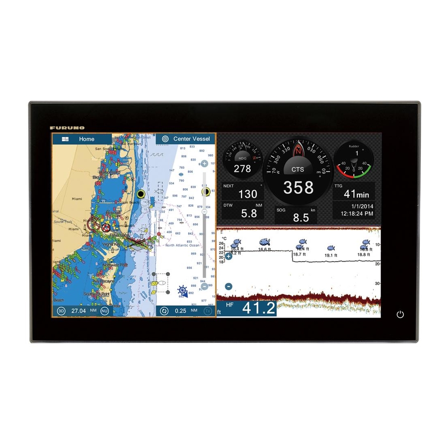
10. INSTRUMENT DISPLAY The instrument display provides comprehensive navigation and environment data. The instrument display can be programmed to a full screen or three-way split screen. Applicable sensors are required. 10.1 How to Show the Instrument Display Set the instrument display on the home screen referring to paragraph 1.7.1. Tap the instrument display icon to show the instrument display. -
Page 179: Instrument Displays
10. INSTRUMENT DISPLAY 10.2 Instrument Displays This section provides examples of the available instrument displays, with their default configurations. Your displays may be different depending on your system configura- tion. The instrument theme is available in black (default color) or white. The sample dis- plays shown in this chapter use the white theme. - Page 180 10. INSTRUMENT DISPLAY Single engine display Twin engines display 10-3...
- Page 181 10. INSTRUMENT DISPLAY Tri engines display Quad engines display 10-4...
-
Page 182: Split Screen Displays
10. INSTRUMENT DISPLAY 10.2.2 Split screen displays Navigation display Environment display Wind display 10-5... - Page 183 10. INSTRUMENT DISPLAY Numeric display Highway display NAVpilot display 10-6...
- Page 184 10. INSTRUMENT DISPLAY Single engine display Twin engines display Triple engines display 10-7...
- Page 185 10. INSTRUMENT DISPLAY Tank display The tank indication shows fuel level in both analog and digital formats. The analog in- dicator rises or lowers with fuel level and the color changes according to the percent- age of fuel remaining. Green: 10% - 100% Red: 0% - 10% 10-8...
-
Page 186: How To Switch Between Instrument Displays
10. INSTRUMENT DISPLAY 10.2.3 How to switch between instrument displays 3-way split screen The default display screens in the 3-way split screen are environment, wind, numeric, highway, NAVpilot, single engine, twin engines, triple engines, and tank. The availabil- ity of a display depends on your system configuration. You can switch between the displays by swiping downward at the bottom of the dis- play, or tapping the screen to display the pop-up menu shown below and tapping the display of your choice. - Page 187 10. INSTRUMENT DISPLAY Full screen The default full screens are [Full 1], [Full 2], [Single Engine], [Twin Engines], [Tri En- gines], and [Quad Engines]. (The availability of the displays depends on your system configuration.) You can switch between the displays by swiping downward at the bot- tom of the display, or tapping the screen to display the pop-up menu shown below and tapping the display of your choice.
-
Page 188: How To Edit The Instrument Displays
10. INSTRUMENT DISPLAY 10.3 How to Edit the Instrument Displays The instrument displays are fully customizable. You can edit the displays as follows: • Remove an indication from a display • Add an indication to a display • Rearrange the indications in a display •... -
Page 189: How To Edit, Remove An Indication In An Instrument Display
10. INSTRUMENT DISPLAY 10.3.3 How to edit, remove an indication in an instrument display 1. Prepare the display for editing as shown in paragraph 10.3.1. 2. Tap the indication to process to show the [Edit Instrument] pop-up menu. 3. Do one of the following depending on your objective: •... - Page 190 10. INSTRUMENT DISPLAY • Change the indication type: Tap [Change Type] to show the [Edit Instrument] pop-up menu, shown on the next page. [GRAPHIC] changes the size of a graphic indication or changes a numeric indication to the corresponding graphic indication.
-
Page 191: How To Add An Indication To An Instrument Display
10. INSTRUMENT DISPLAY 10.3.4 How to add an indication to an instrument display 1. Prepare the display for editing as shown in paragraph 10.3.1. 2. Tap an unoccupied position on the display to show the [Add Instrument] pop-up menu. (If there is no space available, remove an unnecessary indication following the procedure in paragraph 10.3.3.). -
Page 192: How To Add An Instrument Display
10. INSTRUMENT DISPLAY 10.3.7 How to add an instrument display Ten full size and six split screen instrument displays are preset in this equipment. If the displays do not meet your requirements, you may add custom displays as neces- sary. A maximum of ten each of full screen and split screen displays is available. 1. -
Page 193: Instrument Theme
10. INSTRUMENT DISPLAY 10.4 Instrument Theme The instrument theme is available in black or white. To change the theme, go to the home screen and tap [Settings] - [General]. Set [Instrument Theme] to [Black] or [White]. The setting also controls the graphic format navigation data displays in the data area. -
Page 194: 11. Weather
U.S. Information provided by the Sirius Marine Weather service is advisory in nature. You, the customer, agree to release FURUNO ELECTRIC CO., LTD., Sirius Satellite Radio Inc., Navcast Inc. and WSI Corporation from any problems that occur from this ser- vice. -
Page 195: Navcenter Weather
11. WEATHER How to select the weather display The weather display is overlaid on the 2D plotter display. Select the weather display on the home screen. Weather display 11.2 NavCenter Weather You can download the NavCenter data from the internet via Wireless LAN. See section 1.18 for how to connect to the internet. - Page 196 11. WEATHER 4. Tap [Tidal Step]. 5. Tap the update interval (which determines how often tidal data are captured) for the tide icon. 6. Tap [Duration of Animation]. 7. Tap the update interval for the animation. The larger the time, the slower the ani- mation moves.
-
Page 197: How To Download The Navcenter Weather Data
11. WEATHER 11.2.2 How to download the NavCenter weather data 1. Open the home screen, then tap [Settings] - [General]. 2. Tap [Wireless LAN Settings]. 3. Turn on [Wireless]. 4. After the internet connection is established, tap the close button to exit. 5. -
Page 198: How To Display The Navcenter Data
11. WEATHER 11. Open the weather display, then tap the screen to show the pop-up menu. Tap [Get Latest Wx]. The notification bar at the top of the screen flashes "Weather Update in Progress" during the downloading. If the downloading was successful, the message " DOWN- LOAD SUCCEEDED"... -
Page 199: How To Load A Weather File
11. WEATHER 11.2.4 How to load a weather file You can load a weather file saved on a micro SD card. 1. Set the applicable micro SD card in the SD card unit. 2. Open the home screen, then tap [Settings] - [Weather]. 3. -
Page 200: How To Display The Sirius Data
11. WEATHER 11.3.2 How to display the Sirius data [Wx Radar] (Weather radar) NOWRAD and Canadian weather radar information are put on top of your chart (see paragraph 11.3.1). This display lets you see possible storm fronts to help you identify the clouds from possible sea clutter. -
Page 201: Weather Icons (Sirius Weather)
11. WEATHER [Anim Radar] (Animation radar) The animation radar display provides the past weather radar information. To show the animation radar display, tap [Anim Radar] on the pop-up menu. To stop the animation display, tap [End Anim] at the top right-hand corner of the screen. 11.4 Weather Icons (Sirius Weather) The table below shows the weather icons that appear on the Sirius weather display. -
Page 202: Weather Data (Navcenter Or Sirius)
11. WEATHER 11.5 Weather Data (NavCenter or Sirius) The table below shows the weather data available for displaying according to weather data server (NavCenter or Sirius). Items NavCenter Sirius Item NavCenter Sirius Wind Currents Waves Altimetry Plankton Cloud Buoys Rain City Pressure Storm... - Page 203 11. WEATHER [Rain/Snow]: The rain/snow fore- cast displays rain/snow images. 0.1 mm/hour of rainfall/snowfall (mini- mum) is displayed in green, 5 mm/ hour (maximum) in dark violet. 4,979 [Air Temp]: The air temp forecast displays the air temperature by col- or.
- Page 204 11. WEATHER Pressure icon Meaning Trough Squall line Dry line Isobars 1010 [500mb]: The 500mb forecast dis- plays the contour lines over 500 mb. 4,898 [SST] (Sea surface tempera- ture): This data layer shows the temperature of the sea surface in shades.
- Page 205 11. WEATHER [Currents]: The current forecast dis- plays the tidal current speed and di- rection by blue arrow. The darker the blue, the faster the current speed (0 to 2 kn). 1,621 [Altimetry]: The altimetry forecast displays the sea height anomalies by color.
-
Page 206: 12. Ais, Dsc Message
12. AIS, DSC MESSAGE 12.1 What is AIS? AIS (Automatic Identification System) is a system that continuously transmits the iden- tification and position of your ship to AIS-equipped ships within VHF range. All such ships also receive data from other AIS-equipped ships and display their positions and other relevant information. -
Page 207: Proximity Ais Target Alarm
12. AIS, DSC MESSAGE Target Symbol Description type Lost AIS An AIS target becomes a lost target target if a signal is not received from the AIS target for x* min- utes. The lost target symbol is erased if a signal is not re- Color - AIS target: Blue for the Class A AIS ceived for an additional x* min-... -
Page 208: How To Ignore Slow Moving Ais Targets
12. AIS, DSC MESSAGE 2. Turn on [Proximity AIS Target Alarm]. 3. Tap [Proximity AIS Target Alarm Value] to open the software keyboard. 4. Set the alarm value, then tap . 5. Tap the close button to finish. 12.5 How to Ignore Slow Moving AIS Targets The proximity AIS target alarm may often sound in areas of heavy vessel traffic. -
Page 209: How To Display An Ais Safety Message
[Target Info] window. If there is an AIS safety message (addressed or broadcast) from the ship, it appears at the top of the window. You can delete the message by tapping [Delete Message]. Name FURUNO MMSI 124365890 GALE WARNING 27.16N 82.40W 342.0°... -
Page 210: How To Show Or Hide The Target Ids
12. AIS, DSC MESSAGE 12.9 How to Show or Hide the Target IDs You can show or hide the target ID of AIS targets. 1. Open the home screen, then tap [Settings] - [Targets]. 2. Turn [Display Target IDs] on or off. 3. - Page 211 How to display the detailed information for an AIS target Tap the AIS target on the AIS list then tap [Detail]. The name of the AIS is shown in the title bar and navigation data appears in the [TARGET INFO] section. FURUNO FURUNO 000886617 How to find an AIS target on the plotter display Tap the AIS target on the AIS list, then tap [Find On Chart].
-
Page 212: How To Register An Ais Or Dsc Target To The Buddies List
12. AIS, DSC MESSAGE 12.11 How to Register an AIS or DSC Target to the Buddies List The buddies list provides a quick reference to ships’ MMSI and nickname. For exam- ple, you might want to enter the MMSI and nickname of partner ships or ships that of- ten operate in your area. -
Page 213: Ais Transponder Fa-30, Fa-50
12. AIS, DSC MESSAGE 12.12 AIS Transponder FA-30, FA-50 The FURUNO AIS Transponder FA-30 (or FA-50) installs in the NavNet TZtouch2 net- work and can be controlled from a NavNet TZtouch2 display. To access the menu for the transponder, do as shown below. See the respective operator’s manual for details. -
Page 214: 12.13 Dsc Message Information
12. AIS, DSC MESSAGE 12.13 DSC Message Information The DSC (Digital Selective Calling) message information feature provides, on the plot- ter and radar displays, the MMSI no. and position* of the ships that have transmitted a DSC message to you. A hexagon-shaped marker marks the position of the ship at the time the DSC was transmitted to you. -
Page 215: 3How To Display Dsc Information
12. AIS, DSC MESSAGE 12.13.3 How to display DSC information Tap a DSC marker to display the simple information (position, MMSI no. of the ship that transmitted a DSC message, etc.). To get detailed information, tap a DSC marker, then tap [Info] on the pop-up menu. 5.992 NM TCPA 41’30s... -
Page 216: 4The Dsc List
12. AIS, DSC MESSAGE 12.13.4 The DSC list The DSC list shows the name, MMSI, range, bearing, CPA and TCPA of vessels from which you have received a DSC message. 1. Open the home screen, then tap [Lists] - [DSC]. List sort buttons 2. - Page 217 12. AIS, DSC MESSAGE To see the detailed information for a DSC target, tap a DSC then tap [Detail]. To put a DSC marker at the center of the plotter display, tap the DSC target, then tap [Find On Chart]. 12-12...
-
Page 218: 13. Other Functions
13. OTHER FUNCTIONS Once you have become acquainted with your equipment, you can set it according to your needs. You can change system configuration, change how the equipment oper- ates and displays information, etc.The descriptions contained in this section are only those not previously mentioned. -
Page 219: Units Menu
13. OTHER FUNCTIONS 13.2 Units Menu The [Units] menu sets the unit of measurement for speed, distance, depth, etc. Menu item Options [Bearing Display] [Magnetic], [True] The mode (magnetic or true) of all heading and bearing data. [True Wind Calculation [Ground], [Surface] Reference] Select wind value to display from speed over ground or speed through... -
Page 220: Initial Setup Menu
13. OTHER FUNCTIONS 13.3 Initial Setup Menu The [Initial Setup] menu, which is mainly for use by the installer of the equipment, sets up the system according to the sensors connected. These adjustments require some knowledge of marine electronics equipment. If you are unsure of your abilities, have a qualified marine electronics technician make the adjustments. - Page 221 13. OTHER FUNCTIONS [Graphic Instruments Setup] - [Sea Surface Temperature] Menu Item Description Options (setting range) [Minimum Sea Surface Set the transducer’s minimum detectable 0.00°C to 99.99°C Temperature] temperature. [Maximum Sea Surface Set the transducer’s maximum detectable 0.01°C to 99.99°C Temperature] temperature.
- Page 222 Select the source for each data to input to the system. If two or more sources are connected for a data, select one using the pull-down dialog box. The FURUNO products are shown at the upper part of the list. [Sensor List] Show the information for sensors connected to your equipment.
- Page 223 13. OTHER FUNCTIONS FUSION section Menu item Description Options (setting range) [Connect to Connect to your Fusion equipment. Fusion] [Fusion Auto Set to [ON] to allow this unit to control the Fusion volume. Volume] [Minimum Set the minimum speed threshold. Exceeding this 0.0 kn to 19.9 kn Speed] speed activates volume auto control.
-
Page 224: Facsimile Receiver Fax-30
13. OTHER FUNCTIONS 13.4 Facsimile Receiver FAX-30 The FURUNO Facsimile Receiver FAX-30 installs in the NavNet TZtouch2 network and can be controlled from a NavNet TZtouch2 display. Below are the steps to start fax operation. 1. Connect the FAX-30 to the NavNet TZtouch2 network. -
Page 225: Software Update
13. OTHER FUNCTIONS 13.5 Software Update You can update the software for this equipment via the internet. See section 1.18 for how to connect to the internet. It is recommended to back up stored data (waypoints, routes, etc.) to a micro SD card before updating the software, in case something should go wrong during the updating. -
Page 226: How To Manage Your Charts
13. OTHER FUNCTIONS 13.6 How to Manage Your Charts The NavNet TZtouch2 uses the same Mapmedia charts as NavNet 3D. Even though NavNet TZtouch2 is a master-less system in networking, for charts one NavNet TZtouch2 unit should be set as Chart Master to share the System ID, which will be necessary to obtain an unlock code of a chart from Mapmedia. -
Page 227: How To Update Or Add Charts
Free (USA and NOAA) and for-fee NavNet TZtouch2 compatible charts are provided by FURUNO and Mapmedia. Go to the URLs shown below to download chart data. Download the chart file to your desktop. Unzip the file, then copy it to the root of a mi- cro SD card. -
Page 228: Maintenance, Troubleshooting
14. MAINTENANCE, TROUBLE- SHOOTING This chapter has information about maintenance and troubleshooting that the user can follow to care for the equipment. NOTICE WARNING Do not apply paint, anti-corrosive ELECTRICAL SHOCK HAZARD Do not open the equipment. sealant or contact spray to plastic parts or equipment coating. -
Page 229: Fuse Replacement
The life of the LCD is approximately 18,000 hours for the TZTL15F, and 25,000 hours for the TZTL12F. The actual number of hours depends on ambient temperature and humidity. When the brilliance cannot be raised sufficiently, contact your dealer about replacement of the LCD. -
Page 230: Troubleshooting
14. MAINTENANCE, TROUBLESHOOTING 14.4 Troubleshooting This section provides simple troubleshooting procedures that the user can follow to re- store normal operation. If you cannot restore normal operation, do not check inside the unit. Have a qualified technician check the equipment. 14.4.1 General troubleshooting Problem... -
Page 231: Fish Finder Troubleshooting
14. MAINTENANCE, TROUBLESHOOTING 14.4.4 Fish finder troubleshooting Problem Remedy You selected a fish finder dis- • Check that the transducer cable is tightly fastened. play, but no picture appears. • Check that the fish finder source is correct. • If you are using a network fish finder, check that it is properly connected. -
Page 232: Appendix 1 Menu Tree
APPENDIX 1 MENU TREE Settings General Function Gesture (None, Screen Capture, Event, Home, Settings, Lists, Tide) Connect to the Internet (Never, At Startup, When Necessary) Wireless LAN Settings (Open the dialog box for Wireless LAN settings.) User Interface Auto-Hide (0’03s, 0’05s, 0’10 s, 0’15s) Instrument Theme (White, Black) Cross Cursor Speed (1 - 20, 8) Bold italic: Default setting... - Page 233 APPENDIX 1 MENU TREE Points Display Points Names (ON, OFF) Default Point Symbol (Select the default icon for point.) Default Point Color (Red, Blue, Green, Yellow, Magenta, Orange, Cyan, Black) Point Size (50 - 200(%), 100) Icons Set (Modern, Classic) Data to Be Recorded in Event Comment (None, Date, SST, Date And SST) Record Event1 Automatically (ON, OFF) Default Event 1 - 6 Symbol...
- Page 234 APPENDIX 1 MENU TREE Plotter Grid Interval (Off, Very Small, Small, Medium, Large, Very Large) Show Scale Slider (OFF, ON) Tide/Current Icons Size (50 - 150(%), 100) NavData Transparency (0 - 80(%), 10) PhotoFusion Transparency (0 - 80(%), 15) Tide Range for PhotoFusion (0.0 - 60(ft), 0) Tidal Currents Transparency (0 - 80(%), 25) Radar Transparency (0 - 80(%), 20) Range Link (ON, OFF)
- Page 235 APPENDIX 1 MENU TREE S-52 S-52 Vector Chart Display Mode (Custom, Base, Standard, Other, Fishing) Display Unknown Object (ON, OFF) Chart Data Coverage (ON, OFF) Water and Seabed Features (ON, OFF) Traffic Routes (ON, OFF) Information Areas (ON, OFF) Buoys & Beacons (ON, OFF) Lights (ON, OFF) Fog Signals (ON, OFF) Radar (ON, OFF)
- Page 236 APPENDIX 1 MENU TREE Radar Radar Source (Select the antenna host name.) Day Background Color (Black, Dark Blue, White) Night Background Color (Black, Dark Blue) Echo Color (Multicolor, Green, Yellow) Rings Interval (Auto, 1, 2, 3, 4, 5, 6, 7, 8, 9) Show Range Slider (ON, OFF) Own Ship Icon (ON, OFF) Bearing Scale Mode (Relative, True)
- Page 237 APPENDIX 1 MENU TREE Sounder Fish Finder Source (TZTL, network sounder name if connected) Day Background Color (White, Light Blue, Black, Dark Blue) Night Background Color (Black, Dark Blue) Echo Color Levels (8 Colors, 16 Colors, 64 Colors) Show Range Slider (ON, OFF) A-Scope Peak Hold (ON, OFF) Zoom Reference Lines (ON, OFF) Smoothing (ON, OFF)
- Page 238 APPENDIX 1 MENU TREE Alarm Hardware Alarm (ON, OFF) XTE Alarm (ON, OFF) Depth Alarm (ON, OFF) Depth Alarm Value (0 - 900(ft), 30) Sea Surface Temperature Alarm (Off, Over, Under, Within, Out of) °F Temperature Alarm Value (32 - 140( ), 70.00) °F Temp.
- Page 239 APPENDIX 1 MENU TREE Camera VIDEO INPUT 1 Connected (ON, OFF) NickName (Camera 1) VIDEO INPUT 2 Connected (ON, OFF) NickName (Camera 2) CONTROLLABLE CAMERA FLIR Installation Scan IP FLIR IP Video Source (None, Camera 1, Camera 2) ° Camera Offset (Right-left) (0 °...
- Page 240 APPENDIX 1 MENU TREE DATA ACQUISITION GP330B WAAS Mode WS200 WAAS Mode Data Source Sensor List NMEA 0183 Output NMEA 2000 PGN Output Sky View INTERNAL GPS SETUP WAAS Mode SC-30 SETUP WAAS Mode Heading Offset Pitch Offset Roll Offset CALIBRATION Heading Speed Through Water...
-
Page 241: Appendix 2 Radio Regulatory Information
APPENDIX 2 RADIO REGULATORY INFORMATION Wireless Interoperability This product is designed to be interoperable with any wireless LAN product that is based on direct sequence spread spectrum (DSSS) and orthogonal frequency division multiplexing (OFDM) radio technology and to comply with the following standards. •... - Page 242 APPENDIX 2 RADIO REGULATORY INFORMATION USA-Federal Communications Commission (FCC) Below are descriptions for built-in Wireless LAN module. This equipment has been tested and found to comply with the limits for a Class B digital device, pursuant to Part 15 of FCC Rules. These limits are designed to provide reasonable protection against harmful interference in a residential installation.
- Page 243 APPENDIX 2 RADIO REGULATORY INFORMATION Canada-Industry Canada (IC) Below are descriptions for built-in Wireless LAN module. This device complies with RSS 210 of Industry Canada. Operation is subject to the following two conditions: (1) This device may not cause interference, and (2) This device must accept any interference, including interference that may cause undesired op- eration of this device.
- Page 244 12.1-inch wide TFT color LCD, 1280 x 800 (WXGA) TZTL15F 15.6-inch full-wide TFT color LCD, 1366 x 768(FWXGA) Brightness 1300 cd/m typical (TZTL12F), 1100 cd/m typical (TZTL15F) Display colors 16,770,000 colors (plotter), 64 colors (echo), 16 colors (radar) PLOTTER FUNCTION...
- Page 245 FURUNO TZTL12F/15F Notification DSC receiving, Waypoint crossing, End of route, AIS target count, NAVpilot engagement (NAVpilot-700 required) INTERFACE Number of port 1 port, Ethernet 100Base-TX NMEA2000 1 port (LEN=1), external power input required 1 port, USB2.0 Video output 1 port, HDMI (720 p)
- Page 246 INDEX Numerics clearing lost target ......... 6-24 CPA/TCPA alarm ........6-25 2D/3D switch ..........3-2 3D display manual target acquisition ...... 6-23 showing/hiding display ......6-22 activating ..........3-2 stop tracking target........ 6-24 description ..........3-1 target data ..........6-24 exaggeration ...........
- Page 247 INDEX Fish finder alarm activating/deactivating......7-12 Data area Fish finder automatic operation....7-5 adding data to ........1-16 contents of data box.......1-16 Fish finder manual operation......7-6 FLIR camera data format (analog or digital) ....1-18 controlling..........9-4 deleting data box from......1-17 setting............9-2 description..........1-15 Function gesture ........1-27 order of data...........1-15 Fuse replacement ........14-2 transparency ..........1-18...
- Page 248 INDEX LCD life ........... 14-2 moving point to screen center ....4-10 LCD replacement ........14-2 points used display........4-5 restarting navigation to ......4-15 showing/hiding point names ....4-10 Magnetron replacement ......14-2 stopping navigation to ......4-15 Maintenance..........14-1 Points list...........
- Page 249 INDEX importing ..........8-2 System configuration........xiii inserting route points........5-3 moving route points........5-4 Temperature graph ........7-16 navigation from selected route point ..5-10 Tidal current graph ........3-11 removing points........5-4 Tidal current overlay restarting navigation.......5-11 displaying ..........3-10 routes list..........5-5 icon size ..........3-10 routes menu ...........5-15 information display .........3-10 routes used display ........5-7 Tide graph ..........3-9...
- Page 250 INDEX NavCenter data download..... 11-4 NavCenter weather file......11-6 NavCenter weather setup ..... 11-2 selecting ..........11-2 Sirius ............. 11-6 Wx radar..........11-7 Wireless LAN connect to existing ........ 1-30 creating network ........1-31 forget all ..........1-31 wireless terminal operation....1-32 Wireless terminal operation.....
Need help?
Do you have a question about the TZTL12F and is the answer not in the manual?
Questions and answers