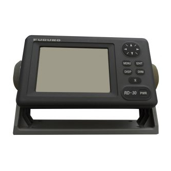
Furuno RD-30 Operator's Manual
Multi display
Hide thumbs
Also See for RD-30:
- Installation manual (22 pages) ,
- Operator's manual (2 pages) ,
- Specifications (2 pages)
Table of Contents
Advertisement
Advertisement
Table of Contents

Related Manuals for Furuno RD-30


Summary of Contents for Furuno RD-30
- Page 1 Back MULTI DISPLAY RD-30...
- Page 2 Printed in Japan Printed in Japan All rights reserved. All rights reserved. PUB.No. OME-44130 PUB.No. OME-44130 ( ( DAMI DAMI ) ) RD-30 RD-30 Your Local Agent/Dealer Your Local Agent/Dealer FIRST EDITION : FIRST EDITION : MAR. MAR. 2001 2001 : : MAR.
- Page 3 Immediately turn off the power at the switchboard if the equipment is emitting smoke or fire. Continued use of the equipment can cause fire or electrical shock. Contact a FURUNO agent for service. Keep heater away from equipment. A heater can melt the equipment's power cord, which can cause fire or electrical shock.
-
Page 4: Table Of Contents
TABLE OF CONTENTS FOREWORD ... iii SYSTEM CONFIGURATION ... iv 1. OPERATION ...1-1 1.1 Controls... 1-1 1.2 Turning On/Off the Power ... 1-2 1.3 Adjusting Key Panel Dimmer, Display Contrast ... 1-2 1.4 Selecting a Display ... 1-3 1.4.1 Sample displays ... 1-4 1.5 Setting up the Displays ... -
Page 5: Foreword
Thank you for considering and purchasing FURUNO. Features The RD-30 accepts a wide variety of navigation data and displays them in digital, graph and graphic (analog) formats. The user may arrange the data in five displays and show those displays in the order desired. -
Page 6: System Configuration
SYSTEM CONFIGURATION MULTI DISPLAY RD-30 FURUNO MENU DISP : Supplied : Option Example of single display unit connection FURUNO FURUNO MULTI DISPLAY RD-30 FURUNO Note: Additonal power supply may be added to maintain minimum voltage. Example of multiple display unit connection... -
Page 7: Operation
MENU key: Opens/closes the menu. FURUNO How to remove the cover Cursor pad: Shifts highlight cursor. MENU DISP RD-30 key: Displays Rx data. DISP key: Selects a display. RD-30 Press here and pull toward you to remove cover. ENT key: Registers menu options. -
Page 8: Turning On/Off The Power
1. OPERATION Turning On/Off the Power Turning on: Press the [PWR] switch. Release it when you hear a beep. The screen shows the last-used display. Turning off: Press the [PWR] switch. Release it when the screen becomes blank. Adjusting Key Panel Dimmer, Display Contrast 1. -
Page 9: Selecting A Display
Selecting a Display The RD-30 has four display types, digital, graph, graphic (analog) and highway. The operator may arrange data for five displays and show them in the order desired. Availability of data depends on the sensors connected. Press the [DISP] key consecutively to select a display. Below is the default display sequence and default digital data items. -
Page 10: Sample Displays
1. OPERATION 1.4.1 Sample displays Graph displays Water temperature, depth, speed over ground, speed through water, wind, current data and atmospheric pressure can be shown in graph form. TEMP (5 MIN ) Water temperature graph 14.6KT (5 MIN ) Speed over ground graph WIND (5 MIN ) Wind graph... - Page 11 Graphic displays The graphic display presents speed, temperature, wind, compass and current data in analog and digital formats. SOG: SPEEDOMETER1 STW: SPEEDOMETER2 Speedometer graphic display 57.0 10.2 Compass graphic display : Active readout : Inactive readout WIND TRUE APP 104.7 Wind graphic display 10 20 30 PORT...
- Page 12 1. OPERATION The highway display The highway display provides a graphic presentation of ship’s progress towards a destination, together with range and bearing to the destination, and ship’s course and speed. To choose this display, select HIGHWAY from the USER DISPLAY SETUP menu, referring to the procedure on page 1-8.
- Page 13 Selecting the display range for the highway display You may select the display range for the highway display among 0.2, 0.4, 0.8, 1, 2, 4, 8 and 16 nautical miles. (Nautical miles is the default range unit; kilometer and statute mile are also available. See page 1-23.) 1.
-
Page 14: Setting Up The Displays
1. OPERATION Setting up the Displays Four display types are available: digital, graph, graphic, and highway. You may freely select and arrange what data to display in the digital, graph and graphic displays. The order in which displays are shown may also be changed. Note that the highway display cannot be adjusted. -
Page 15: Setting Up Digital Displays
1.5.2 Setting up digital displays 1. Select DIGITAL referring to paragraph 1.5.1. 2. Press the [ENT] key to show the digital display division options window. Digital display division options window 3. Select the display division desired, that is, the number of indications to show on a digital display, and then press the [ENT] key. -
Page 16: Setting Up Graph Displays
1. OPERATION 5. Use the cursor pad to select “A” and then press the [ENT] key. The data available for display is shown. 6. Select data desired and then press the [ENT] key. (All data require appropriate sensors.) NONE: No display TEMP: Water temperature DEPTH: Depth... - Page 17 Graph display options window 3. Choose the graph display option desired and then press the [ENT] key. One of the following graph display setup menus appears depending on your selection. GRAPH < TEMP GRAPH SETUP BASE POINT : + 50 °...
- Page 18 1. OPERATION 4. Use the cursor pad to select an item and then press the [ENT] key. The far-left digit is selected by the cursor in the case where you enter data, or a pop window appears with options. Enter and select data referring to the table below.
-
Page 19: Setting Up Graphic Displays
1.5.4 Setting up graphic displays 1. Select GRAPHIC referring to paragraph 1.5.1. 2. Press the [ENT] key to show the graphic display options window. 3. Select graphic display desired and then press the [ENT] key. For water temperature, speedometer1 or speedometer2 one of the following displays appears;... -
Page 20: Displaying Rx Data
1. OPERATION Displaying Rx Data Data currently being received can be shown by using the [*] key. Below is a sample Rx data display. POSN 122 50.952'W TIME TEMP DEPTH WIND CURENT PRESSURE AIR TEMP HUMIDITY ODOMETER TRIPMETER 01-FEB-04 10:04:06 1-14 [*] Key 37 59.882'N... -
Page 21: Alarms
Alarms The RD-30 has ten conditions which can trigger audio and visual alarms: speed, water temperature, depth, arrival/anchor watch, cross-track error, trip distance (two alarms), countdown timer, alarm clock, no position fixing and no position data. Note: You can not turn off the no position fixing alarm nor the no position data alarm. -
Page 22: Speed Alarm
1. OPERATION 1.7.2 Speed alarm The speed alarm warns when your boat’s speed is lower or higher than the speed setting, or is inside or outside of the speed range setting. 1. Press the [MENU] key once or twice to show the main menu. 2. -
Page 23: Depth Alarm
4. Select alarm type desired and then press the [ENT] key. OFF: Turns off the water temperature alarm. LOW: Alarm triggered when the water temperature is lower than the water temperature setting. HIGH: Alarm triggered when the water temperature is higher than the water temperature setting. -
Page 24: Arrival Alarm, Anchor Watch Alarm
1. OPERATION 1.7.5 Arrival alarm, anchor watch alarm The arrival alarm informs you that your boat is approaching a destination waypoint. The area that defines an arrival zone is that of a circle which you approach from the outside of the circle. The alarm will be released if your boat enters the circle. -
Page 25: Xte (Cross Track Error)
5. If you turned on the alarm, press the [ENT] key and then use the cursor pad to enter the alarm setting: Use ◄ or ► to select location, and press ▲ or ▼ to enter value. 6. Press the [ENT] key. 7. -
Page 26: Odometer Alarm
1. OPERATION 1.7.8 Odometer alarm The odometer alarm informs you when your vessel has traveled the distance you have set. Its function is similar to the trip alarm except its maximum setting is 999 (nm). 1. Press the [MENU] key once or twice to show the main menu. 2. -
Page 27: Alarm Messages
Messages display 3. Press the [MENU] key twice to close the menu. Note: “NO FIX!” appears when a navigation device connected to the RD-30 can not fix the ship’s position. “NO POSITION DATA!” appears when the own ship’s position data has not been input from a navigation device for 90 seconds. -
Page 28: 1.8 Resetting Indications To Zero
1. OPERATION 1.8 Resetting Indications to Zero You may individually reset the trip, odometer and graph indications to zero as follows: 1. Press the [MENU] key once or twice to display the main menu. 2. Select RESET and then press the [ENT] key. 3. -
Page 29: Choosing Units Of Measurement
Choosing Units of Measurement You may choose the units of measurement for water temperature, distance/speed, depth and wind speed as follows: 1. Press the [MENU] key once or twice to display the main menu. 2. Select UNITS and then press the [ENT] key. 3. -
Page 30: Applying An Offset To Data
1. OPERATION 1.10 Applying an Offset to Data An offset may be applied to speed, water temperature, depth and wind data to refine their accuracy. Further, you can use local time by entering the time difference between it and UTC time. 1. -
Page 31: Choosing Time Display Format
1.11 Choosing Time Display Format Time may be displayed in 12 hour or 24 hour notation as follows: 1. Press the [MENU] key once or twice to display the main menu. 2. Select SYS SETUP and then press the [ENT] key. 3. -
Page 32: Choosing Position Data Format
1. OPERATION 1.12 Choosing Position Data Format Position may be shown in latitude and longitude or Loran/ Decca TDs. Choose L/L position format and Loran/ Decca chain and station pair as follows: 1. Press the [MENU] key once or twice to display the main menu. 2. -
Page 33: Simulation Mode
Simulation Mode A simulation mode, showing internally generated navigation data, is provided to acquaint you with the features of the RD-30. “SIM” appears on the display when the simulation mode is turned on. 1. Press the [MENU] key once or twice to open the main menu. -
Page 34: Bearing Reference
True Bearing = Magnetic Bearing +Magnetic Deviation (Variation). Magnetic bearings are measured with magnetic north as the reference direction. Magnetic bearing is calculated by adding true bearing to RD-30-stored magnetic variation. “M” appears near a bearing readout when magnetic bearings are used. -
Page 35: Magnetic Variation
4. Choose MAGNETIC or TRUE as appropriate and then press the [ENT] key. 5. Press the [MENU] key twice to close the menu. 1.16 Magnetic Variation The location of the magnetic north pole is different from the geographical north pole. This causes a difference between the true and magnetic north direction. This difference is called magnetic variation, and varies with respect to the observation point on earth. -
Page 36: Heading Sensor Pg-1000, C-2000 Setup
1. OPERATION 1.17 Heading Sensor PG-1000, C-2000 Setup Set up the heading sensor PG1000, C-2000 on the HDG SETUP menu, with the heading sensor connected to the AUX port. Note that no data is transmitted from the IN/OUT port when the HDG SETUP menu is displayed. Calibration Calibrate the heading sensor against magnetic field distortion aboard the boat as below. - Page 37 6. Choose YES and then press the [ENT] key. The display shows “CALIBRATION??” during calibration. (To cancel calibration, press the [MENU] key. You cannot cancel calibration except when SAMPLING is showing “??”.) 7. Continue turning the boat in a circle until calibration results, NG (No Good) or OK, appear on the display.
- Page 38 1. OPERATION Offset If there is a difference between sensor bearing and actual bearing, enter it as below. For example, if the sensor shows 70° and the actual bearing is 75°, enter +5(°). 10. Choose OFFSET and press the [ENT] key. 11.
-
Page 39: Maintenance, Troubleshooting
– they can remove paint and markings. Error Messages In addition to the alarm messages mentioned in Chapter 1, the RD-30 displays the following messages to alert you to possible trouble. Message BACKUP ERROR DATA! -
Page 40: Diagnostic Test
2. MAINTENANCE, TROUBLESHOOTING Diagnostic Test The diagnostic test checks the ROM, RAM, AUX port, IN/OUT port, internal battery, keyboard and LCD for proper operation. Additionally it displays power source voltage, contrast and dimmer settings and program version number. 1. Press the [MENU] key once or twice to open the menu. 2. -
Page 41: When Battery Alarm! Appears
8. The equipment beeps and then displays the following message to inform you that it is now going to check the LCD: 9. The LCD is checked and then the entire test is repeated. To stop the test, turn off the power. When BATTERY ALARM! Appears A lithium battery (type: CR2354-1F2, code no.: 000-142-305) is installed on the circuit board inside the display unit, and it preserves data when the power is... -
Page 42: Clearing Backup Data
2. MAINTENANCE, TROUBLESHOOTING 5. Press any key to shut down the equipment. 6. Have a qualified technician replace the battery. Clearing Backup Data You may clear all backup data (menu settings, trip, graph and odometer readings, etc.) to start afresh. 1. -
Page 43: Menu Tree
MENU TREE MENU 1: DIGITAL USER 2: DIGITAL DISP 3: DIGITAL 4: DIGITAL 5: DIGITAL Options 2-5 same as that for 1. ALARM1 ALARM2 MESSAGES (Message board) RESET (Continued on next page) DIGITAL (Data Available: NONE, TEMP, POSN, HDG, ODO, CUR, HUM, SOG, DEPTH, TIME, WPT, ROT, XTE, POWER, PRE, STW, WIND, COG, TRIP, TD, TIMER, A-TEMP;... - Page 44 (Continued from previous page) OFFSETS SYS SETUP I/O SETUP TD SETUP LANGUAGE UNITS HDG SETUP (w/connection of PG-1000, C-2000) *= APB, BWC, BWR, CUR, DBK, DBS, DBT, DPT, GGA, GLC, GLL, GTD, TIME DIFF (-13:30 - +13:30, +00:00 ) SPEED(SOG) (-99.9 - +99.9, +0.0 kt ) SPEED(STW) (-99.9 - +99.9, +0.0 % ) °...
-
Page 45: Loran C/ A Chains
LORAN C/ A CHAINS Loran C Chain l a r f l u t i d l a r c i f Ø t l y Loran A Loran A station pair (Cannot enter same pair.) 1L0, 1L1, 1L4, 1L5, 1L6, 1L7, 1S1, 1S2, 1S3, 1S4, 1S6, 2H5, 2H6, 2S0, 2S1, 2S2, 2S3, 2S4, 2S5, 2S6, 2S7 c i f l a r... -
Page 46: Decca Chains
DECCA CHAINS Chain Chain Chain code South Baltic Vestlandet Southwest British Northumbrian Holland North British Lofoten North Baltic North West Trondelag English North Bothnian Southern Spanish North Scottish Gulf of Finland Danish Irish Finnmark French South Bothnian Hebridean Frisian Islands Helgeland Chain Location... -
Page 47: Specifications
Relative Humidity Waterproof Vibration COATING COLOR Display Unit Cover: 2.5GY5/1.5, Panel: N3.0 RD-30 95 x 60 mm (120 x 64 dot matrix) 1/2/3/4 data, Highway, Graph, Alphanumeric Water temperature, Water depth, Ship’s speed, Wind speed, Current speed/bearing IEC 61162-1/NMEA 0183 GGA>RMC>GLL... - Page 48 This page is intentionally left blank.
-
Page 49: Index
INDEX * key ...1-14 Alarms anchor watch ...1-18 arrival ...1-18 audio ...1-15 countdown...1-20 depth ...1-17 messages ...1-21 odometer...1-20 speed ...1-16 time ...1-20 trip ...1-19 water temperature...1-16 XTE (cross track error) ...1-19 Anchor watch alarm ...1-18 Arrival alarm ...1-18 Audio alarm ...1-15 Backup data erasure...2-4 Battery replacement...2-3 Bearing reference ...1-28...
Need help?
Do you have a question about the RD-30 and is the answer not in the manual?
Questions and answers