Furuno TZT16X Installation Manual
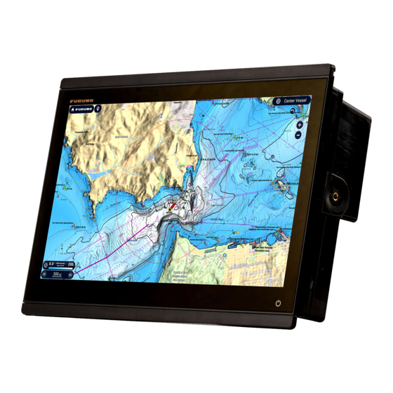
Multi function display
Hide thumbs
Also See for TZT16X:
- Installation manual (74 pages) ,
- Faq (19 pages) ,
- Operator's manual (21 pages)
Table of Contents
Advertisement
Quick Links
Installation Manual
MULTI FUNCITON DISPLAY
TZT16X/TZT22X/TZT24X
Model
SAFETY INSTRUCTIONS ................................................................................................ i
SYSTEM CONFIGURATION .......................................................................................... iii
EQUIPMENT LISTS......................................................................................................... v
1. MOUNTING..............................................................................................................1-1
1.1 Installation of Multi Function Display..................................................................................1-1
1.2 Flush Mounting ..................................................................................................................1-2
1.3 Desktop Mounting (TZT16X only, option) ..........................................................................1-5
1.4 Installation of Transducers (TZT16X only).........................................................................1-6
2. WIRING....................................................................................................................2-1
2.1 Interface Connections (rear of the unit) .............................................................................2-1
2.2 Power Cable ......................................................................................................................2-2
2.3 Grounding Wire (16X only) ................................................................................................2-3
2.4 MULTI Cable......................................................................................................................2-3
2.5 DRS Radar Sensor Connections .......................................................................................2-4
2.6 Network Connection with Other TZT Series Units .............................................................2-4
2.7 NMEA 2000 Connector ......................................................................................................2-4
2.8 Example TZT16X/22X/24X System Configuration.............................................................2-9
3. HOW TO SET UP THE EQUIPMENT......................................................................3-1
3.1 How to Set Time Zone, Time Format and Language.........................................................3-3
3.2 How to Set Units of Measurement .....................................................................................3-4
3.3 Initial Setup ........................................................................................................................3-5
3.4 How to Set Up the Radar (For the service technician only) .............................................3-11
3.5 How to Set Up the Fish Finder.........................................................................................3-13
3.6 Wireless LAN Setting .......................................................................................................3-19
3.7 Ferry Mode.......................................................................................................................3-21
3.8 How to Manage Your Charts............................................................................................3-21
3.9 IP Camera Setup .............................................................................................................3-26
PACKING LIST(S) ....................................................................................................... A-1
OUTLINE DRAWING(S) .............................................................................................. D-1
INTERCONNECTION DIAGRAM(S) ........................................................................... S-1
www.furuno.com
All brand and product names are trademarks, registered trademarks or service marks of their respective holders.
Advertisement
Table of Contents

Related Manuals for Furuno TZT16X


Summary of Contents for Furuno TZT16X
-
Page 1: Table Of Contents
EQUIPMENT LISTS......................v 1. MOUNTING......................1-1 1.1 Installation of Multi Function Display..................1-1 1.2 Flush Mounting ........................1-2 1.3 Desktop Mounting (TZT16X only, option) ................1-5 1.4 Installation of Transducers (TZT16X only).................1-6 2. WIRING........................2-1 2.1 Interface Connections (rear of the unit) ................2-1 2.2 Power Cable ........................2-2 2.3 Grounding Wire (16X only) ....................2-3... - Page 2 ・FURUNO Authorized Distributor/Dealer 9-52 Ashihara-cho, Nishinomiya, 662-8580, JAPAN A : AUG 2023 Printed in Japan All rights reserved. C : MAR . 22, 2024 Pub. No. IME-45240-C (TEHI ) TZT24X/TZT22X/TZT16X 0 0 0 2 0 0 1 4 3 1 2...
-
Page 3: Safety Instructions
Connection of an incorrect power Model compass compass supply can cause fire or damage the equipment. 0.60 m 0.95 m TZT16X If your vessel is configured with 1.15 m 0.75 m TZT22X an autopilot system, install an 0.95 m 0.60 m... - Page 4 SAFETY INSTRUCTIONS WARNING The radar antenna sends electromagnetic radio frequency (RF) energy. This energy can be dangerous to you, especially your eyes. Do not look at the radiator or near the antenna when the antenna is rotating. The distances at which RF radiation levels of 100 W/m and 10 W/m exist are shown in the table.
-
Page 5: System Configuration
1920×1080 (16:9 aspect ratio) and have HPD (Hot Plug Detection). . : Only DRS6A-NXT supports 12 to 24 V.DC : DRS4D X-Class can only be used in Japan. : DRS2D-NXT and DRS4D-NXT cannot be used in Japan. : Only TZT16X is supported. - Page 6 SYSTEM CONFIGURATION TZT series network connections The TZT series can be connected on the same network in the following combinations. TZtouch: TZtouch2: TZtouch2: TZtouch3: TZT9/14/BB TZTL12F/15F TZT2BB TZT9F/12F/16F/19F TZtouchXL: TZT16X/22X/ : Version 9.70 or later : Version 3.70 or later...
-
Page 7: Equipment Lists
EQUIPMENT LISTS Standard supply Name Type Code No. Remarks Multi Function Display TZT16X Including installation materi- als, accessories and spare TZT22X parts. TZT24X Optional supply Name Type Code No. Remarks NMEA Data Converter IF-NMEA2K2 000-020-510 Remote Control Unit MCU-005 000-035-097... - Page 8 EQUIPMENT LISTS Name Type Code No. Remarks 520-5PSD 000-015-204 For TZT16X only. Transducer* 520-5MSD 000-015-212 525-5PWD 000-027-447 520-PLD 000-023-680 525T-BSD 000-023-020 525T-PWD 000-023-019 SS60-SLTD/12 000-023-676 SS60-SLTD/20 000-023-677 525T-LTD/12 000-023-679 525T-LTD/20 000-023-678 50/200-1T *10M* 000-015-170 For TZT16X only. Require MB-1100 for...
- Page 9 EQUIPMENT LISTS Other compatible transducers (local supply) The transducers (Manufactured by AIRMAR Technology Corporation) listed in the table below are compatible with this equipment. Single Frequency CHIRP (For internal fish finder) Output power Model 300 W B150M SS75L P95M 600 W B75M B785M SS75M...
- Page 10 EQUIPMENT LISTS This page is intentionally left blank. viii...
-
Page 11: Mounting
MOUNTING Installation of Multi Function Display The TZT16X/22X/24X is designed to be mounted in a console or mounted on a desk- top (TZT16X only). The installer of this equipment must read and follow the descriptions in this manual. Wrong installation or improper maintenance can void the warranty. -
Page 12: Flush Mounting
M325 self-tapping screws (included as installation ma- terials) per plate (total 8 places, indicated in the following figure). Self-tapping screws 8 places Mounting plate 4. Connect all cables at the back of the TZT16X/22X/24X (see section 2.1 for de- tails). - Page 13 1. MOUNTING 5. Set the TZT16X/22X/24X to the cutout made at step 1. For installations using the mounting plate, the screws fitted at step 4 should align with the gaps in the unit. Note 1: Cables not shown in figure for simplification.
- Page 14 1.2.1 Retrofit for TZT16X (local supply) When upgrading to the TZT16X, prepare the remounting panel. See the outline drawing of the remounting for the details. Note: The outline drawing assumes upgrading from the following models.
-
Page 15: Desktop Mounting (Tzt16X Only, Option)
1. MOUNTING Desktop Mounting (TZT16X only, option) The following procedure shows how to install the TZT16X on a desktop with the op- tional hanger. 1. Fix the hanger by using self-tapping screws (5 × 20 SUS304, supplied). The screw locations are indicated in the figure below. -
Page 16: Installation Of Transducers (Tzt16X Only)
1. MOUNTING 3. Set the TZT16X unit to the hanger and tighten the knob bolts. Knob Knob bolt bolt Hanger Installation of Transducers (TZT16X only) CAUTION Do not cover the transducer with FRP resin. The heat generated when the resin hardens may damage the transducer. - Page 17 1. MOUNTING The performance of this fish finder is directly related to the mounting location of the transducer, especially for high-speed cruising. The installation should be planned in advance, keeping the length of the transducer cable and the following factors in mind: •...
- Page 18 1. MOUNTING 5. Mount the transducer and fairing blocks and tighten the locknut. Be sure that the transducer is properly oriented and its working face is parallel to the waterline. Flat Washer Rubber Washer Fairing Block Hull Deep-V Hull Flat Washer Cork Washer Hull Rubber Washer...
- Page 19 7. Confirm the available fish finder from the list of available sounders, then tap the appropriate fish finder. For the purpose of this example, the default setting [TZT16X] (internal sounder) is selected as the source. 8. Tap the [<] icon to return to the [Fish Finder] menu.
- Page 20 It takes 24 to 72 hours to harden completely. 5. Turn the power on and change the menu setting as shown below. See section 3.3 for how to use the menu. 1) Tap the [FURUNO] icon ( ) to show the home screen and dis- play mode settings.
- Page 21 1. MOUNTING 4) Adjust the Bottom Level and Gain Offset settings as shown in the table below. Menu Item Setting Bottom Level HF Bottom Level LF Gain Offset HF Gain Offset LF 1.4.3 How to install the transom mount transducer The optional transom mount transducer is very commonly employed, usually on relatively small I/O or outboard boats.
- Page 22 1. MOUNTING Installation procedure A suitable mounting location is at least 50 cm away from the engine and where the water flow is smooth. 1. Drill four pilot holes for self-tapping screw (520) in the mounting location. 2. Coat the threads of the self-tapping screws (514) for the transducer with marine sealant for waterproofing.
- Page 23 1. MOUNTING • Drill bit: For bracket holes: 4 mm, #23, or 9/64” For fiberglass hull: chamfer bit (preferred), 6 mm, or 1/4” For transom hole: 9 mm or 3/4” (optional) For cable clamp holes: 3 mm or 1/8” • Straight edge •...
- Page 24 1. MOUNTING Pretest for speed and temperature Connect the sensor to the instrument and spin the paddlewheel. Check for a speed reading and the approximate air temperature. If there is no reading, return the sensor to your place of purchase. How to install the bracket 1.
- Page 25 1. MOUNTING Adjustments 1. Using a straight edge, sight the underside of the sensor relative to the underside of the hull. The stern of the sensor should be 1-3 mm (1/16-1/8”) below the bow of the sensor or parallel to the bottom of the hull. Note: Do not position the bow of the sensor lower than the stern because aeration will occur.
- Page 26 1. MOUNTING How to attach the sensor to the bracket 1. If the retaining cover near the top of the bracket Step 1 Step 2 is closed, open it by depressing the latch and Latch rotating the cover downward. Pivot 2.
-
Page 27: Wiring
Additionally a single FLIR camera may be connected to the TZT16X/22X/24X. Con- nect the Video Out cable from the camera to the Video In cable on the TZT16X/22X/ 24X. Note: Some camera models may require an adapter for connection. -
Page 28: Power Cable
2. WIRING Video out (external HDMI monitor) A HDMI monitor can be connected to the TZT16X/22X/24X to repeat the screen at a remote location. The TZT16X/22X/24X is compatible with wide-screen HDMI monitors which meet the following minimum requirements: Resolution Vert. Frequency Horiz. -
Page 29: Grounding Wire (16X Only)
Note: To set up data input from NMEA 0183 equipment, see "NMEA 0183 equipment data input" on page 2-5. 1. Tap the [FURUNO] icon ( ) to show the home screen. 2. Tap [Settings], drag the menu to show [Initial Setup], then tap [Initial Setup]. -
Page 30: Drs Radar Sensor Connections
(see page iv for the details). However, for configurations with one or more TZT2BB included, the maximum number of net- worked NavNet TZtouch units is four. For example, a configuration with one TZT16X/ 22X/24X and one TZT12F can have two TZT2BB units connected. - Page 31 NMEA 0183 equipment data input Note: To output NMEA 0183 data, see section 2.4.1. To connect NMEA 0183 equipment to TZT16X/22X/24X, use the NMEA 2000 network via the optional NMEA data converter IF-NMEA2K2 (or IF-NMEA2K1). This NMEA connection can accept a baud rate of 4800 or 38400.
- Page 32 2. WIRING Description NMEA-Request Group Function 126208 NMEA-Command Group Function NMEA-Acknowledge Group Function 126464 PGN List - Transmit PGN’s group function 126720 Memory Clear Group Function (Proprietary PGN) 126992 System Time 126996 Product Information 126998 Configuration Information 127237 Heading/Track Control 127245 Rudder 127250...
- Page 33 Note that only one TZT16X/22X/24X will output NMEA 2000 data on the network at a time: the TZT16X/22X/24X which is powered ON first. If that display is turned OFF, another will take its place to output the data.
- Page 34 2. WIRING Description Output cycle (msec) 129025 Position, Rapid Update 129026 COG & SOG, Rapid Update 129029 GNSS Position Data 1000 129033 Local Time Offset 1000 129283 Cross Track Error 1000 129284 Navigation Data 1000 129285 Navigation-Route/WP information 130306 Wind data 130310 Environmental Parameters 130312 Temperature 2000...
-
Page 35: Example Tzt16X/22X/24X System Configuration
2. WIRING Example TZT16X/22X/24X System Configuration Mid/Large-size vessels (External GPS, Fish Finder, Radar) This is a single station chart plotter/radar/fish finder installation. Refer to "SYSTEM CONFIGURATION" on page iii for more details. Radar Sensor Radar Sensor DRS6A X-Class/DRS12A X-Class/ DRS4D X-Class/DRS4DL+/... - Page 36 2. WIRING This page is intentionally left blank. 2-10...
-
Page 37: How To Set Up The Equipment
(power switch) to turn the power on. 2. After the startup process completes, the last-used display appears and a warning message is displayed. Read the message, then tap [OK]. 3. Tap the [FURUNO] icon ( ) to show the home screen and available display modes. - Page 38 3. HOW TO SET UP THE EQUIPMENT 5. Drag the menu to show [Initial Setup], then tap [Initial Setup]. Back icon Close icon Menu title Preview screen Preview screen Menu Menu Changes made in the Changes made in the items items menu can be menu can be...
-
Page 39: How To Set Time Zone, Time Format And Language
Before setting up your equipment, select the time zone, language and units to use on your equipment as shown below. 1. Tap the [FURUNO] icon ( ) to show the home screen and display mode settings. 2. Tap [Settings] to show the [Settings] menu. -
Page 40: How To Set Units Of Measurement
3. HOW TO SET UP THE EQUIPMENT How to Set Units of Measurement 1. Tap the [FURUNO] icon ( ) to show the home screen and display mode settings. 2. Tap [Settings] to show the [Settings] menu. 3. Drag the main menu to display [Units], then tap [Units]. -
Page 41: Initial Setup
Note: Some units are set to metric in this section, actual setting ranges vary depending on the unit of measurement set in the [Units] menu. 1. Tap the FURUNO icon ( ) to show the home screen and display mode settings. - Page 42 Select the source for each data to input to the system. If two or more sources are connected for a data, select one using the pull-down dialog box. The FURUNO products are shown at the upper part of the list. [Sensor List] Show the information for sensors connected to your equipment.
- Page 43 3. HOW TO SET UP THE EQUIPMENT [SC-30 Setup] section (only when the SC-30 is connected) Menu item Description Options (setting range) [WAAS Mode] Turn On to use the WAAS mode. Off, On [Heading Offset] Enter the offset value for heading. -180°...
- Page 44 Description Options (setting range) [Connect to Fusion] Connects to your Fusion equipment. [Fusion Auto Volume] Set to [On] to allow the TZT16X/22X/24X Off, On unit to control the FUSION volume automat- ically. [Minimum Speed] Set the minimum speed threshold. Exceed- 0.0 (kn) to 98.9 (kn)
- Page 45 MCU-004/-005/-006 connection. Further, the cycling order of displays can be set. See the Operator’s Manual. [Sirius Radio Diag- Check the satellite radio of the FURUNO BBWX SiriusXM weather receiver nostic] for proper operation. See the Operator’s Manual. [Sirius Weather Diag-...
- Page 46 Resets applicable settings to default. [OK], [Cancel] Settings] [Engine &Tank Automatic Setup] section The TZT16X/22X/24X will automatically detect engines and tanks connected to the same network. This is the recommended method for setting up engines and tanks. [Engine &Tank Manual Setup] section The manual set up method should only be used if the automatic setup did not correctly detect your engines or tanks.
-
Page 47: How To Set Up The Radar (For The Service Technician Only)
3. HOW TO SET UP THE EQUIPMENT How to Set Up the Radar (For the service techni- cian only) 1. Tap the FURUNO icon ( ) to show the home screen and display mode settings. 2. Tap [Radar] from the [Settings] menu. - Page 48 3. HOW TO SET UP THE EQUIPMENT Menu item Description Options (setting range) [Manual Tuning] Manually tune the radar. -50 to 50 [Radar Monitoring] Display various information regarding the connected radar. [Radar Optimization] Automatically adjust magnetron output and tuning for the connected ra- dar.
-
Page 49: How To Set Up The Fish Finder
Note 1: Some menu items are restricted to certain external depth sounders and some menu items may not be available when using the internal depth sounder. Note 2: For DFF-3D setup instructions, see the DFF-3D operator’s manual. 1. Tap the FURUNO icon ( ) to show the home screen and display mode settings. - Page 50 3. HOW TO SET UP THE EQUIPMENT Options Menu item Description (setting range) [Zero Line Rejec- When you turn the zero line (transmission line) rejection Off, On tion] on, the line is not shown, which allows you to see fish echoes near the surface.
- Page 51 3. HOW TO SET UP THE EQUIPMENT Options Menu item Description (setting range) [TX Pulse HF] The pulse length is automatically set according to range [Short1], [TX Pulse MF] and shift, however it can also be set manually. Use a short [Short2], [TX Pulse LF] pulse for better resolution and a long pulse when detection...
- Page 52 • [Manual]: Manually set up the transducer. • [Model]: Select the appropriate transducer model (for FURUNO or AIRMAR transducers). [Model Number] Select the appropriate model number from the list. Note: Only available when [Transducer Setup Type] is set to [Model].
- Page 53 The [Motion Sensor] menu sets up the motion sensor, which provides for stable dis- play of the seabed, schools of fish, etc. in moderate-to-rough seas. Note 1: For connection of NMEA0183 equipment to the TZT16X/22X/24X, ask your FURUNO dealer to set up the equipment.
- Page 54 Bow/Stern for LF Options Menu item Description (setting range) [Motion Sensor Select the sensor connected to your TZT16X/22X/24X [SC30], Type] unit. For all sensors other than SC-50 and SC-110, select [SC50_SC110] [SC-30]. Note: This menu item is not available when [Fish Finder Source] is set to [TZT16X/22X/24X].
-
Page 55: Wireless Lan Setting
How to create a wireless LAN network Smart devices connected to this wireless network may also connect directly to the unit, allowing use of the TZT16X/22X/24X applications. 1. Tap the FURUNO icon ( ) to show the home screen and display mode settings. - Page 56 3. HOW TO SET UP THE EQUIPMENT 7. Using the software keyboard, name the unit, then tap the 8. Tap [Password] in the [LOCAL NETWORK SETTINGS] menu. 9. Using the software keyboard, set the password, then tap the 10. Tap [Local Network] in the [ENABLE LOCAL NETWORK] menu to activate the wireless network.
-
Page 57: Ferry Mode
Ferry mode allows the user to change the screen orientation by 180°. Note that all the above heading sensors must support heading offset command from the TZT16X/22X/ 24X. Both heading sensors and radar sensors must be powered on when the TZT16X/ 22X/24X sends the command. Both the heading sensor and radar sensor must be powered when the TZT16X/22X/24X sends the heading offset command to them. - Page 58 3. HOW TO SET UP THE EQUIPMENT 1. Home page[Charts][TZ MAPS Store]. Tap here to highlight the selected area, on the right side of the screen (White background: Not purchased, Blue background: Purchased). [Buy]: Not purchased, [ ]: Purchased *: When the license expires (one year), the indication changes to [Subscribe], and when you select and purchase a subscription, the indication changes to [Subscribed].
- Page 59 3. HOW TO SET UP THE EQUIPMENT If you are not connected to the Internet, a quick-response code appears. Use your smartphone/tablet to read it and display the “buy screen”. Quick-response code 3. Select how to buy the chart. 4. Enter the required information. 5.
- Page 60 3. HOW TO SET UP THE EQUIPMENT The update begins and progress is indicated at the bottom left corner of the screen. The [Check for Updates] button label changes to [Cancel], and when the update is completed it changes to [Download Updates]. For individual download, the selected area is given [Favorites] status, Tap [×] on the title bar to close the T[TZ MAPS Update] screen and complete the process.
- Page 61 3. HOW TO SET UP THE EQUIPMENT 3.8.3 How to display the MM3D charts catalog The charts catalog shows all the charts incorporated in your equipment. To show the charts catalog, Home page→[Charts]→[MM3D Charts Catalog]. Tap to dowload chart unlock codes. Tap to show [FIlte See table Tap to enter...
-
Page 62: Ip Camera Setup
3. HOW TO SET UP THE EQUIPMENT How to hide unnecessary charts on the chart catalog list 1. Tap [Filter] on the chart cata- log list title bar to show the [Filter charts] window. 2. Select [OFF] for the items that you want to hide.
Need help?
Do you have a question about the TZT16X and is the answer not in the manual?
Questions and answers