Table of Contents
Advertisement
Installation Manual
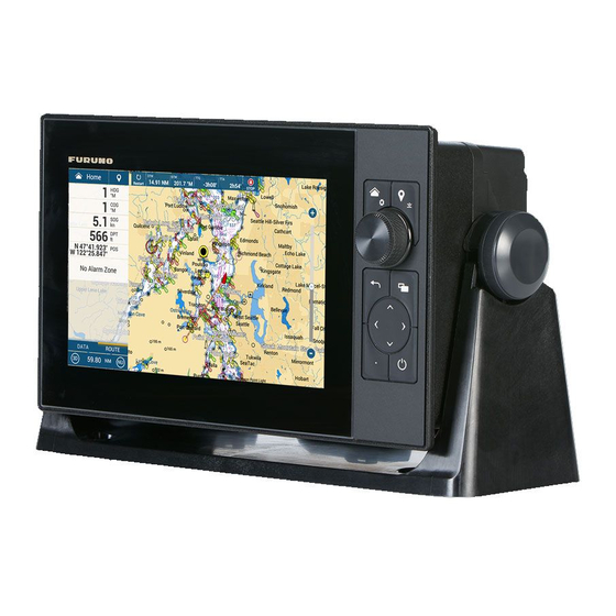
MULTI FUNCTION DISPLAY
TZT9F
Model
SAFETY INSTRUCTIONS ................................................................................................ i
SYSTEM CONFIGURATION ........................................................................................... ii
EQUIPMENT LISTS........................................................................................................ iii
1. MOUNTING..............................................................................................................1-1
1.1 Installation of Multi Function Display..................................................................................1-1
1.2 Installation of Transducers.................................................................................................1-7
2. WIRING....................................................................................................................2-1
2.1 Interface Connections (Rear of Unit) .................................................................................2-1
2.2 Composite Connector ........................................................................................................2-2
2.3 How to Secure and Waterproof Connections.....................................................................2-2
2.4 Power Cable ......................................................................................................................2-3
2.5 MULTI Cable......................................................................................................................2-3
2.6 DRS Radar Sensor Connections .......................................................................................2-4
2.7 Network Connector ............................................................................................................2-4
2.8 CAN bus (NMEA2000 Connector) .....................................................................................2-4
2.9 Transducer (Option)...........................................................................................................2-9
2.10 Example TZT9F System Configurations ............................................................................2-9
3. HOW TO SET UP THE EQUIPMENT......................................................................3-1
3.1 How to Set Time Zone, Time Format and Language.........................................................3-4
3.2 How to Set Units of Measurement .....................................................................................3-6
3.3 Initial Setup ........................................................................................................................3-7
3.4 How to Set Up the Radar .................................................................................................3-13
3.5 How to Set Up the Fish Finder.........................................................................................3-16
3.6 Wireless LAN Setting .......................................................................................................3-21
3.7 Ferry Mode.......................................................................................................................3-22
PACKING LIST(S) ....................................................................................................... A-1
OUTLINE DRAWING(S) .............................................................................................. D-1
INTERCONNECTION DIAGRAM(S) ........................................................................... S-1
www.furuno.com
All brand and product names are trademarks, registered trademarks or service marks of their respective holders.
Advertisement
Table of Contents

Related Manuals for Furuno TZT9F


Summary of Contents for Furuno TZT9F
-
Page 1: Table Of Contents
2.7 Network Connector ......................2-4 2.8 CAN bus (NMEA2000 Connector) ..................2-4 2.9 Transducer (Option)......................2-9 2.10 Example TZT9F System Configurations ................2-9 3. HOW TO SET UP THE EQUIPMENT..............3-1 3.1 How to Set Time Zone, Time Format and Language............3-4 3.2 How to Set Units of Measurement ..................3-6 3.3 Initial Setup ........................3-7... - Page 2 ・FURUNO Authorized Distributor/Dealer 9-52 Ashihara-cho, Nishinomiya, 662-8580, JAPAN A : OCT 2020 Printed in Japan All rights reserved. D : JUN . 06, 2022 Pub. No. IME-45090-D (DAMI ) TZT9F 0 0 0 1 9 7 9 0 7 1 3...
-
Page 3: Safety Instructions
If your vessel is configured with 0.40 m 0.30 m TZT9F an autopilot system, install an autopilot control unit (or emer- gency autopilot stop button) at each helm station, to allow you to disable the autopilot in an emergency. -
Page 4: System Configuration
The basic functions of the hub were verified, however the compatibility of all functions were not checked. FURUNO cannot guarantee proper operation. : FURUNO networks allow a maximum of three HUB-101 units on the same network. : DRS6A-NXT is rated for either 12 V or 24 V DC power supply. -
Page 5: Equipment Lists
EQUIPMENT LISTS Standard supply Name Type Code No. Remarks Multi Function Display TZT9F CP19-02701 001-587-750 Installation Materials CP19-02702 001-587-760 Cable Assembly MJ-A3SPF0019-035C 000-156-058 Accessories FP26-00401 001-175-940 Flush Mounting Tem- C42-02003 001-197-909 plate Operator’s Guide OSE-45120-* 000-197-102-** Installation Manual IME-45090-* 000-197-907-**... - Page 6 EQUIPMENT LISTS Name Type Code No. Remarks Rectifier RU-3423 000-030-443 PR-62 000-013-484 100 VAC 000-013-485 110 VAC 000-013-486 220 VAC 000-013-487 230 VAC RU-1746B-2 000-030-439 Cable Assy. FRU-F12F12-100C 001-560-390 FRU-F12F12-200C 001-560-400 FRU-F7F7-100C 001-560-420 FRU-F7F7-200C 001-560-430 Transducer (for inter- 000-015-204 600 W 520-5PSD nal fish finder) 000-015-212...
- Page 7 • No TD-ID recognition Other compatible transducers (local supply) The transducers (Manufactured by AIRMAR Technology Corporation) listed in the table below are compatible with this equipment. Contact your local FURUNO dealer for purchase. Single Frequency CHIRP (For internal fish finder) Output power...
- Page 8 EQUIPMENT LISTS This page is intentionally left blank.
-
Page 9: Mounting
MOUNTING Installation of Multi Function Display The TZT9F is designed to be mounted in a console or panel, or mounted on a desktop. The installer of this equipment must read and follow the descriptions in this manual. Wrong installation or maintenance can void the warranty. - Page 10 1.1.1 Desktop mounting Your TZT9F is shipped with a bracket for desktop mounting. The following procedure shows how to install the unit on a desktop. 1. Place the unit face-down on a soft/clean surface, then unfasten the knob bolts on either side of the unit.
- Page 11 3. Prepare a cutout in the mounting location using the template (supplied) for the TZT9F. 4. Fasten the wing bolts and the wing nuts of the flush mount fixture so that the pro- tector for screw moves to the flush mount fixture.
- Page 12 1. MOUNTING 5. Connect all cables at the back of the TZT9F. (See section 2.1) 6. Attach flush mount sponges to the bezel of TZT9F. Flush mount sponge 9H (2 pcs.) Flush mount sponge 9V (2 pcs.) Peel off the release paper.
- Page 13 Flush mount fixture is fixed at right angle. Flush mount fixture is warped, wing bolts are tilted. 1.1.3 Retrofit Kit for TZT9F (option) When upgrading to the TZT9F, use the Front Fixing Panel Kit (OP19-25). Type: OP19-25 Code No. 001-587-790 Name Type Code No.
- Page 14 1. MOUNTING 3. Set the F Mount Panel to the TZT9F unit, then using the hex bolts attached to TZT9F, fix the F Mount Panel to the unit. TZT unit TZT unit Hex bolt Hex bolt Frontmount panel 4. Connect necessary cable, referring to chapter 2.
-
Page 15: Installation Of Transducers
1. MOUNTING Installation of Transducers CAUTION Do not cover the transducer with FRP resin. The heat generated when the resin hardens may damage the transducer. CHIRP transduc- ers are especially vulnerable to heat. There are three methods for installing the transducer on the ship (thru-hull mount, in- side the hull and transom mount) and one of those methods is to be selected accord- ing to the structure of the ship. - Page 16 1. MOUNTING 1.2.1 How to mount a transducer through the hull Transducer mounting location The thru-hull mount transducer provides the best performance of all, since the trans- ducer protrudes from the hull and the effect of air bubbles and turbulence near the hull skin is reduced.
- Page 17 1. MOUNTING Installation procedure 1. With the boat hauled out of the water, mark the location chosen for mounting the transducer on the bottom of the hull. 2. If the hull is not level within 15° in any direction, fairing blocks made out of teak should be used between the transducer and hull, both inside and outside, to keep the transducer face parallel with the water line.
- Page 18 1. MOUNTING 1.2.2 How to mount a transducer inside the hull NOTICE This installation method affects the ability to detect the bottom, fish and other objects because the ultrasound pulse is weakened when it passes through the hull. Therefore, refrain from this mounting method for a transducer that supports the RezBoost™...
- Page 19 7. Confirm the available fish finder from the list of available sounders, then tap the appropriate fish finder. For the purpose of this example, the default setting [TZT9F] (internal sounder) is selected as the source. 8. Tap the [<] icon to return to the [Fish Finder] menu.
- Page 20 1. MOUNTING Installation procedure 1. Lightly roughen the transducer face with #100 sandpaper. Also, use the sandpa- per to roughen the inside of the hull where the transducer is to be mounted. Wipe off any sandpaper dust from the face of the transducer. 2.
- Page 21 1. MOUNTING 1.2.3 How to install the transom mount transducer The optional transom mount transducer is very commonly employed, usually on relatively small I/O or outboard boats. Do not use this method on an inboard motor boat because turbulence is created by the propeller ahead of the transducer. DO NOT over-tighten screws, to prevent damage to the transducer.
- Page 22 1. MOUNTING Transducer preparation Before putting your boat in water, wipe the face of the transducer thoroughly with a liquid detergent. This will lessen the time necessary for the transducer to have good contact with the water. Otherwise the time required for complete "saturation" will be lengthened and performance will be reduced.
- Page 23 1. MOUNTING 1.2.4 How to install a triducer DO NOT over-tighten screws, to prevent damage to the transducer. Tools and materials required • Scissors • Masking tape • Safety goggles • Dust mask • Electric drill • Screwdrivers • Drill bit: For bracket holes: 4 mm, #23, or 9/64”...
- Page 24 1. MOUNTING Mount the sensor close to the centerline of your boat. On slower heavier displacement hulls, posi- tioning it farther from the centerline is acceptable. For single drive boat, mount on the star-board side at least 75 mm (3") beyond the swing radius of the propeller, as shown in the right figure.
- Page 25 1. MOUNTING Adjustments 1. Using a straight edge, sight the underside of the sensor relative to the underside of the hull. The stern of the sensor should be 1-3 mm (1/16-1/8”) below the bow of the sensor or parallel to the bottom of the hull. Note: Do not position the bow of the sensor lower than the stern because aeration will occur.
- Page 26 1. MOUNTING How to attach the sensor to the bracket 1. If the retaining cover near the top of the bracket Step 1 Step 2 is closed, open it by depressing the latch and Latch rotating the cover downward. Pivot 2.
-
Page 27: Wiring
WIRING Interface Connections (Rear of Unit) Rear of TZT9F Rear of TZT9F Ground wire (Local supply, IV-8sq.)* Transducer Cable Transducer Cable TO: Ship’s ground Power Cable Power Cable MJ-A3SPF0019-035C MJ-A3SPF0019-035C 3.5 m, supplied) 3.5 m, supplied) TO: Transducer Composite connector... -
Page 28: Composite Connector
2.5 for details. USB port The TZT9F has one USB Ver. 2.0 port which can be used to connect an optional SD card unit or remote control unit, and to be operated from touch device or PC mouse. How to Secure and Waterproof Connections Where the unit is exposed to water spray or moisture, all the connectors and MULTI cable connections to the TZT9F must have at least IPx2 waterproof rating. -
Page 29: Power Cable
2. WIRING Power Cable Connect the power cable (FRU-3P-FF-A002M-000, 2m, supplied) to the connector. When connecting the power supply, connect the positive and negative terminals cor- rectly. Note: Turn off the power at the switchboard before beginning the connection. Ground wire Connect the ground wire (IV-8sq, local supply) to the ground terminal on the rear panel with the crimp terminal. -
Page 30: Drs Radar Sensor Connections
TZT9F Network Connector Like previous NavNet series equipment, the TZT9F may share radar and fish finder images, and other information, across an Ethernet connection. Up to six TZT9F units may be connected to the same network at one time. However, for configurations with one or more TZT2BB included, the maximum number of networked TZT9F units is four. - Page 31 , the TZT9F can display engine information on a dedicated Yamaha engine status display. How to connect the engine The TZT9F connects to the Yamaha engine network via the Yamaha Interface Unit. Arrange the Yamaha Interface Unit through a local Yamaha representative. Yamaha Interface Unit...
- Page 32 /Command Link Plus /Helm Master How to set up the engine display Once the TZT9F detects the Yamaha engine network, the engine can be set up on [Settings]→[Initial Setup]→[YAMAHA ENGINE SETUP]. See section 3.3 for details. 2.8.3 NMEA0183 equipment data input Note: To output NMEA0183 data, see paragraph 2.5.1.
- Page 33 2. WIRING Description 127250 Vessel Heading 127251 Rate of Turn 127257 Attitude 127258 Magnetic Variation 127488 Engine Parameters, Rapid Update 127489 Engine Parameters, Dynamic 127505 Fluid Level 128259 Speed 128267 Water Depth 129025 Position, Rapid Update 129026 COG & SOG, Rapid Update 129029 GNSS Position Data 129033...
- Page 34 The CAN bus output PGN setting (found under the [Initial Setup] menu) is global to the network. Note that only one TZT9F will output CAN bus data on the network at a time: the TZT9F which is powered ON first. If that display is turned OFF, another will take its place to output the data.
-
Page 35: Transducer (Option)
2. WIRING Transducer (Option) The Matching Box MB-1100 is required when connecting a 1kW transducer to TZT9F. See the interconnection diagram for transducer connection. All other transducers are connected to the TZT9F directly. 2.10 Example TZT9F System Configurations Small vessels (internal GPS, internal fish finder, radar) The example below shows a typical configuration for small vessels. - Page 36 CAN bus backbone cable CAN bus CAN bus drop cable HUB-101* drop cable Multi Function Display Multi Function Display Multi Function Display Multi Function Display TZT9F TZT9F TZT9F TZT9F USB Hub* 24 VDC 12 to 24 12 to 24 Remote Control Unit...
-
Page 37: How To Set Up The Equipment
HOW TO SET UP THE EQUIP- MENT This chapter shows you how to set up your system according to the equipment you have connected. Touch control description The touch control depends on the screen type. The basic operations to use during the installation setup are in the following table. - Page 38 3. HOW TO SET UP THE EQUIPMENT Control description Item Function • Short push: Turns the power on. With the unit powered, the [Quick Access] window appears. (Power switch) [Quick Access] window • Toggles radar, fish finder, multibeam sonar, NavPilot between transmit and stand-by.
- Page 39 After reading the message, tap [OK]. 3. Tap the [Home] icon ( ) to show the home screen and display mode settings. TZT9F Home menu 4. Tap [Settings] to open the [Settings] menu. 5. Scroll the menu to show [Initial Setup], then tap [Initial Setup].
-
Page 40: How To Set Time Zone, Time Format And Language
3. HOW TO SET UP THE EQUIPMENT How to use the software keyboard Alphabet software keyboard Numeric software keyboard Description Cursor position is highlighted. Backspace/Delete. Tap to erase one character at a time. Enter button. Tap to complete character input and apply changes. Cursor keys. - Page 41 3. HOW TO SET UP THE EQUIPMENT 9. Tap [Language] to show the [Language] menu. 10. Tap the appropriate language to use. The unit will display a confirmation mes- sage. Tap [OK] to restart the unit and apply the new language settings.This pro- cess takes approximately five minutes to optimize the system for the new language setting.
-
Page 42: How To Set Units Of Measurement
3. HOW TO SET UP THE EQUIPMENT How to Set Units of Measurement 1. Tap the [Home] icon to show the home screen and display mode settings. 2. Tap [Settings] to show the [Settings] menu. 3. Scroll the main menu to display [Units], then tap [Units]. 4. -
Page 43: Initial Setup
3. HOW TO SET UP THE EQUIPMENT Initial Setup This section shows you how to set your system according to the sensors you have connected. Note: Some units are set to metric in this section, actual setting ranges vary depending on the unit of measurement set in the [Units] menu. 1. - Page 44 3. HOW TO SET UP THE EQUIPMENT [HOME] Screen Setup Menu item Description Options (setting range) [Restore Default Set- Click [OK] to restore the [HOME] screen’s default settings. tings] Manual Fuel Management Setup Menu item Description Options (setting range) [Total Fuel Capacity] Enter the total fuel capacity of your 0 to 9,999(L).
- Page 45 Select the source for each data to input to the system. If two or more sources are connected for a data, select one using the pull-down dialog box. The FURUNO products are shown at the upper part of the list. [Sensor List] Show the information for sensors connected to your equipment.
- Page 46 3. HOW TO SET UP THE EQUIPMENT [Initial Setup] menu - [NETWORK SENSOR SETUP] The [NETWORK SENSOR SETUP] section allows you to set up compatible FURUNO NMEA2000 sensors. Calibrations and offsets applied in this menu are also applied to the sensor itself.
- Page 47 IP address for this unit within the network. [Synchronization Log] Shows synchronization with devices connected to the network. [Quick Self Test] Displays various details regarding the TZT9F, radar and fish finder. [Certification Mark] Displays relevant certification for this equipment. [Service] Requires login password.
- Page 48 [Initial Setup] menu - [Engine & Tank Automatic Setup] The TZT9F will automatically detect engines and tanks connected to the same net- work.This is the recommended method for setting up engines and tanks. [Initial Setup] menu - [Engine & Tank Manual Setup] The manual set up method should only be used if the automatic setup did not correctly detect your engines or tanks.
-
Page 49: How To Set Up The Radar
3. HOW TO SET UP THE EQUIPMENT Menu Item Description Options (setting range) [Nickname] Change the nickname for the engine or tank. [Used For Propulsion] Select which engine/tank is used to [OFF], [ON] calculate the distance which may be traveled using the remaining fuel. [ON] uses the engine/tank for calculations, [OFF] ignores the engine/tank. - Page 50 3. HOW TO SET UP THE EQUIPMENT [Radar] menu - [Antenna Position] Menu item Description Options (setting range) [Longitudinal (from bow)] Referring to the figure on the right, [0] m to [999] m enter the radar antenna position- [Lateral (-Port)] [-99] m to [+99] m ing bow-stern (Longitudinal) and Port-side is negative,...
- Page 51 3. HOW TO SET UP THE EQUIPMENT How to align the antenna heading You have mounted the antenna unit facing straight ahead in the direction of the bow. Therefore, a small but conspicuous target dead ahead visually should appear on the heading line (zero degrees).
-
Page 52: How To Set Up The Fish Finder
Select [ON] if you use this equipment in salt water. [OFF], [ON] [Fish Finder Select the connected fish finder.To use the built-in fish [TZT9F], [DFF1/ Source] finder, select [TZT9F], which is the default nickname. The BBDS1], [DFF3], nickname can be changed in [INITIAL SETUP][SEN- [DFF1-UHD], SOR LIST]. [DFF3-UHD] [Preset Frequency Set to change the TX center frequency and CHIRP width. - Page 53 3. HOW TO SET UP THE EQUIPMENT Options Menu item Description (setting range) [Transmission Set the TX power level. See the operator’s manual for de- Internal fish find- Power Mode] tails. er: [Min], [Max] DFF1-UHD: [Off], [Min], [Auto] DFF3-UHD: 0 to [External KP] Select on to synchronize with external sounder’s keying [OFF], [ON]...
- Page 54 • [Manual]: Manually set up the transducer. • [Model]: Select the appropriate transducer model (for FURUNO or AIRMAR transducers). [Model Number] Select the appropriate model number from the list. Note: Only available when [Transducer Setup Type] is set to [Model].
- Page 55 3. HOW TO SET UP THE EQUIPMENT When [Transducer Setup Type] is set to [Model] and connected to DFF3 Menu item Description [High Frequency] Set the frequency (kHz) of the connected high frequency transducer. [Frequency Adjust HF] Fine-tune the high-frequency TX frequency to eliminate interference (set- ting range: -50 to +50).
- Page 56 The [Motion Sensor] menu sets up the motion sensor, which provides for stable dis- play of the seabed, schools of fish, etc. in moderate-to-rough seas. Note 1: For connection of NMEA0183 equipment, ask your FURUNO dealer to set up the motion sensor.
-
Page 57: Wireless Lan Setting
3. HOW TO SET UP THE EQUIPMENT Options Menu item Description (setting range) [Motion Sensor Select the sensor connected to your TZT9F unit. For all [SC30], Type] sensors other than SC-50 and SC-110, select [SC-30]. [SC50_SC110] Note: This menu item is not available when [Fish Finder Source] is set to [TZT9F]. -
Page 58: Ferry Mode
Ferry mode allows the user to change the screen orientation by 180°. Note that all the above heading sensors must support heading offset command from the TZT9F. Both heading sensors and radar sensors must be powered on when the TZT9F sends the command. Both the heading sensor and radar sensor must be powered when the TZT9F sends the heading offset command to them. - Page 64 16/Jun/2021 H.MAKI...
- Page 65 24 months from installation date provided the work is done by Furuno U.S.A., Inc. or an AUTHORIZED Furuno dealer during normal shop hours and within a radius of 50 miles of the shop location.
- Page 66 When a claim is made, FURUNO has a right to choose whether with other electronic devices. The imported product may also be to repair the product or replace it.
Need help?
Do you have a question about the TZT9F and is the answer not in the manual?
Questions and answers
Where is the usb port connection n the tzt9f display