Advertisement
Quick Links
Advertisement
Chapters
Troubleshooting

Subscribe to Our Youtube Channel
Related Manuals for Canon iR C1020 Series


Summary of Contents for Canon iR C1020 Series
- Page 1 Service Manual iR C1020 Series iR C1021i Sep 8 2008...
- Page 3 Canon will release technical information as the need arises. In the event of major changes in the contents of this manual over a long or short period, Canon will issue a new edition of this manual.
- Page 4 Introduction Symbols Used This documentation uses the following symbols to indicate special information: Symbol Description Indicates an item of a non-specific nature, possibly classified as Note, Caution, or Warning. Indicates an item requiring care to avoid electric shocks. Indicates an item requiring care to avoid combustion (fire). Indicates an item prohibiting disassembly to avoid electric shocks or problems.
- Page 5 Introduction The following rules apply throughout this Service Manual: 1. Each chapter contains sections explaining the purpose of specific functions and the relationship between electrical and mechanical systems with refer- ence to the timing of operation. In the diagrams, represents the path of mechanical drive; where a signal name accompanies the symbol , the arrow indicates the direction of the electric signal.
-
Page 7: Table Of Contents
Contents Contents Chapter 1 Introduction 1.1 System Construction ..........................1- 1 1.1.1 System Configuration of Pickup/Delivery Options ....................1- 1 1.1.2 System Configuration of Print/Send Options ......................1- 2 1.1.3 Functions of Print/Send Options..........................1- 2 1.2 Product Specifications ..........................1- 3 1.2.1 Names of Parts................................ - Page 8 Contents 2.2.6 Points to Note When Turning OFF Host Machine....................2- 5 2.2.7 Connecting Cables..............................2- 5 2.2.8 Auto Gradation Adjustment............................2- 6 2.2.9 Operation when moving the host machine.......................2- 6 2.3 Checking the Connection to the Network ....................2- 6 2.3.1 Setting Up the Network ............................2- 6 2.3.2 Procedure for Ping Operation ..........................2- 6 2.3.3 Checking with Remote Host Address ........................2- 7 2.3.4 Troubleshooting Network Connection........................2- 7...
- Page 9 Contents 4.4 Image Data Flow ............................4- 9 4.4.1 Flow of Image Data According to Copy Functions ....................4- 9 4.4.2 Flow of Image Data for the SEND Function ......................4- 10 4.4.3 Flow of Image Data for the Fax Transmission....................... 4- 10 4.4.4 Flow of Image Data for the Fax Reception Function .....................
- Page 10 Contents 6.4.3.1 Removing the ADF Pickup Roller ............................6- 10 6.4.4 Separation Roller ..............................6- 11 6.4.4.1 Removing the ADF Separation Roller............................ 6- 11 6.4.5 Pick-up Motor.................................6- 12 6.4.5.1 Before Removing the ADF Pickup Motor ..........................6- 12 6.4.5.2 Removing the ADF Pickup Motor............................6- 12 6.4.6 Pick-up Solenoid ..............................6- 13 6.4.6.1 Before Removing the ADF Pickup Solenoid ..........................
- Page 11 Contents 8.4.4 Transfer Roller Engagement/disengagement Control ................... 8- 21 8.5 Parts Replacement Procedure .........................8- 25 8.5.1 Drum Motor................................8- 25 8.5.1.1 Before Removing the Drum Motor ............................8- 25 8.5.1.2 Removing the Drum Motor..............................8- 25 8.5.2 Main Drive Unit ..............................8- 25 8.5.2.1 Before Removing the Main Drive Unit............................
- Page 12 Contents 9.5 Parts Replacement Procedure ......................... 9- 18 9.5.1 Pickup Feed Unit..............................9- 18 9.5.1.1 Before Removing the Pickup Feed Unit..........................9- 18 9.5.1.2 Removing the Pickup Feed Unit ............................9- 18 9.5.2 Cassette Pickup Roller............................9- 19 9.5.2.1 Before Removing the Cassette Pickup Roller........................9- 19 9.5.2.2 Removing the Cassette Pickup Roller ...........................
- Page 13 Contents 10.4.4 Fixing Motor ............................... 10- 12 10.4.4.1 Before Removing the Fixing Motor............................. 10- 12 10.4.4.2 Removing the Fixing Motor ..............................10- 12 Chapter 11 External and Controls 11.1 DC Controller ............................11- 1 11.1.1 Overview................................11- 1 11.1.2 Operation of Each Block ............................11- 2 11.1.3 Fan/Motor Control..............................
- Page 14 Contents 11.5.11 Operation Panel Unit ............................11- 20 11.5.11.1 Removing the Control Panel Unit ............................. 11- 20 11.5.11.2 Procedure after Replacing the Control Panel........................11- 21 11.5.12 NCU Board ...............................11- 21 11.5.12.1 Before Removing the NCU PCB ............................11- 21 11.5.12.2 Removing the NCU PCB ..............................11- 21 11.5.13 DC Controller PCB ............................11- 21 11.5.13.1 Before Removing the DC Controller PCB ........................
- Page 15 Contents 14.3.2 Procedure after Replacing the Main Controller PCB ................... 14- 1 14.3.3 Procedure after Clearing RAM Data ........................14- 1 14.3.4 Procedure after Replacing the Control Panel ...................... 14- 2 14.4 ADF.................................14- 2 14.4.1 Outline ................................. 14- 2 14.4.1.1 Procedure after Replacing the ADF Unit..........................14- 2 Chapter 15 Correcting Faulty Images 15.1 Initial Checkup ............................15- 1 15.1.1 Initial Check .................................
- Page 16 Contents 17.2.4 Image error................................17- 3 Chapter 18 Service Mode 18.1 Outline ..............................18- 1 18.1.1 Service Mode Configuration..........................18- 1 18.1.2 Entering/Selecting Service Mode .........................18- 3 18.1.3 Exiting Service Mode ............................18- 3 18.1.4 Service Mode Backup ............................18- 3 18.1.5 Service Mode Screen Operation ..........................18- 4 18.2 COPIER ..............................
- Page 17 Contents 19.3 Downloading System Software .......................19- 3 19.3.1 Downloading the System Software........................19- 3 19.3.1.1 Downloading Procedure............................... 19- 3 Chapter 20 Service Tools 20.1 Service Tools ............................20- 1 20.1.1 Special Tools ............................... 20- 1 20.1.2 Standard Tools ..............................20- 2 20.1.3 Solvent/Oil List..............................
- Page 18 Contents...
-
Page 19: Chapter 1 Introduction
Chapter 1 Introduction... - Page 21 Contents Contents 1.1 System Construction ..............................1-1 1.1.1 System Configuration of Pickup/Delivery Options ........................1-1 1.1.2 System Configuration of Print/Send Options ..........................1-2 1.1.3 Functions of Print/Send Options ..............................1-2 1.2 Product Specifications..............................1-3 1.2.1 Names of Parts ..................................... 1-3 1.2.1.1 External View........................................1-3 1.2.1.2 Cross Section........................................1-4 1.2.2 Using the Machine ..................................
-
Page 23: System Construction
Chapter 1 1.1 System Construction 1.1.1 System Configuration of Pickup/Delivery Options 0019-4882 F-1-1 Cassette Feeding Unit-AB1... -
Page 24: System Configuration Of Print/Send Options
Chapter 1 1.1.2 System Configuration of Print/Send Options 0019-5668 [5]-[7] F-1-2 Super G3 Fax Board-AB1 HANDSET-J1 *1 Card Reader-E1 System Upgrade RAM-A1 *2 Card Reader Attachment Kit-F1 Color Send Kit-W1 *2 PCL Printer Kit-Y1 *3 Barcode Printing Kit-C1 *4 For all excluding Europe, KR For North America, AUS, KR only For all excluding JP, Europe Except Japan... -
Page 25: Product Specifications
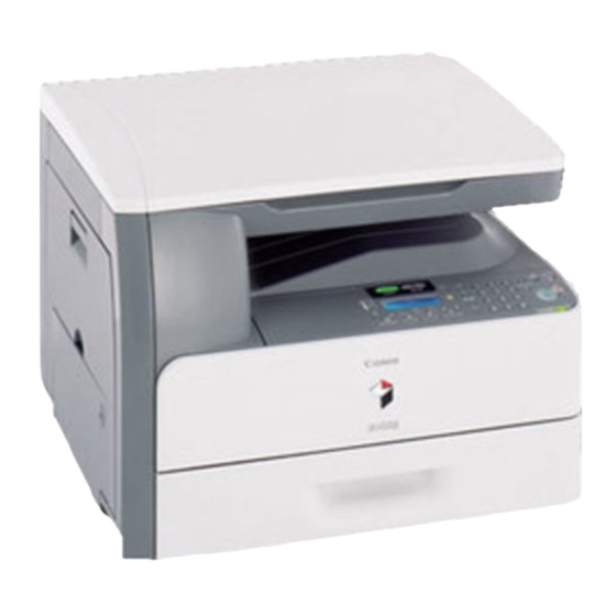
Chapter 1 1.2 Product Specifications 1.2.1 Names of Parts 1.2.1.1 External View 0019-4884 <Front> [10] [11] [12] [13] [14] [15] [16] [17] [18] F-1-3 Feeder Original Supply Tray Control Panel Cassette 1 Manual feed tray Front Cover Delivery tray Reader Unit Scanning Area [10] Platen Glass... -
Page 26: Cross Section
Chapter 1 1.2.1.2 Cross Section 0019-4885 <ADF / Reader> F-1-5 ADF unit ADF pickup roller ADF delivery roller Reader unit Platen glass CCD unit <Main Body> [14] [13] [12] [11] [10] F-1-6 Reverse unit Delivery unit Delivery roller Fixing unit ETB unit Photosensitive drum Manual pickup roller... -
Page 27: Using The Machine
Chapter 1 1.2.2 Using the Machine 1.2.2.1 Turning on the Power Switch 0019-4889 The machine is equipped with the "main power switch" and "control panel power switch". - Main power switch: Used to turns OFF/ON the machine. - Control panel power switch: Used to enter the power save mode/low power mode/sleep mode. -
Page 28: Control Panel
Chapter 1 1.2.2.2 Control Panel 0020-6125 [1] [2] [3] [25] [24] [23] [22] [21] [20] [19] [18] [17] [16] [15] [14] [13] [12] [11] [10] F-1-8 Custom key 2 Custom key 1 Main Menu key Display Numeric keys Power switch (sub power supply) USB slot Volume control dial Clear key... -
Page 29: User Mode Items
Chapter 1 1.2.3 User Mode Items 1.2.3.1 Overview 0020-0865 The following are the user mode setting items. MEMO: - Drawer 2 is an option cassette. - Some setting items are displayed by pressing the left/right Any key. Perform operations by referring to the functions of the left/right Any key displayed at the bottom of the screen. -
Page 30: Common Settings
Chapter 1 1.2.3.4 Common Settings 0019-4898 *: default settings *1: Only when the Cassette Feeding Unit-AB1 is attached. *4: Only when the appropriate optional equipment is attached. T-1-4 Common Settings Item Settings Initial Function Settings Select Initial Function Main Menu *, Copy, Scan to Send, Scan to Store, Direct Print Set System Monitor to Def. -
Page 31: Communications Settings *3
Chapter 1 1.2.3.5 Communications Settings *3 0019-4899 Common Settings *: default settings **: China only *3: Only when the Super G3 FAX Board is attached. *4: Only when the appropriate optional equipment is attached. T-1-5 Communications Settings*3 > Common Settings Item Settings Send Function Settings... - Page 32 Chapter 1 Fax Settings *: default settings *3: Only when the Super G3 FAX Board is attached. *4: only for Japan, China, KR *5: except AUS *6: except Singapore *7: only U.S.A. *8: only for AUS *9: The maximum differs depending on the destination. T-1-6 Communications Settings *3 >...
-
Page 33: Address Book Settings
Chapter 1 1.2.3.6 Address Book Settings 0019-4900 *: default settings *4: Only when the appropriate optional equipment is attached. T-1-7 Address Book Settings Item Settings Register Address *4 Register New Register Name Max 16 characters Destination Registration Max. 120 characters Option ECM TX OFF/ON*... - Page 34 Chapter 1 T-1-8 Address Book Settings Item Settings Register One-touch *4 (Select the number of available one-touch dial.) Register Name Max. 16 characters Register One-Touch Name Max. 12 characters Destination Registration Max. 120 characters ECM TX OFF/ON* Sending Speed 33600bps *, 14400bps, 9600bps, 4800bps Long Distance Domestic *, Long Distance (1), Long Distance (2), Long Distance (3) E-Mail...
-
Page 35: Printer Settings
Chapter 1 1.2.3.7 Printer Settings 0020-9811 *: default settings *2: Only when the PCL Printer Kit is attached. *3: Only when the Barcode Printing Kit is attached. T-1-9 Printer Settings Item Settings Number of Copies 1 to 999 Copies 1* 2-Sided 1-Sided *, 2-Sided Paper Feed... - Page 36 Chapter 1 T-1-10 Printer Settings Item Settings PCL Settings*2 Paper Save OFF* / ON Orientation Portrait *, Landscape Font Number (0 to 91) 0* 4.00 to 999.75 point Width 0.25 point (12*) Character Size point (4.00 to 999.75) 12.00* Width 0.25point No.
-
Page 37: Timer Settings
Chapter 1 1.2.3.8 Timer Settings 0019-4902 ***: For all excluding Japan, Asia The following are the items for timer settings. 1. Month 2. Week (1st/2nd/3rd/4th/End) 3. Day of week 4. Time(00 - 23): No setting by minutes Default: No setting T-1-11 Timer Settings Item... -
Page 38: Adjustment/Cleaning
Chapter 1 1.2.3.9 Adjustment/Cleaning 0019-4903 *: default settings *1: default: not displayed(IR C1022i / IR C1021I / iRC 1021i / IRC 1022 / iRC 1021 for North America, Europe, and Australia), displayed(Others) T-1-12 Adjustment/Cleaning Item Settings Full Correction (Test Print 1->Start reading x 3 times) Auto Gradation Correction Quick Correction (No test print->... -
Page 39: System Management Set
Chapter 1 1.2.3.11 System Management Set. 0019-4905 *: default settings *4: Only when the appropriate optional equipment is attached. System Manager Info. Set. T-1-15 System Management Set. > System Manager Info. Set. Item Settings System Mgmt. Dept. ID Max 7 digits System Mgmt. - Page 40 Chapter 1 User ID Management T-1-18 System Management Set. > User ID Management Item Settings (User ID Management) OFF*/ON Card ID Management T-1-19 System Management Set. > Card ID Management Item Settings Register ID/Password Dept. ID Max. 8 characters Password Max.
- Page 41 Primary DNS Server IP Address (0.0.0.0*) Secondary DN Server IP Address (0.0.0.0*) DNS Host/Domain Name Host Name Max. 47 characters (*: Canon****** (“******”represents the last six digits of a MAC address)) Domain Name Max. 47 characters DNS Dynamic Update Settings OFF*/ON 1-19...
- Page 42 DNS Host/Domain Name Use Same Host Name/Domain Name as OFF*/ON IPv4 Host Name Max. 47 characters (*: Canon****** (“******”represents the last six digits of a MAC address)) Domain Name Max. 47 characters DNS Dynamic Update Set. Use DNS Dynamic Update OFF*/ON Manual Address Regist.
- Page 43 Chapter 1 T-1-22 System Management Set. > Network Settings Item Settings TCP/IP Settings WINS Configuration *4 WINS Resolution OFF*/ON WINS Server Address IP Address (Only when WINS resolution is implemented) (0.0.0.0) * LPD Print Settings OFF/ON* RAW Print Settings OFF/ON* Use Bidirectional OFF*/ON WSD Print Settings...
- Page 44 Enter IP address in the case that a DNS server is not provided. In the case that an IP address for the DNS server is registered, enter a name that the DNS server can understand. Ex.: mail_server.ccm.canon.co.jp Account for sending E mail, I-Fax...
- Page 45 Chapter 1 Forwarding Settings *4 T-1-25 System Management Set. > Forwarding Settings *4 Item Settings Forwarding Condition Setting All, Fax, I-Fax *4 Switch Forwarding On / Off OFF*/ON Register Fowarding Cond. Name Max. 50 characters Forwarding Condition Setting Fax *, I-Fax Forwarding Condition Destination: Pull-down (disregard *, Does Not Exist, equals, differs from, begins with, ends with, contains, does not...
- Page 46 Chapter 1 Auto Online/Offline T-1-29 System Management Set. > Auto Online/Offline Item Settings Auto Online OFF*/ON Auto Offline OFF*/ON Job Log Display T-1-30 System Management Set. > Job Log Display Item Settings (Job Log Display) OFF/ON* Memory Media Store Log T-1-31 System Management Set.
-
Page 47: Maintenance By The User
Chapter 1 1.2.4 Maintenance by the User 1.2.4.1 Cleaning 0019-5678 If the original is not copied clearly, clean the machine. For high-quality printouts, we recommend cleaning the machine once or twice a month. - Do not use alcohol, benzene, paint thinner, or other solvents for cleaning. Doing so may result in damage to the plastic parts. - Do not use tissue paper, paper towels, or similar materials for cleaning;... - Page 48 Chapter 1 F-1-12 The display returns to the Adjustment/Cleaning screen. MEMO: - Discard the cleaning sheet after use. - The cleaning process cannot be canceled. Please wait until it is completed. 6) Press (Main Menu) to return to the Main Menu screen. Scanning Area Keep the scanning area clean to avoid dirty copies or faxes to be sent.
- Page 49 Chapter 1 1) Press (Main Menu). 2) Press the right Any key to select <Additional Func>. F-1-16 3) Use [ ], [ ], or (Scroll Wheel) to select <Adjustment/Cleaning>, then press [OK]. F-1-17 4) Use [ ], [ ], or (Scroll Wheel) to select <Feeder Cleaning>, then press [OK]. F-1-18 5) Place 10 sheets of blank paper into the feeder.
-
Page 50: Safety
Chapter 1 1.2.5 Safety 1.2.5.1 Points to note at disassembly/assembly 0019-4906 Make sure to follow the instruction below at disassembly/assembly. 1. At disassembly/assembly, be sure to unplug the power plug for safety reason. 2. At assembly, execute the operation in the reverse order of disassembly procedure. 3. -
Page 51: Safety Of Toner
Chapter 1 1.2.5.5 Safety of Toner 0018-9079 About Toner The machine’s toner is a non-toxic material made of plastic, iron, and small amounts of dye. Do not throw toner into fire. It may cause explosion. Toner on Clothing or Skin 1. -
Page 52: Product Specifications
Chapter 1 1.2.6 Product Specifications 1.2.6.1 Main Body Specifications 0019-4951 Copyboard Fixed copyboard Body Desktop Light source type Cold-cathode tube Lens type Fixed focal length lens Photosensitive medium OPC drum (24 mm dia) Image reading method Exposure method 2-polygon 4-laser (2-beam/laser) Charging method Roller charging Development method... -
Page 53: Adf Specifications
Chapter 1 Multifeeder paper size LTR, LGL, STMT, EXEC, FLSC, OFI, B-OFI, M-OFI, G-LTR, G-LGL, A4, A5, B5, Custom Size, COM10, Monarch, DL, ISO-C5, ISO-B5 Cassette paper type Plain, Recycled Paper, Color, Bond, Heavy, Rough Multifeeder tray paper type Plain, Recycled Paper, Color, Bond, Heavy, Rough, Transparencies, Labels Cassette capacity Paper cassette: 250 sheets Cassette Feeding Unit-AB1 (optional): 500... -
Page 54: Fax Specifications
Chapter 1 1.2.6.3 FAX Specifications 0020-0877 Applicable lines Public Switched Telephone Network (PSTN) * PSTN currently supports the modem speed of up to 28.8Kbps. It, however, differs depending on the telephone line condition. Number of lines connected: 1 Transmission method Modulation method Image modulation: V.34/V.17/V.29/V.27ter Transmission procedure: V.21... -
Page 55: Function List
Chapter 1 1.2.7 Function List 1.2.7.1 Print Speed 0019-4886 First copy time The following standard is defined with "35 seconds" after printing 90 sheets of A4-size plain paper in the mode of "1 vs. multiple copies" *1 at copyboard reading. (Unit: second) T-1-38 Mode/Pickup position... -
Page 56: Paper Type
Chapter 1 1.2.7.2 Paper Type 0020-5103 Paper Type Supported paper types are shown below: A: available -: not available T-1-40 Type Weight Cassette/ Manual feed tray Optional cassette Plain From 19 to 24 lb (70 to 90 g/m2) Plain H From 20 to 28 lb (75 to 105 g/m2) Color From 19 to 24 lb (70 to 90 g/m2) -
Page 57: Chapter 2 Installation
Chapter 2 Installation... - Page 59 Contents Contents 2.1 Making Pre-Checks................................2-1 2.1.1 Checking Installation Environment ............................. 2-1 2.1.2 Points to Note Before Installation..............................2-1 2.1.3 Checking Contents ..................................2-1 2.2 Unpacking and Installation ............................2-3 2.2.1 Unpacking ....................................2-3 2.2.2 Installation....................................2-3 2.2.3 Installing Others................................... 2-4 2.2.4 Securing Product ..................................2-5 2.2.5 Cassette Settings ..................................
-
Page 61: Making Pre-Checks
Chapter 2 2.1 Making Pre-Checks 2.1.1 Checking Installation Environment 0019-0625 The followings are the condition for installation environment. It is better to see the planned location of installation before carrying the machine in the user site. 1) Installation environment must be with in the following range. Avoid the close location to the faucet, water heater, humidifier or refrigerator. Assured range of operation/image: temperature 10.0 to 30.0 deg C, humidity 20 to 80% 2) Avoid fire, dusty place and the location where ammonia gas is generated. - Page 62 Chapter 2 F-2-2 Power code 1 pc. Main power supply label 1 pc. [3]*1 Customize Label 1 pc. Copy Inhibit Label 1 pc. *1 Since users will use this label, make sure to give it to users.
-
Page 63: Unpacking And Installation
Chapter 2 Refer to the following for Guides / CDs. T-2-1 iR C1021i Starter Guide User Software CD Manual CD PCL User Software Yes: Included 2.2 Unpacking and Installation 2.2.1 Unpacking 0019-0633 MEMO: When installing the Cassette Feeding Unit, put the host machine on the Cassette Feeding Unit. -
Page 64: Installing Others
Chapter 2 F-2-10 7) Hold the grip [A] of the Bk toner cartridge [1] and install it in the direction of the arrow. F-2-7 4) Hold the Bk toner cartridge [1] as below with both hands and shake it 5 to 6 times in the direction of the arrow to even the toner. -
Page 65: Securing Product
Chapter 2 F-2-15 F-2-13 2) Pick the unlock lever [1] of the paper guide and adjust the paper guide [2] to the required paper size. 2.2.4 Securing Product 0019-0665 <When Cassette Feeding Unit is installed> 1) Move the host machine in the installation location and fix the 4 casters [1] of Cassette Feeding Unit with the 4 fixing levers [2]. -
Page 66: Auto Gradation Adjustment
Chapter 2 2.2.8 Auto Gradation Adjustment 0019-0673 Make sure to set a test print correctly. If a test print cannot be read correctly, the adjustments of gradation, density and color cannot be performed appropriately. 1) Open the feeder. 2) Clean the copyboard glass of the host machine. 3) Set A4 or LTR paper on the cassette. -
Page 67: Checking With Remote Host Address
Chapter 2 2.3.3 Checking with Remote Host Address 0019-0682 MEMO: You can check whether the connection to the network is successful or failed by executing Ping with the remote host address. Remote host address: the IP address of the PC terminal connecting/operating with the TCP/IP network environment that connects the host machine. -
Page 68: Installing The Card Reader
Chapter 2 2.5 Installing the Card Reader 2.5.1 Notice At Installation 0019-8625 Installation of this equipment needs 'Card Reader Attachment Kit-F1'. 2.5.2 Checking the Contents 0019-8626 < Card Reader-E1 > F-2-20 2) Install the card reader [1]. - 2 embosses [2] - 1 screw (TP;... -
Page 69: Card Id Registration
Chapter 2 2.5.5 Card ID Registration 0019-8712 Be sure to enter the card number to use in service mode of the host machine after installing the Card Reader. If the number is not entered, the card is not recognized when being inserted. 1) Connect the power plug to the power outlet and turn on the main power switch. -
Page 70: Installation Procedure In The Imageware Accounting Manager (Hereinafter Referred To Iwam) Environment
Chapter 2 2.6.3 Turning OFF the Power of the Host Machine 2.5.6 Installation Procedure in the imageWARE 0020-0538 1) Turn OFF the main power. Accounting Manager (hereinafter referred to iWAM) 2) Remove the power plug (for outlet). Environment 2.6.4 Installation Procedure 0020-3780 1) Select "ON"... -
Page 71: Installing The Memory
Chapter 2 F-2-29 5) Install the 3 wire saddles [1] and secure the route cord part [2] of the hand set with the 3 wire saddles [1]. F-2-31 7) Turn on the main power switch. 8) Check that you can hear the dial tone through the handset. 2.7 Installing the Memory 2.7.1 Checking the Contents 0019-6871... -
Page 72: Checking After Memory Expansion
Chapter 2 F-2-33 F-2-36 2) Remove the face plate [1]. 5) Install the face plate and the cover plate of the rear cover. - 1 screw [2] 6) Insert the power plug into the power outlet. 7) Turn on the main power switch. 2.7.5 Checking After Memory Expansion 0020-1947 1) Enter service mode and output the spec report. -
Page 73: Chapter 3 Basic Operation
Chapter 3 Basic Operation... - Page 75 Contents Contents 3.1 Construction ...................................3-1 3.1.1 Functional Configuration ................................3-1 3.1.2 Connecting the Main PCBs................................3-2 3.2 Basic Sequence ................................3-3 3.2.1 Basic Sequence of Operation ............................... 3-3 3.2.2 Power-On Sequence..................................3-4...
-
Page 77: Construction
Chapter 3 3.1 Construction 3.1.1 Functional Configuration 0019-5071 This machine's functions are divided into 8 blocks. Original feed system Main controller Original exposure system Laser exposure system Image formation system External/auxiliary control system Pickup/feed system Fixing system F-3-1... -
Page 78: Connecting The Main Pcbs
Chapter 3 3.1.2 Connecting the Main PCBs 0019-9009 PCB8 J3004 J3012 J3013 J3016 J1004 J1006 J8125 J8129 J801 J201 J8120 PCB14 J209 J1022 J6028 PCB9 J801 J202 PCB2 J8113 J6151 J8502 J406 J1024 PCB13 PCB11 PCB12 J6101 J8501 J9102 J401 J1023 J8103 J204A... -
Page 79: Basic Sequence
Chapter 3 3.2 Basic Sequence 3.2.1 Basic Sequence of Operation 0019-5072 The operational sequence of a printer is controlled by the microcomputer (CPU) on the DC controller. The purposes of each period, from power-ON until the inverter motor stops after the completion of printing, are listed below. T-3-1 Operation Interval... -
Page 80: Power-On Sequence
Chapter 3 3.2.2 Power-On Sequence 0019-5073 Power-on sequence is to reset the machine's status and to check that there is no JAM or failure. The sequences from power-ON until the stand-by status are as below. Power-ON Initialize CPU Initialize ASIC Start-up fans Video interface communication start Internal communication start... -
Page 81: Chapter 4 Main Controller
Chapter 4 Main Controller... - Page 83 Contents Contents 4.1 Overview/Configuration ..............................4-1 4.1.1 Overview...................................... 4-1 4.1.2 Configurations/functions................................4-2 4.2 Set-Up Sequence ................................4-4 4.2.1 Overview...................................... 4-4 4.2.2 Startup Sequence..................................4-5 4.3 Image Processing ................................4-6 4.3.1 Overview of the Image Flow ............................... 4-6 4.3.2 Construction of the Image Processing Module ..........................4-6 4.3.3 Reader Unit Input Image Processing ............................
-
Page 85: Overview/Configuration
Chapter 4 4.1 Overview/Configuration 4.1.1 Overview 0020-0204 The machine's main controller mainly consists of the following parts. T-4-1 PCB Name Function Main controller PCB System control, memory control, image processing control, interface control Extended RAM DIMM Memory for image storage Memory for work (image processing and data analysis, etc.) F-4-1 [A] Reader unit... -
Page 86: Configurations/Functions
Chapter 4 4.1.2 Configurations/functions 0019-8989 J8131 J8120 J8121 J8125 J8140 J8113 J8129 J8117 J8103 J8114 J8133 J8109 IC13 J8118 J8119 J8112 J8110 J8132 IC28 J8104 IC27 IC24 J8111 IC30 IC31 IC33 IC32 J8106 IC34 IC35 IC37 IC42 J8134 J8123 IC38 BAT1 J8126 J8124... - Page 87 Chapter 4 T-4-3 Jack No. Function Connect to J8101 Serial interface for debug J8102 Not implemented J8103 USB on a control panel, Connect to a media card reader Control panel relay PCB J8104 USB device connector USB device J8106 RAM DIMM connector RAM DIMM for expansion J8109 SRAM connector for debug...
-
Page 88: Set-Up Sequence
Chapter 4 4.2 Set-Up Sequence 4.2.1 Overview 0020-8294 The system software controlling the machine is stored in the main program ROM in the main controller PCB. At the time of startup, the CPU reads the system software from the main program ROM into the main memory (DDR-SDRAM) according to the boot program in the BOOT ROM. -
Page 89: Startup Sequence
Chapter 4 4.2.2 Startup Sequence 0020-8295 1. Boot Program Executed by the CPU in the main controller PCB when the main power switch is turned on. Check the status of the image memory (DDR-SDRAM). Load the control program from the main program ROM to the memory if the status is normal. Display an error code when a fault is detected. -
Page 90: Image Processing
Chapter 4 4.3 Image Processing 4.3.1 Overview of the Image Flow 0020-0950 Other iR machine Original Copy Scan -SEND -FAX -PullScan -E-Mail Image data -PDL Print Print output F-4-5 4.3.2 Construction of the Image Processing Module 0020-0951 Image processing is mainly executed by the main controller PCB. The configuration of related modules is shown below. -
Page 91: Reader Unit Input Image Processing
Chapter 4 4.3.3 Reader Unit Input Image Processing 0020-0952 The main controller PCB performs image processing to the image data read by the CCD. Reader unit Main controller PCB Enlargement/reduction Edge emphasis To compression/expansion/editing block F-4-7 4.3.4 Compression/ Extesion/ Editing Block 0020-0953 In this processing, compression/extension/editing are performed. -
Page 92: Printer Unit Output Image Processing
Chapter 4 4.3.5 Printer unit Output Image Processing 0020-0954 The main controller PCB performs image processing to perform printing to the image data received from the reader unit. Main controller PCB Compression/expansion/editing block -intensify-to-density conversion -density adjustment (F adjustment) -gamma correction Binary processing (error diffusion) Binary density conversion Enlargement/reduction... -
Page 93: Image Data Flow
Chapter 4 4.4 Image Data Flow 4.4.1 Flow of Image Data According to Copy Functions 0020-0955 Reader unit Main controller PCB Image processing block for reader unit Data rotation Data compression Data expansion Image processing block for printer unit (row data) DC controller PCB F-4-10... -
Page 94: Flow Of Image Data For The Send Function
Chapter 4 4.4.2 Flow of Image Data for the SEND Function 0020-0956 Reader unit Main controller PCB Image processing block for reader unit Data expansion USB1.1 Data rotation Resolution conversion Ethernet port (compression data) To network F-4-11 4.4.3 Flow of Image Data for the Fax Transmission 0020-0957 Reader unit Main controller PCB... -
Page 95: Flow Of Image Data For The Fax Reception Function
Chapter 4 4.4.4 Flow of Image Data for the Fax Reception Function 0020-0958 Modem board Main controller PCB Image processing block for fax Data rotation Data compression Data expansion Image processing block for printer unit DC controller PCB F-4-13 4.4.5 Flow of Image Data for the PDL Function 0020-0959 Ethernet Main controller PCB... -
Page 96: Parts Replacement Procedure
Chapter 4 4.5 Parts Replacement Procedure 4.5.1 Main Controller PCB 4.5.1.1 Before Removing the Main Controller PCB 0020-3324 1) Remove the ETB unit.(page 8-30)Reference [Removing the ETB Unit] 2) Remove the rear cover unit.(page 11-11)Reference [Removing the Rear Cover Unit] 3) Remove the left cover.(page 11-13)Reference [Removing the Left Cov- 4) Remove the right cover.(page 11-11)Reference [Removing the Right Cover]... -
Page 97: Chapter 5 Original Exposure System
Chapter 5 Original Exposure System... - Page 99 Contents Contents 5.1 Basic Construction .................................5-1 5.1.1 Overview...................................... 5-1 5.1.2 Major Components..................................5-1 5.2 Basic Sequence ................................5-3 5.2.1 Basic Sequence of Operation at Power-on........................... 5-3 5.2.2 Basic Sequence of Operation in Response to a Press on the Start Key (book) ................5-4 5.3 Various Control................................5-5 5.3.1 Lamp Control ....................................
-
Page 101: Basic Construction
Chapter 5 5.1 Basic Construction 5.1.1 Overview 0019-8961 T-5-1 Item Function/Method Lamp Cold-cathode tube Document scan Book mode: Scanning by movement of the CCD unit ADF: Scanning in stream reading mode with CCD unit fixed Reading resolution 600 dpi x 600 dpi Gradation 256 gradation Productivity (ADF) - Page 102 Chapter 5 Constitution of the CCD unit The light illuminated from the 2 document lamps (LAMP1, 2) is reflected to the original and reaches to the CCD via the 4 mirrors and the lenses. F-5-2 CCD PCB (PCB11) Inverter PCB (PCB12) Document lamps (LAMP1, 2) CCD unit Mirrors...
-
Page 103: Basic Sequence
Chapter 5 5.2 Basic Sequence 5.2.1 Basic Sequence of Operation at Power-on 0019-8965 HP shift Pre-scan operation *1 HP shift WAIT Reader motor (M12) Document lamp (LAMP1,2) Reader HP sensor (SR717) End position of pre-scan : Motor forward : Motor reverse : Document lamp ON : Reader HP sensor ON F-5-3... -
Page 104: Basic Sequence Of Operation In Response To A Press On The Start Key (Book)
Chapter 5 5.2.2 Basic Sequence of Operation in Response to a Press on the Start Key (book) 0019-8966 Move shading correction *2 HP shift Book Position shift Gain correction *1 Scan movement HP shift Start key ON STBY SREADY Reader motor (M12) Document lamp (LAMP1,2) -
Page 105: Various Control
Chapter 5 5.3 Various Control 5.3.1 Lamp Control 5.3.1.1 Overview 0020-0963 Advance lamp activation control It takes 9 to 25 sec (which varies depending on the surrounding temperature) from when the cold-cathode tube lamp, which is used as a document lamp, is activated to when the light intensity reaches the target intensity. -
Page 106: Detecting The Size Of Originals
Chapter 5 1 %. 5.3.3 Detecting the Size of Originals 5.3.3.1 Overview 0019-8968 The machine does not perform document size detection. (The machine is not equipped with the document size sensor.) The machine performs reading in the size specified on the control panel when reading the document. -
Page 107: Dirt Sensor Control
Chapter 5 5.3.4 Dirt Sensor Control 5.3.4.1 Overview 0019-8969 The machine performs dust detection control when stream reading is performed on the ADF. When dust is adhered to the scanning glass surface, the correction is made to remove the dust from the scanned image. Dust detection control is executed for all documents for which stream reading is performed regardless of the mode. -
Page 108: Parts Replacement Procedure
Chapter 5 5.4 Parts Replacement Procedure 5.4.1 ADF Unit + Reader Unit 5.4.1.1 Before Removing the ADF Unit + Reader Unit 0020-0717 1) Remove the rear cover unit.(page 11-11)Reference [Removing the Rear Cover Unit] 5.4.1.2 Removing the ADF Unit + Reader Unit 0019-5945 1) Open the ADF upper cover [1]. - Page 109 Chapter 5 nect the flat cable [3]. F-5-14 6) Close the ADF upper cover [1]. F-5-17 9) Open the ADF unit + reader unit [1]. F-5-15 7) Remove the ADF unit communication cable [1]. - 1 screw [2] F-5-18 - 1 connector [3] - 1 wire saddle [4] Points to note at work Be sure not to close the ADF unit + reader unit hastily.
-
Page 110: Procedure After Replacing The Adf Unit
Chapter 5 5.4.1.3 Procedure after Replacing the ADF Unit 0021-0351 After replacing the ADF unit, execute automatic detection of the CCD read- ing position at ADF stream reading in the following service mode. COPIER> FUNCTION> INSTALL> STRD-POS [Operation] Adjust the reading position by moving the scanner in increments of 0.1 [Time] When the lamp is turned on: Adjustment time;... -
Page 111: Procedure After Replacing The Reader Unit
Chapter 5 MEMO: The CCD unit in the reader unit cannot be replaced in the field. If the CCD unit is broken, replace the reader unit. 5.4.2.3 Procedure after Replacing the Reader Unit 0021-0345 After replacing the reader unit, execute automatic detection of the CCD read- ing position at ADF stream reading in the following service mode. -
Page 113: Chapter 6 Original Feeding System
Chapter 6 Original Feeding System... - Page 115 Contents Contents 6.1 Basic Construction .................................6-1 6.1.1 Overview...................................... 6-1 6.2 Basic Operation................................6-3 6.2.1 Operation Mode ................................... 6-3 6.2.2 Document Size Detection ................................6-5 6.3 Detection Jams ................................6-6 6.3.1 Overview...................................... 6-6 6.4 ADF/DADF..................................6-7 6.4.1 ADF/DADF....................................6-7 6.4.1.1 Removing the ADF unit ....................................6-7 6.4.1.2 Procedure after Replacing the ADF Unit ................................6-8 6.4.2 Pickup Feed Unit..................................
-
Page 117: Basic Construction
Chapter 6 6.1 Basic Construction 6.1.1 Overview 0019-8971 [10] [11] [12] F-6-1 Document tray Slide guide ADF delivery roller ADF pickup roller ADF separation roller ADF pickup motor (M13) CCD unit ADF feed roller Reading glass surface [10] ADF separation pad [11] ADF delivery solenoid (SL5016) [12] ADF delivery tray Reading at ADF... - Page 118 Chapter 6 All the ADF rollers are driven by the ADF pickup motor. Main controller PCB ADF relay PCB SR718 SL5016 SR719 F-6-3...
-
Page 119: Basic Operation
Chapter 6 6.2 Basic Operation 6.2.1 Operation Mode 0019-8972 Single-sided continuous pickup The following shows the operation sequence when two sheets of single-sided documents are set on the document tray. 1) The ADF paper sensor (SR718) detects the document loaded on the document tray, and sends a signal indicating "paper exists" to the main controller. 2) The ADF pickup motor (M13) rotates forward. - Page 120 Chapter 6 5) When the trailing edge of the second page passes through the ADF paper trailing edge sensor (SR719), the ADF paper sensor detects presence/absence of the paper. When no document is detected, the document is considered to be the last page. SR718 SR719 F-6-7...
-
Page 121: Document Size Detection
Chapter 6 3) The ADF pickup motor rotates in reverse. The document is fed through the reverse path. When the ADF paper trailing edge sensor detects the lead edge of the document, the ADF pickup motor stops. As soon as receiving a drive signal from the main controller, the ADF pickup motor rotates forward. In this condition, the ADF delivery rollers are disengaged by driving the ADF pickup solenoid (SL5016) so that the document is not pulled. -
Page 122: Detection Jams
Chapter 6 6.3 Detection Jams 6.3.1 Overview 0019-8974 Jam detection T-6-1 Single-sided Double-sided Jam Code Jam Type Jam Condition Reading Reading The leading edge of paper does not reach the ADF paper trailing edge sensor within 1.8 sec after the trailing edge of precedent page passes through the ADF paper trailing edge sensor in 1-sided multiple jobs. -
Page 123: Adf/Dadf
Chapter 6 6.4 ADF/DADF 6.4.1 ADF/DADF 6.4.1.1 Removing the ADF unit 0018-9058 1) Open the ADF upper cover [1]. F-6-13 2) While pushing the claw [1], remove the ADF upper front cover [2]. F-6-15 4) Open the ADF tray [1] to the position indicated in the figure below to re- move it upward. -
Page 124: Procedure After Replacing The Adf Unit
Chapter 6 F-6-17 6) Close the ADF upper cover [1]. F-6-20 9) Remove the ADF unit [1]. F-6-18 7) Remove the ADF unit communication cable [1]. - 1 screw [2] - 1 connector [3] - 1 wire saddle [4] F-6-21 6.4.1.2 Procedure after Replacing the ADF Unit 0021-0352 After replacing the ADF unit, execute automatic detection of the CCD read-... - Page 125 Chapter 6 F-6-22 2) While pushing the claw [1], remove the ADF upper front cover [2]. F-6-24 4) Open the ADF tray [1] to the position indicated in the figure below to re- move it upward. F-6-23 3) Open the ADF tray [1] to the position indicated in the figure below. Using a flat-blade screwdriver, press the hook [2] in the direction of the arrow [A] and release the claw [3] to remove the ADF tray in the direction of the arrow [B].
-
Page 126: Pick-Up Roller
Chapter 6 - 4 screws [2] F-6-26 6) Close the ADF upper cover [1]. F-6-29 6.4.3 Pick-up Roller 6.4.3.1 Removing the ADF Pickup Roller 0018-9174 1) Open the ADF upper cover [1]. F-6-27 7) Remove the ADF unit communication cable [1]. - 1 screw [2] - 1 connector [3] - 1 wire saddle [4]... -
Page 127: Separation Roller
Chapter 6 F-6-31 3) Remove the ADF pickup roller [2] from the ADF pickup roller shaft [1]. F-6-34 3) Release the claw [1] to remove the gear [2]. F-6-32 6.4.4 Separation Roller 6.4.4.1 Removing the ADF Separation Roller 0019-5919 1) Open the ADF upper cover [1]. F-6-35 4) Remove the 4 grip-rings [1], the bushing [2] and the bushing [3]. -
Page 128: Pick-Up Motor
Chapter 6 7) Fit the groove [1] of the ADF separation roller cover with the projection [2] of the ADF separation roller shaft to remove the ADF separation roller shaft [3]. F-6-36 5) Move the ADF separation roller unit [1] in the direction of the arrow [A] to remove it from the ADF upper cover in the direction of the arrow [B]. -
Page 129: Pick-Up Solenoid
Chapter 6 F-6-41 F-6-44 2) Remove the claw [1] to remove the harness guide [2]. 6) Remove the fixing plate [2] from the ADF pickup motor [1]. - 2 screws [3] F-6-45 6.4.6 Pick-up Solenoid 6.4.6.1 Before Removing the ADF Pickup Solenoid 0018-9066 1) Remove the ADF pickup feed unit.(page 6-8)Reference [Removing the ADF Pickup Feed Unit]... -
Page 130: Separation Pad
Chapter 6 F-6-47 3) Remove the ADF pickup solenoid [2] from the ADF pickup solenoid unit [1]. -2 screws [3] F-6-50 3) Remove the 2 screws [1]. 4) Push the 2 claws [2] in the direction of the arrow [A] to remove the ADF separation claw cover [3]. - Page 131 Chapter 6 F-6-56 F-6-53 7) Open the inner guide [1]. F-6-54 8) Remove the ADF separation pad unit [1]. F-6-55 9) Remove the separation pad fixing pin [1] and the sheet [2], and then re- move the ADF separation pad [3]. 6-15...
-
Page 133: Chapter 7 Laser Exposure
Chapter 7 Laser Exposure... - Page 135 Contents Contents 7.1 Overview/Configuration ..............................7-1 7.1.1 Overview...................................... 7-1 7.2 Controlling the Laser ..............................7-3 7.2.1 Overview...................................... 7-3 7.2.2 Laser Light Emission Control ..............................7-4 7.2.3 Laser Light Intensity Control............................... 7-4 7.2.4 Image Masking Control ................................7-4 7.2.5 Failure Detection..................................7-4 7.3 Controlling the Laser Scanner Motor..........................7-5 7.3.1 Overview......................................
-
Page 137: Overview/Configuration
Chapter 7 7.1 Overview/Configuration 7.1.1 Overview 0019-5006 The laser exposure system forms latent images on the photosensitive drum according to the video signals with the control by the DC controller. The laser exposure system consists of the laser scanner unit. The 2 laser driver PCBs, the 2 scanner motors, and the 2 polygon mirrors are installed on the laser scanner unit. - Page 138 Chapter 7 The following is the operational sequence at printing. 1) Upon reception of a print command from the main controller, the DC controller rotates the 2 scanner motors. The 2 polygon mirrors rotate in conjunction with the scanner motors. 2) The DC controller allows the laser diode on the laser driver PCB to emit light.
-
Page 139: Controlling The Laser
Chapter 7 7.2 Controlling the Laser 7.2.1 Overview 0019-5007 The laser control is to allow the laser driver to turn the laser diode ON/OFF according to the laser control signals sent from the DC controller. There are two laser driver PCBs: one is for M/C and the other is for Y/Bk. The configurations of both PCBs are identical. In the case of the laser driver for M/C DC controller PCB Laser driver PCB... -
Page 140: Laser Light Emission Control
Chapter 7 7.2.2 Laser Light Emission Control 0020-0857 In this machine, the laser diode ON/OFF is controlled according to the laser light emission mode. The laser light emission mode is determined based on the combination of the laser control signals (LD_CTL 0 to 2) that is output by the DC controller. The laser driver IC receives the laser control signals from the DC controller and emits the laser diode according to the laser light emission mode. -
Page 141: Controlling The Laser Scanner Motor
Chapter 7 7.3 Controlling the Laser Scanner Motor 7.3.1 Overview 0019-5010 In the DC controller, the scanner motor control is performed to emit the laser beam at the correct position on the photosensitive drum. The scanner motor control is to rotate the scanner motor at its specified speed and phase. - Speed control The scanner motor is rotated at a specified speed. -
Page 142: Parts Replacement Procedure
Chapter 7 7.4 Parts Replacement Procedure - Do not disassemble the laser scanner unit in the field. Disassembling it may cause a functional fault. 7.4.1 Laser/Scanner Unit - When holding the laser scanner unit, be careful not to touch the laser PCB [1] and the lens [2]. -
Page 143: Chapter 8 Image Formation
Chapter 8 Image Formation... - Page 145 Contents Contents 8.1 Overview/Configuration ..............................8-1 8.1.1 Overview...................................... 8-1 8.1.2 Print Process....................................8-2 8.1.3 Electrostatic Latent Image Formation Block ..........................8-3 8.1.4 Development Block ..................................8-4 8.1.5 Transfer Block ..................................... 8-4 8.1.6 Fixing Block....................................8-6 8.1.7 Cleaning Block..................................... 8-6 8.2 Image Stabilization Control ............................8-7 8.2.1 Overview......................................
-
Page 147: Overview/Configuration
Chapter 8 8.1 Overview/Configuration 8.1.1 Overview 0019-5012 The image formation system forms a toner image on paper, which is controlled by the DC controller. It consists of four toner cartridges and the ETB unit, etc. The DC controller controls the laser scanner unit, and forms an electrostatic latent image on the photosensitive drum based on the video signal received from the main controller. -
Page 148: Print Process
Chapter 8 8.1.2 Print Process 0019-5013 The print process is performed in 10 steps with five blocks. A toner image is formed on paper when the steps in each block are executed in sequence. 1. Electrostatic latent image formation block To form an electrostatic latent image on the photosensitive drum Step 1: Pre-exposure Step 2: Primary charging... - Page 149 Chapter 8 8.1.3 Electrostatic Latent Image Formation Block 0019-5014 In this block, an electrostatic latent image is formed on the photosensitive drum by following three steps. When a laser beam scans the photosensitive drum charged with a negative potential, an image with negative charge is formed on the photosensitive drum. This image is called "an electrostatic latent image"...
-
Page 150: Development Block
Chapter 8 8.1.4 Development Block 0019-5015 In this block, toner is adhered to the electrostatic latent image on the photosensitive drum to make it visible by the contact development method. In the contact development method, the developing cylinder is closely engaged with the photosensitive drum. Development is performed when toner is transferred from the developing cylinder to the photosensitive drum. - Page 151 Chapter 8 Step 6: Transfer The toner on the photosensitive drum is transferred to paper. The transfer roller is located at the opposite side of the photosensitive drum across the ETB. A positive DC bias is applied to the transfer roller. Since the ETB is charged positive by the transfer roller, the negative-charged toner on the photosensitive drum is transferred to the paper.
-
Page 152: Fixing Block
Chapter 8 8.1.6 Fixing Block 0019-5017 In this block, a toner image is fixed on paper. The toner image transferred to the paper can be smeared easily by hands since it is only attracted to the paper by a static electricity. When pressure and heat are applied to the paper and toner image, the toner image melts with mixed colors and becomes a permanent printed image (on-demand fixing). -
Page 153: Image Stabilization Control
Chapter 8 8.2 Image Stabilization Control 8.2.1 Overview 0019-5019 The quality of a printed image is affected by changes in environmental condition where the machine is installed or changes in the characteristics of the photosensitive drum and toner. The machine performs the following controls according to necessity to stabilize print operation. - Environmental change corrective control To correct values of primary charging biases and developing biases based on the result of detection performed by the environment sensor. -
Page 154: Environmental Change Corrective Control
Chapter 8 8.2.2 Environmental Change Corrective Control 0019-5020 This control corrects values of primary charging biases and developing biases to obtain an optimum image under the detected environmental condition. Explanation of operation The environment sensor sends detected temperature and humidity to the DC controller as a temperature signal and a humidity signal. The DC controller detects the printer's installation environment based on these two signals. -
Page 155: D-Half Control
Chapter 8 8.2.3 D-half Control 0019-5021 This control corrects the gradation data based on the halftone density in order to obtain ideal image gradation. The DC controller executes this control following the command sent from the main controller. Explanation of operation 1) When receiving a command of executing density measurement from the main controller, the DC controller forms a pattern image for image gradation correction for each color on the ETB. - Page 156 Chapter 8 A pattern image for image gradation correction Image gradation correction pattern is formed on the position away from ETB center to right and left in the following order. ETB 1st round 1) Pattern image for adjustment of LED light intensity Y, C, M pattern is printed on the left side only.
-
Page 157: Color Displacement Corrective Control
Chapter 8 8.2.4 Color Displacement Corrective Control 0019-5022 This control corrects color displacement which occurs due to individual difference of the laser scanner unit and toner cartridge. Since this machine uses a different toner cartridge for each color, a difference may occur in the position or the size of an image depending on the color. The machine performs correction by calculating the degree of color displacement based on the position of the pattern image for color displacement correction formed on the ETB and controlling a video signal for each color. - Page 158 Chapter 8 Error Codes: E020 Warning: color displacement/density sensor abnormality When light could not be received by the light receiver, the machine sets an initial value for the color displacement corrective value, and displays the error code on the control panel. Pattern image for color displacement correction The pattern images are formed on both sides of the ETB certain distance away from the center in the following order.
-
Page 159: Auto Gradation Correction Control
Chapter 8 8.2.5 Auto Gradation Correction Control 0020-9652 Overview Auto gradation correction control is to stabilize the gradation density features of image. To execute, select [Adjustment/Cleaning > Auto Gradation Correction] in additional function mode. It has the following 3 correction controls. T-8-2 Number of test Item... -
Page 160: Toner Cartridge
Chapter 8 8.3 Toner Cartridge 8.3.1 Overview 0019-5023 The toner cartridge enables to form a toner image on the photosensitive drum. It consists of the photosensitive drum, primary charging roller, and developing cylinder, etc. There are four kinds of print cartridges: Magenta, Cyan, Yellow, and Black, having nearly identical structure. DC controller PCB Drum motor Photosensitive drum... -
Page 161: Toner Level Detection
Chapter 8 8.3.2 Toner Level Detection 0020-8176 The machine uses a transparent toner level detection method. With this method, light goes through the toner cartridge while the toner is stirred driven by the drum motor. The DC controller detects the toner level by monitoring how long it takes for the light to go through the cartridge. Explanation of operation The DC controller illuminates the LED on the memory controller PCB. -
Page 162: New Toner Cartridge Detection
Chapter 8 8.3.5 New Toner Cartridge Detection 0020-0794 It is detected whether the protection material has been removed from the new cartridge. At the time of shipment, a toner cartridge with a protection material (sealing tape) has been inserted into the machine. This protection material needs to be removed when the machine is installed. -
Page 163: Developing Cylinder Engagement/Disengagement Control
Chapter 8 8.3.6 Developing Cylinder Engagement/disengagement Control 0019-5026 In the machine, the developing cylinder is engaged with or disengaged from the photosensitive drum as necessary for the following purposes. - To reduce the color photosensitive drum consumption at the time of monochrome printing - To prevent lines of the photosensitive drum due to engagement with the developing cylinder - To prevent toner transfer when printing is not performed MEMO:... -
Page 164: Transfer Unit
Chapter 8 8.4 Transfer Unit 8.4.1 ETB Unit 0019-8976 The ETB unit transfers toner into paper while feeding the paper. The ETB unit consists of the ETB, ETB tension roller, ETB feed roller, ETB slave roller, attraction roller, and transfer roller. The ETB motor (M5) rotates the ETB feed roller, and this drive rotates the ETB. -
Page 165: Automatic Bias Control
Chapter 8 8.4.2 Automatic Bias Control 0019-8977 Depending on the individual difference or deterioration condition of the transfer roller, attraction roller, and ETB, differences and changes occur in the resistance value of each unit. In this condition, a transfer failure may occur when an expected level of bias is not applied to each roller. This control is executed to apply the optimum level of bias to each roller based on the measured voltage of each roller. -
Page 166: Etb Cleaning
Chapter 8 8.4.3 ETB Cleaning 0019-8978 The ETB is used not only to transfer the toner on the photosensitive drum to the paper but also to write a pattern image for correction for image stabilization control. If the toner which is not transferred to the paper remains on the ETB, it causes stain on the back of paper. In this control, the ETB surface is cleaned by placing the residual toner on the ETB back to the photosensitive drum electrostatically. -
Page 167: Transfer Roller Engagement/Disengagement Control
Chapter 8 8.4.4 Transfer Roller Engagement/disengagement Control 0019-8979 Overview In the machine, the transfer roller is engaged with or disengaged from the photosensitive drum via the ETB to reduce the color photosensitive drum consumption at monochrome printing. The transfer roller engagement/disengagement control is executed at the following timing. - Multiple initial rotations at power-on - Multiple initial rotations at door closing - Image stabilization control... - Page 168 Chapter 8 Explanation of operation When the DC controller turns ON the ETB disengagement solenoid (SL5011), the drive of the ETB motor (M5) is sent to the transfer roller disengagement slider via the transfer roller disengagement cam. The transfer roller is engaged with/disengaged from the ETB by working with the transfer roller disengagement slider. DC controller PCB Transfer roller Bk toner cartridge...
- Page 169 Chapter 8 (a) Standard position (All colors' transfer rollers are engaged) When the transfer roller disengagement slider is placed at the standard position, all the transfer roller holders are placed at the lowest position of the slope, so the all colors' transfer rollers are engaged with the ETB. At the time of color printing or monochrome printing of the specified thick paper, all the transfer rollers are engaged with the ETB, so the transfer roller disengagement slider is considered to be at the standard position.
- Page 170 Chapter 8 (c) Upward position (All colors' transfer rollers are disengaged) When the transfer roller disengagement slider is placed at the upward position, the transfer roller holder moves to the highest position along the slope 2, so the all colors' transfer rollers are disengaged from the ETB. Transfer roller Slope2 Transfer roller holder...
-
Page 171: Parts Replacement Procedure
Chapter 8 8.5 Parts Replacement Procedure 8.5.1 Drum Motor 8.5.1.1 Before Removing the Drum Motor 0020-5298 1) Remove the ETB unit. (page 8-30)Reference[Removing the ETB Unit] 2) Remove the rear cover unit. (page 11-11)Reference[Removing the Rear Cover Unit] 3) Remove the right cover. (page 11-11)Reference[Removing the Right Cover] 8.5.1.2 Removing the Drum Motor 0020-5299... - Page 172 Chapter 8 F-8-40 8) Remove the cable guide [1]. - 1 claw [2] F-8-36 4) Remove the screw [1], remove the hook [2] in the direction of the arrow [A], and remove the interlock switch unit [3] in the direction of the arrow [B].
-
Page 173: Point To Note When Installing The Main Drive Unit
Chapter 8 - 2 claws [3] F-8-45 13) Remove the plate [1]. - 3 screws [2] F-8-49 4) Interlock the teeth of the gears [3] and [4] so that the holes [1] of the gears will lie right next to each other. 5) Interlock the teeth of the gears [4] and [5] so that the holes [2] of the gears will lie right next to each other. - Page 174 Chapter 8 F-8-52 F-8-56 3) Turn the gear [1] and align the holes [2] and the circles [3] each in 2 Alignment is adjusted properly if the elongate holes of the gears [1] locations. and [2] and the plate [3] are aligned in a straight line as shown in the figure below.
-
Page 175: Developing Estrangement Solenoid
Chapter 8 F-8-61 4) Remove the developing disengage drive unit [1]. - 3 screws [2] 8.5.3 Developing Estrangement Solenoid 8.5.3.1 Before Removing the Developing Disengage Solenoid 0019-6128 1) Remove the ETB unit.(page 8-30)Reference [Removing the ETB Unit] F-8-62 2) Remove the rear cover unit.(page 11-11)Reference [Removing the Rear Cover Unit] 5) Remove the plate [1]. -
Page 176: Etb Unit
Chapter 8 F-8-65 F-8-68 Confirming the alignment of the gear [5] F-8-66 There is a small-toothed gear [3] in the developing disengage drive unit When the developing disengage drive unit is properly set to its home [1]. Make sure that the small-toothed gear is aligned with the elongate position, the gear [4] does not rotate if turning the gear [2], and there will hole [2] (home position). -
Page 177: Etb Motor
Chapter 8 When closing the front cover with the ETB unit removed and then and opening it, the drawer connector [1] faces upward. The drawer connector facing upward may cause the following symptoms; and therefore, be sure to put down the 2 drawer connectors [1] if necessary. - When the toner cartridge is not removed The shutter of the toner cartridge is opened, resulting in deteriorated sensitivity of the photosensitive drum. -
Page 178: Etb Estrangement Solenoid
Chapter 8 F-8-73 F-8-77 2) Remove the ETB right cover [1]. - 3 screws [2] - 5 claws [3] F-8-74 F-8-78 F-8-75 3) Remove the ETB motor [1]. - 1 connector [2] F-8-79 F-8-76 F-8-80 8.5.6 ETB Estrangement Solenoid 3) Remove the ETB disengage solenoid [1]. - 1 connector [2] - 1 screw [3] 8.5.6.1 Before Removing the ETB Disengage Solenoid... -
Page 179: Color Displacement/Image Density Sensor
Chapter 8 8.5.7 Color Displacement/Image Density Sensor 8.5.7.1 Before Removing the Color Displacement/Density Sensor 0019-5788 1) Remove the ETB unit.(page 8-30)Reference [Removing the ETB Unit] 8.5.7.2 Removing the Color Displacement/Density Sensor 0019-5790 1) Remove the duplex delivery assembly [1]. - 2 screws [2] F-8-82 2) Remove the cover [1] and the stay [2]. -
Page 181: Chapter 9 Pickup And Feed System
Chapter 9 Pickup and Feed System... - Page 183 Contents Contents 9.1 Overview/Configuration ..............................9-1 9.1.1 Overview...................................... 9-1 9.1.2 Interval Speed Increase Control..............................9-3 9.2 Other Control .................................9-4 9.2.1 Cassette Pickup Mechanism ................................ 9-4 9.2.2 Manual Feed Pickup Mechanism..............................9-5 9.2.3 Skew Correction................................... 9-6 9.2.4 Throughput-down Control ................................9-7 9.2.5 Feeding Speed Control................................. 9-8 9.2.6 Warp Control ....................................
- Page 184 Contents 9.5.8 Manual Separation Roller ................................9-25 9.5.8.1 Before Removing the Manual Feed Separation Pad ............................. 9-25 9.5.8.2 Removing the Manual Feed Separation Pad..............................9-25 9.5.9 Duplexing Feed Motor................................9-25 9.5.9.1 Before Removing the Duplex Feed Motor ..............................9-25 9.5.9.2 Removing the Duplex Feed Motor ................................9-25 9.5.10 Reverse Unit.....................................
-
Page 185: Overview/Configuration
Chapter 9 9.1 Overview/Configuration 9.1.1 Overview 0019-5027 The pickup/feed system picks up and feeds paper. The machine has two pickup inlets; a cassette and a manual feed tray, and the paper is delivered to the delivery tray. The pickup/feed system consists of the motor, solenoid, and feed roller, etc. The reverse unit and duplexing feed assembly are controlled by the reverse driver PCB. - Page 186 Chapter 9 The cassette detection switch (SW2) detects the presence/absence of the cassette. The manual feed paper sensor (SR707) and the cassette paper sensor (SR709) detect the presence/absence of the paper in the manual feed tray and the cassette. The reverse sensor (SR706), pre-registration sensor (SR708), registration sensor (SR710), paper loop sensor (SR6001), and fixing delivery sensor (SR6005) detect the arrival and passage of the paper on the feed path.
-
Page 187: Interval Speed Increase Control
Chapter 9 9.1.2 Interval Speed Increase Control 0020-8556 To increase printing speed, the machine increases the speed in an interval which does not affect image formation. The DC controller increases the process speed four times faster when the paper is fed to the reverse assembly. It also increases the process speed of duplex printing four times faster at the duplex feed assembly. -
Page 188: Other Control
Chapter 9 9.2 Other Control 9.2.1 Cassette Pickup Mechanism 0019-5028 The cassette pickup is a mechanism to pick up and feed the paper loaded in the cassette into the machine one by one. The pickup condition is detected by the following sensors or switch. - Cassette detection switch (SW2): Detects the presence/absence of the cassette. -
Page 189: Manual Feed Pickup Mechanism
Chapter 9 9.2.2 Manual Feed Pickup Mechanism 0019-5029 The manual feed pickup is a mechanism to pick up and feed the paper loaded on the manual feed tray into the machine one by one. The pickup condition is detected by the following sensors or switch. - Cassette detection switch (SW2): Detects the presence/absence of the cassette. -
Page 190: Skew Correction
Chapter 9 9.2.3 Skew Correction 0019-5030 Before the paper fed from the cassette or manual feed tray is transported to the ETB unit, a skew is corrected. 1) The fed paper comes into contact with the registration shutter at the registration roller assembly. The lead edge of the paper comes into contact with the registration shutter so that the right and left edges of the paper are aligned. -
Page 191: Throughput-Down Control
Chapter 9 9.2.4 Throughput-down Control 0020-0387 The machine prevents an abnormal temperature increase at the edge of the fixing sleeve by increasing an interval between sheets while keeping the paper feeding speed as needed. Control of the fixing assembly is performed to keep the temperature of the fixing heater higher than the target temperature while the paper is transported so that the target fixing temperature is maintained (print temperature control). -
Page 192: Feeding Speed Control
Chapter 9 Print speed when the throughput down control is executed When the throughput down control is ON, print speed is switched step by step depending on the paper type or the temperature on the edge of the fixing sleeve etc. Following shows the print speed list in case of the minimum throughput. -
Page 193: Delivery
Chapter 9 9.2.7 Delivery 0020-0766 Delivery is a mechanism to deliver the paper transported from the fixing assembly to the delivery tray. The following sensors detect the paper condition. - Fixing delivery sensor (SR6005): Detect the paper delivered from the fixing unit. - Reverse sensor (SR706): Detect the paper transported to the reverse assembly. - Page 194 Chapter 9 5) The paper is transported to the delivery tray by the delivery roller. Since the duplexing/delivery flapper is turned down at this point, the feed path toward the duplexing feed assembly is closed. Whether or not the paper has been delivered to the delivery tray is detected by the delivery sensor (SR715). When the paper in the delivery tray reaches the full level, the delivery paper full-level flag comes into contact with the paper, and the full level is detected by the delivery paper full-level sensor (SR713).
-
Page 195: Detection Jams
Chapter 9 9.3 Detection Jams 9.3.1 Jam Detection Outline 9.3.1.1 Overview 0019-5034 The machine is provided with several paper sensors at specified positions on the feed path to detect whether the paper exists or whether the paper is transported normally or not. When the machine determines that a jam has occurred based on the result of detection performed by each sensor, it stops print operation and displays an error mes- sage indicating that a jam occurred on the control panel at the same time. -
Page 196: Stationary Jams
Chapter 9 9.3.3 Stationary Jams 9.3.3.1 Pickup Stationary JAM 0019-5039 The machine determines that the pickup stationary jam has occurred when the registration sensor (SR710) cannot detect the trailing edge of the paper even when approximately 3.2 seconds elapsed after it detected the lead edge of the paper. 9.3.3.2 Delivery Stationary JAM 0019-5040 The machine detects the delivery stationary jam after determining that the wrapping jam did not occur. -
Page 197: Duplex Feeding
Chapter 9 9.4 Duplex Feeding 9.4.1 Overview 0019-8980 The paper fed from the fixing assembly to the reverse unit is sent to the reverse assembly. When delivery is performed, the paper is transported to the delivery tray. When duplexing printing is performed, the paper is sent to the duplexing feed assembly where transfer and fixing are performed for the second side. -
Page 198: Duplexing Feed Control
Chapter 9 9.4.2 Duplexing Feed Control 0019-8981 In duplexing printing, the machine reverses the paper printed on the first side and again transports it to the pickup position to print the second side. Paper reverse is driven by the reverse motor (M11) and duplexing solenoid (SL5017). The duplexing feed assembly feeds the paper by rotating two skew rollers by the duplexing feed motor (M10). - Page 199 Chapter 9 Duplexing feed sequence 1) The feed roller driven by the fixing motor (M1) delivers the paper in which fixing was performed on the first side from the fixing unit. 2) When a specified period of time elapses after the fixing delivery sensor (SR6005) detects the lead edge of the paper, the duplexing feed motor (M10) and the reverse motor (M11) rotate forward.
- Page 200 Chapter 9 5) When a specified period of time elapses after the reverse motor rotates in reverse, the duplexing solenoid (SL5017) is turned ON. When the duplexing/delivery flapper moves up, the feed path toward the duplexing feed assembly is secured. The paper is transported through the duplexing feed assembly.
-
Page 201: Duplexing Pickup Operation
Chapter 9 9.4.3 Duplexing Pickup Operation 0019-8982 The machine performs three types of duplexing printing operation depending on the paper size and printing mode. - Single sheet mode: Duplexing print operation of a sheet at one by one - Dual sheet mode: Duplexing print operation of two sheets at once - Alternating complex mode: Duplexing print operation in the condition where three sheets remain in the machine T-9-7 Paper size... -
Page 202: Pickup Feed Unit
Chapter 9 9.5 Parts Replacement Procedure 9.5.1 Pickup Feed Unit 9.5.1.1 Before Removing the Pickup Feed Unit 0019-5825 1) Remove the ETB unit.(page 8-30)Reference [Removing the ETB Unit] 2) Remove the rear cover unit.(page 11-11)Reference [Removing the Rear Cover Unit] 3) Remove the left cover.(page 11-13)Reference [Removing the Left Cov- 4) Remove the right cover.(page 11-11)Reference [Removing the Right Cover]... -
Page 203: Cassette Pickup Roller
Chapter 9 F-9-23 6) Disconnect the connector [1] and free the harness [2] from the harness guide [3]. F-9-25 9.5.2 Cassette Pickup Roller 9.5.2.1 Before Removing the Cassette Pickup Roller 0020-1875 1) Remove the ETB unit.(page 8-30)Reference [Removing the ETB Unit] 9.5.2.2 Removing the Cassette Pickup Roller 0018-9207 1) Open the cover [1]. -
Page 204: Pickup Motor
Chapter 9 F-9-27 F-9-31 5) Disconnect the 3 connectors [1]. 9.5.3 Pickup Motor 9.5.3.1 Before Removing the Pickup Motor 0019-5826 1) Remove the ETB unit.(page 8-30)Reference [Removing the ETB Unit] 2) Remove the rear cover unit.(page 11-11)Reference [Removing the Rear Cover Unit] 3) Remove the right cover.(page 11-11)Reference [Removing the Right Cover]... -
Page 205: Cassette Pickup Solenoid
Chapter 9 9) Remove the pickup motor [1]. - 2 screws [2] F-9-36 9.5.4 Cassette Pickup Solenoid 9.5.4.1 Before Removing the Cassette Pickup Solenoid 0018-9293 1) Remove the ETB unit.(page 8-30)Reference [Removing the ETB Unit] 2) Remove the fixing assembly.(page 10-6)Reference [Removing the Fix- ing Assembly] 3) Remove the rear cover unit.(page 11-11)Reference [Removing the Rear Cover Unit]... - Page 206 Chapter 9 9) Fit the rod [1] with the cutoff of the shaft [2] to remove the rod. F-9-40 F-9-45 5) Free the cable from the cable guide [1]. 10) Remove the holder [1]. - 2 screws [2] F-9-41 6) Disconnect the 3 connectors [1]. F-9-46 11) Remove the plate [1].
-
Page 207: Cassette Separation Pad
Chapter 9 F-9-49 F-9-53 14) Remove the pickup drive unit [1]. 9.5.7 Manual Pickup Solenoid - 2 screws [2] 9.5.7.1 Before Removing the Manual Feed Pickup Solenoid 0018-9308 1) Remove the ETB unit.(page 8-30)Reference [Removing the ETB Unit] 2) Remove the fixing assembly.(page 10-6)Reference [Removing the Fix- ing Assembly] 3) Remove the rear cover unit.(page 11-11)Reference [Removing the Rear Cover Unit]... - Page 208 Chapter 9 2) Remove the cassette guide [1]. 7) Remove the cable guide [1]. - 1 claw [2] - 1 screw [2] - 2 claws [3] F-9-55 F-9-60 3) Remove the right hinge [1]. - 1 screw [2] 8) Remove the rod [1]. - 1 claw [2] F-9-56 F-9-61...
-
Page 209: Manual Separation Roller
Chapter 9 16) Remove the manual feed pickup solenoid [1]. - 1 screw [2] F-9-64 12) Remove the 4 screws [1] F-9-69 9.5.8 Manual Separation Roller 9.5.8.1 Before Removing the Manual Feed Separation 0018-9210 1) Remove the ETB unit.(page 8-30)Reference [Removing the ETB Unit] 9.5.8.2 Removing the Manual Feed Separation Pad 0018-9211 1) Remove the cassette. -
Page 210: Reverse Unit
Chapter 9 F-9-71 9.5.10 Reverse Unit 9.5.10.1 Before Removing the Reversal Unit 0019-5951 1) Remove the ETB unit.(page 8-30)Reference [Removing the ETB Unit] 2) Remove the fixing assembly.(page 10-6)Reference [Removing the Fix- ing Assembly] 3) Remove the rear cover unit.(page 11-11)Reference [Removing the Rear Cover Unit] 4) Remove the ADF Unit + Reader Unit.(page 5-8)Reference [Removing the ADF Unit + Reader Unit]... -
Page 211: Reverse Motor
Chapter 9 9.5.11 Reverse Motor 9.5.11.1 Before Removing the Reversal Motor 0019-5845 1) Remove the ETB unit.(page 8-30)Reference [Removing the ETB Unit] F-9-74 2) Remove the fixing assembly.(page 10-6)Reference [Removing the Fix- ing Assembly] 3) Remove the rear cover unit.(page 11-11)Reference [Removing the Rear Points to Note at Installation Cover Unit] - Before installing the reverse unit [1] to the host machine, be sure to align... -
Page 212: Reverse Solenoid
Chapter 9 F-9-75 2) Remove the reversal motor [1]. - 2 screws [2] F-9-77 2) Disconnect the connector [1] and free the harness [2] from the guide [3]. 3) Remove the reversal solenoid unit [4]. - 1 screw [5] - 1 solenoid pin [6] - 1 solenoid arm [7] F-9-76 9.5.12 Reverse Solenoid... - Page 213 Chapter 9 F-9-79 9-29...
-
Page 215: Chapter 10 Fixing System
Chapter 10 Fixing System... - Page 217 Contents Contents 10.1 Overview/Configuration ............................10-1 10.1.1 Overview....................................10-1 10.2 Various Control Mechanisms.............................10-2 10.2.1 Controlling the Temperature of the Fixing Unit ........................10-2 10.2.1.1 Fixing Temperature Control..................................10-2 10.2.1.2 Throughput Down Control..................................10-3 10.2.2 Fixing Pressurizing/Release Control............................10-4 10.2.2.1 Fixing Sleeve Pressuring/releasing Control ..............................10-4 10.3 Protection Function ..............................10-5 10.3.1 Overview....................................
-
Page 219: Overview/Configuration
Chapter 10 10.1 Overview/Configuration 10.1.1 Overview 0019-5046 The ceramic heater fixing method is adopted on the fixing assembly of this machine. Temperature control of the fixing assembly is performed by the fixing control circuit and the fixing heater safety circuit according to the commands from CPU (IC1001) on DC controller PCB. -
Page 220: Various Control Mechanisms
Chapter 10 10.2 Various Control Mechanisms 10.2.1 Controlling the Temperature of the Fixing Unit 10.2.1.1 Fixing Temperature Control 0019-5047 The fixing temperature control is to detect the surface temperature of the fixing sleeve and the fixing heater, and to maintain the fixing heater temperature at targeted value according to the detected results. -
Page 221: Throughput Down Control
Chapter 10 10.2.1.2 Throughput Down Control 0020-0393 This control is to prevent an overheating at both ends of the fixing sleeve by keeping the required speed for paper feeding and, in addition, extending the pickup interval. At continuous printing with the paper width narrower than A4 size (210 mm), the end of fixing sleeve may overheat. If no paper is detected by the paper displacement sensor (SR714) on the registration roller at paper feed and, in addition, a detected temperature by the fixing sub thermistor (TH2) exceeds the specified temperature, it is considered that either universal size paper or narrower width paper than A4 size is fed. -
Page 222: Fixing Pressurizing/Release Control
Chapter 10 10.2.2 Fixing Pressurizing/Release Control 10.2.2.1 Fixing Sleeve Pressuring/releasing Control 0020-0962 This machine controls the pressure between the fixing sleeve and the fixing pressure roller as needed to prevent the fixing failure and the breakdown of fixing as- sembly (see MEMO). Pressuring/releasing of the fixing sleeve is performed by the fixing motor (M1). -
Page 223: Protection Function
Chapter 10 10.3 Protection Function 10.3.1 Overview 0019-5048 This machine has the 3 types of protective functions for fixing assembly. If an overheating is detected at the fixing assembly, those protective functions stop the power to the fixing heater. Protective function by CPU If the voltage of the fixing main thermistor temperature detection signal (MAINTH) is approx. -
Page 224: Parts Replacement Procedure
Chapter 10 10.4 Parts Replacement Procedure 10.4.1 Fixing Unit 10.4.1.1 Removing the Fixing Assembly 0018-9295 Points to Note At Operation When removing the fixing assembly, perform the operation after the fixing assembly is surely cooled. The fixing assembly just after printing may cause burn injury. - Page 225 Chapter 10 F-10-7 F-10-11 2) Remove the screw [1]. F-10-12 F-10-8 3) Remove the claw [1] and the claw [2] in the order, and remove the cover [3]. When removing the guide, be sure to set a protection sheet [1] around the fixing sleeve to prevent damage/scar.
- Page 226 Chapter 10 8) Remove the connector assembly [1]. - 1 screw [2] - 1 claw [2] F-10-20 F-10-15 14) Remove the 2 parts of [1] from the side plate to remove the unit [2]. 9) Remove the screw [1]. - 2 claws [3] F-10-21 F-10-16 15) Remove the spring holder [1] to remove the spring [2].
-
Page 227: Fixing Drive Unit
Chapter 10 - 1 claw [2] - 3 connectors [3] F-10-25 19) Disconnect the connector [1]. F-10-30 - Do not disassemble the fixing sleeve unit in the field. Disassembling it may cause a functional fault. 10.4.3 Fixing Drive Unit 10.4.3.1 Before Removing the Fixing Drive Unit 0019-5957 1) Remove the ETB unit.(page 8-30)Reference [Removing the ETB Unit] 2) Remove the fixing assembly.(page 10-6)Reference [Removing the Fix-... - Page 228 Chapter 10 F-10-33 5) Remove the 4 screws [1] and the screw (binding) [2] to remove the harness guide cover [3]. F-10-31 3) Remove the cover [1]. - 1 screw [2] F-10-34 6) Disconnect the connector [1] and free the harness [2] from the harness guide [3].
- Page 229 Chapter 10 F-10-35 8) Remove the harness guide [1]. - 1 claw [2] 9) Remove the screw [3], move the interlock switch unit [4] in the direction of the arrow and release the hook [5] to remove the interlock switch unit [4].
-
Page 230: Fixing Motor
Chapter 10 Cover Unit] 4) Remove the ADF Unit + Reader Unit.(page 5-8)Reference [Removing the ADF Unit + Reader Unit] 5) Remove the left cover.(page 11-13)Reference [Removing the Left Cov- 6) Remove the right cover.(page 11-11)Reference [Removing the Right Cover] 7) Remove the Upper Frame Unit.(page 11-18)Reference [Removing the Upper Frame Unit] 8) Remove the Reversal Unit.(page 9-26)Reference [Removing the Re-... - Page 231 Chapter 10 F-10-42 5) Disconnect the connector [1]. F-10-44 8) Remove the plate [1]. - 2 screws [2] F-10-43 6) Move the harness guide [1] in the direction of the arrow [A] to remove the hook [2] in the direction of the arrow [B]. 7) Remove the harness guide [1].
- Page 232 Chapter 10 F-10-46 10) Remove the 3 gears [1] F-10-47 11) Remove the fixing motor [1]. - 1 screw (black) [2] - 1 screw [3] F-10-48 10-14...
- Page 233 Chapter 11 External and Controls...
- Page 235 Contents Contents 11.1 DC Controller................................11-1 11.1.1 Overview....................................11-1 11.1.2 Operation of Each Block................................11-2 11.1.3 Fan/Motor Control ................................... 11-2 11.1.4 Drum motor failure detection..............................11-3 11.1.5 ETB motor failure detection ..............................11-3 11.1.6 Fixing motor failure detection ..............................11-3 11.1.7 Main Unit Fan Failure Detection ............................. 11-3 11.1.8 Duplex Fan Failure Detection ..............................
- Page 236 Contents 11.5.11 Operation Panel Unit................................11-20 11.5.11.1 Removing the Control Panel Unit................................11-20 11.5.11.2 Procedure after Replacing the Control Panel............................11-21 11.5.12 NCU Board ..................................11-21 11.5.12.1 Before Removing the NCU PCB ................................11-21 11.5.12.2 Removing the NCU PCB ..................................11-21 11.5.13 DC Controller PCB ................................
-
Page 237: Dc Controller
Chapter 11 11.1 DC Controller 11.1.1 Overview 0020-2652 The CPU in the DC controller PCB controls the operational sequence of the machine. 1) When the power switch of the machine is turned ON, DC power is supplied from the low-voltage power PCB to the DC controller PCB. 2) The CPU in the DC controller PCB starts to control the printer operation. -
Page 238: Operation Of Each Block
Chapter 11 11.1.2 Operation of Each Block 0020-2653 CPU (IC1001) The CPU is a 16-bit single-chip processor with built-in ROM and RAM. It controls the following printer operation according to the control program stored in the ROM. - Sequence control of the printer engine - Control of the ASIC - Control of the fixing assembly - Control of solenoid... -
Page 239: Drum Motor Failure Detection
Chapter 11 11.1.4 Drum motor failure detection 0020-2655 The DC controller determines that a failure occurred in the drum motors (M6 to 9) in any of the following cases. The machine stops operation and displays "E012 (Drum motor error)" on the control panel. - Drum motor start-up failure The interval of the drum motor speed signal is not settled at the specified interval even when 2.5 seconds elapse after start-up of the drum motor. -
Page 240: Control Panel
Chapter 11 11.2 Control Panel 11.2.1 Overview 0020-9234 Control panel on the host machine consists of the following PCBs and LCD. Following is the main function of the control panel. - LCD display - Turning ON the control panel LED - Entry with hard keys, wheel and volume - Interface control for the USB memory, CF card and SD/MS card Main controller PCB... -
Page 241: Counter
Chapter 11 11.3 Counter 11.3.1 Overview 0020-9640 The machine is equipped with counters that indicate the counts of output according to types of printers. These counters are indicated in response to a press on the Check key on the control panel, and they operate as follows (as set at time of shipment from the factory): T-11-2 Model Counter 1... -
Page 242: Power Supply
Chapter 11 11.4 Power Supply 11.4.1 Power Supply 11.4.1.1 Low-voltage Power Unit 0020-2570 The low-voltage power PCB is to convert AC into DC covering the DC loads. Low-voltage power PCB Fixing unit FU3901 Front cover detection switch Fuse Fixing 24VB 24VA control 24VB... -
Page 243: Protection Function
Chapter 11 11.4.2 Protection Function 11.4.2.1 Protective Function 0020-2571 The low-voltage power circuit has protective function against overcurrent and overvoltage. Once there flows an excessive current accidentally to the load side for some trouble such as a short-circuit problem, or overvoltage occurs, it automatically cuts off the output voltage to prevent failures in the low-voltage power circuit. In case that no DC voltage is supplied from the low-voltage power circuit, turn off the power switch (SW4) anyway. - Page 244 Chapter 11 Sleep 2 (1W sleep) Network, Power ON status Alarm, Sleep 2 conditions FAX reception, Power OFF 1W sleep status are met. Hook, Power OFF status Soft switch detection Power OFF Power ON etc. [1] [4] [8] Power Saving 1 [1] [2]* Power Saving 3 Sleep 1...
-
Page 245: Parts Replacement Procedure
Chapter 11 11.5 Parts Replacement Procedure 11.5.1 Front Cover 11.5.1.1 Before Removing the Front Cover Unit 0018-9092 1) Remove the ETB unit.(page 8-30)Reference [Removing the ETB Unit] 2) Remove the rear cover unit.(page 11-11)Reference [Removing the Rear Cover Unit] 3) Remove the left cover.(page 11-13)Reference [Removing the Left Cov- 4) Remove the right cover.(page 11-11)Reference [Removing the Right Cover] 11.5.1.2 Removing the Front Cover Unit... - Page 246 Chapter 11 projections [2] from the 2 claws [3] of the delivery tray cover to remove the delivery tray. F-11-11 3) Remove the 2 claws [2] and the 2 bosses [3] at both sides of front upper cover 2 [1] in the direction of the arrow [A]. 4) Move front upper cover 2 [1] in the direction of the arrow [B] and release the 4 claws [4] to remove front upper cover 2.
-
Page 247: Rear Cover
Chapter 11 F-11-13 11.5.3 Rear Cover 11.5.3.1 Removing the Rear Cover Unit 0018-9094 F-11-15 1) Remove the reader hinge cover [1]. - 4 claws [2] 11.5.4 Right Cover 11.5.4.1 Before Removing the Right Cover 0018-9095 1) Remove the ETB unit.(page 8-30)Reference [Removing the ETB Unit] 2) Remove the rear cover unit.(page 11-11)Reference [Removing the Rear Cover Unit] 11.5.4.2 Removing the Right Cover... - Page 248 Chapter 11 F-11-17 3) Open the ADF unit + reader unit [1]. F-11-20 6) Bend the right cover [1] and remove the protrusion [2] in the direction of the arrow [A]. F-11-18 Points to note at work Be sure not to close the ADF unit + reader unit hastily. If closing the ADF unit + reader unit hastily, the impact can cause damage.
-
Page 249: Left Cover
Chapter 11 3) Remove the 3 screws [1]. F-11-25 4) Remove the 2 hooks [2] of the left cover [1] in the direction of the arrow [A]. 5) Remove the 6 claws [3] and the 2 hooks [4] and move the left cover [1] in the direction of the arrow [B]. -
Page 250: Delivery Tray Cover
Chapter 11 projections [2] from the 2 claws [3] of the delivery tray cover to remove. F-11-27 Point to Note at Installation Be sure to install the left cover by fitting the boss [1] and the projection [2] of the left cover with the harness guide hole [3] and the groove [4] of the host machine. -
Page 251: Power Station Cover
Chapter 11 2) Remove the rear cover unit.(page 11-11)Reference [Removing the Rear Cover Unit] 3) Remove the left cover.(page 11-13)Reference [Removing the Left Cov- 11.5.7.2 Removing the Electrical Components Cover 0019-5926 1) Remove the Electrical Components Cover [1]. - 12 screws [2] - 1 terminal [3] F-11-30 6) Remove the left upper front inner cover [1]. -
Page 252: Laser Scanner Cover
Chapter 11 F-11-34 2) Remove the controller box [1]. - 6 screws [2] F-11-36 2) Remove the right frame reinforcement plate [1]. - 8 screws [2] F-11-35 11.5.9 Laser Scanner Cover 11.5.9.1 Before Removing the Laser Scanner Cover 0020-3335 1) Remove the ETB unit.(page 8-30)Reference [Removing the ETB Unit] 2) Remove the rear cover unit.(page 11-11)Reference [Removing the Rear Cover Unit] 3) Remove the left cover.(page 11-13)Reference [Removing the Left Cov-... - Page 253 Chapter 11 F-11-40 F-11-38 6) Remove the 8 screws [2] from the laser scanner cover [1]. 4) Remove the harness guide [1]. - 1 screw [2] F-11-41 7) Remove the laser scanner cover [1]. - 2 hooks [2] F-11-39 5) Remove the left frame reinforcement plate [1]. - 6 screws [2] 11-17...
-
Page 254: Upper Frame Unit
Chapter 11 F-11-42 Point to Note at Installation When installing the laser scanner cover, be sure to put the 4 flat cables [2] and the 3 harnesses [3] through the hole [1] of the laser scanner cover in advance. F-11-43 2) Remove the screw [2] on the backside of the flat cable [1]. - Page 255 Chapter 11 F-11-45 4) Remove the harness guide [1]. - 1 screw [2] F-11-46 5) Remove the 6 screws [1] (on the left side of the upper frame unit). F-11-47 6) Remove the 6 screws [1] (on the right side of the upper frame unit). 11-19...
-
Page 256: Operation Panel Unit
Chapter 11 F-11-52 11.5.11 Operation Panel Unit F-11-48 7) Move the 2 reader fixing arms [1] to the rear side. 11.5.11.1 Removing the Control Panel Unit 0018-9105 1) Remove the panel stand left cover [1] and the panel stand right cover [2]. - 1 claw [3] F-11-49 8) Open the fixing delivery cover [1] to remove the left upper front inner cov-... -
Page 257: Procedure After Replacing The Control Panel
Chapter 11 4) Press the [OK] key. 5) Press the [Back] key. The service mode operation is terminated. 11.5.12 NCU Board 11.5.12.1 Before Removing the NCU PCB 0019-5736 1) Remove the ETB unit.(page 8-30)Reference [Removing the ETB Unit] 2) Remove the rear cover unit.(page 11-11)Reference [Removing the Rear Cover Unit] 3) Remove the left cover.(page 11-13)Reference [Removing the Left Cov- 4) Remove the Electrical Components Cover.(page 11-15)Reference [Re-... -
Page 258: Removing The Dc Controller Pcb
Chapter 11 11.5.13.2 Removing the DC Controller PCB 0019-0013 1) Disconnect the 8 flat cable connectors [1] and the 10 connectors [2]. F-11-61 11.5.15 Duplexing Driver PCB F-11-59 2) Remove the DC controller PCB [1]. 11.5.15.1 Before Removing the Duplex Driver PCB - 4 screws [2] 0019-5742 1) Remove the ETB unit.(page 8-30)Reference [Removing the ETB Unit]... -
Page 259: Removing The Low Voltage Power Supply Pcb
Chapter 11 1100mm 1) Remove the ETB unit.(page 8-30)Reference [Removing the ETB Unit] 2) Remove the fixing assembly.(page 10-6)Reference [Removing the Fix- ing Assembly] 3) Remove the rear cover unit.(page 11-11)Reference [Removing the Rear Cover Unit] 4) Remove the ADF Unit + Reader Unit.(page 5-8)Reference [Removing the ADF Unit + Reader Unit] 5) Remove the left cover.(page 11-13)Reference [Removing the Left Cov- 6) Remove the right cover.(page 11-11)Reference [Removing the Right... - Page 260 Chapter 11 11.5.17.2 Removing the High Voltage Power Supply PCB 0019-5741 1) Disconnect the 2 flat cables [1]. F-11-68 2) Remove the high voltage power supply PCB [1]. - 2 screws (binding) [2] - 2 screws (double SEMS) [3] - 7 claws [4] F-11-66 5) Remove the low voltage power supply PCB [1].
-
Page 261: Cooling Fan
Chapter 11 F-11-72 3) Remove the grounding spring [1]. F-11-70 11.5.19 Cooling Fan 11.5.19.1 Before Removing the Cooling Fan 0020-3355 1) Remove the ETB unit.(page 8-30)Reference [Removing the ETB Unit] 2) Remove the rear cover unit.(page 11-11)Reference [Removing the Rear Cover Unit] 3) Remove the left cover.(page 11-13)Reference [Removing the Left Cov- 4) Remove the Electrical Components Cover.(page 11-15)Reference [Re-... - Page 262 Chapter 11 F-11-76 2) Remove the duplex fan unit [1]. - 1 connector [2] - 2 screws [3] F-11-77 F-11-78 3) Remove the fan cover [1] to remove the duplex fan. - 3 claws [2] F-11-79 11-26...
-
Page 263: E-Maintenance/Imageware Remote
Chapter 12 e-maintenance/imageWARE Remote... - Page 265 Contents Contents 12.1 e-maintenance/imageWARE Remote ........................12-1 12.1.1 Overview....................................12-1 12.1.2 Setting Procedure ..................................12-1 12.1.3 Troubleshooting guide ................................12-10 12.1.4 Service cautions ..................................12-12...
-
Page 267: Overview
Chapter 12 12.1 e-maintenance/imageWARE Remote 12.1.1 Overview 0020-5150 The e-Maintenance/imageWARE Remote system allows a customer's device information and status to be monitored via the Internet on a server called UGW (Uni- versal Gateway Server). The following device information/ statuses can be monitored. -tariff counters -service mode counters -parts specific counters... - Page 268 Chapter 12 F-12-2 c. In case of automatic setting, select DHCP, RARP or BOOTP and press OK. F-12-3 d. In case of manual settings, set the IP address first and press OK. F-12-4 e. Set the subnet mask and press OK. F-12-5 12-2...
- Page 269 Chapter 12 f. Set the gateway address and press OK. F-12-6 g. Select "Back" and press OK. F-12-7 h. Press OK. i. Press exit. j. Select: Additional function > System management setting > Network setting > TCP/IP setting > IPv4 setting > DNS setting > DNS server setting and press OK. F-12-8 k.
- Page 270 Chapter 12 F-12-9 l. Based on the information from "Information 2", make the primary DNS server setting and press OK. F-12-10 m. There is secondary server where in user network, select the secondary DNS server and press OK. F-12-11 n. Based on the information from "Information 2", make the secondary DNS server setting and press OK. F-12-12 12-4...
- Page 271 Chapter 12 o. Press exit. p. Select: Additional function > System management setting > Network setting > TCP/IP setting > Proxy setting and press OK. F-12-13 q. Based on the "information 3 from 2 preparation", there is proxy server in user network, make the proxy setting. F-12-14 r.
- Page 272 Chapter 12 F-12-16 t. Enter the port number and press OK. F-12-17 u. Select "Use Proxy Authentication" if proxy authentication is required and press OK. F-12-18 v. Select ON and press detail setting. F-12-19 12-6...
- Page 273 Chapter 12 w. Select a user name and press OK. F-12-20 x. Enter a user name for authentication and press Set. F-12-21 y. Select "Password" and press OK. F-12-22 z. Enter the password and press "Set". F-12-23 12-7...
- Page 274 Chapter 12 aa. Press "Set". F-12-24 bb. Press "Reset" to exit Additional function. cc. Turn OFF/ON the power of the host machine. 4 e-Maintenance/imageWARE Remote system Setting a. Select: Service mode > COPIER > Function > Clear > ERDS-DAT and press OK. F-12-25 b.
- Page 275 Chapter 12 F-12-27 12-9...
- Page 276 Chapter 12 12.1.3 Troubleshooting guide 0020-5151 If the communication test with UGW results in FAIL, follow the troubleshooting steps described below. (1) Initial procedures 1) Check connection Is the status indicator LED for the HUB port to which the main unit is connected ON? YES: Proceed to Step 2).
- Page 277 Chapter 12 F-12-30 In the log, text strings that start with are communication test (COM-TEST) error logs. (See line 5 in the illustration above.) Pressing on a line that begins with an will display further details, as per the illustration below.) F-12-31 A detailed description of the error appears below 'Information'.
- Page 278 Chapter 12 Error text string Error description Cause Remedy Unknown error Unknown error Some other kind of communication error has Try again after a period of time. If the same occurred. error occurs again, check the UGW status with the UGW administrator. SOAP Fault SOAP communication SOAP communication error has occurred.
- Page 279 Chapter 12 Default: 443 Service mode>COPIER>Function>INSTALL>RGW-ADR Default: https://a01.ugwdevice.net/ugw/agentif010 12-13...
- Page 281 Chapter 13 Maintenance and Inspection...
- Page 283 Contents Contents 13.1 Periodically Replaced Parts ............................13-1 13.1.1 Periodically Replaced Parts ..............................13-1 13.2 Consumables ................................13-1 13.2.1 Expected Service Life of Consumable Parts..........................13-1 13.3 Periodical Service ..............................13-1 13.3.1 Periodic Service ..................................13-1...
- Page 285 Chapter 13 13.1 Periodically Replaced Parts 13.1.1 Periodically Replaced Parts 0019-4954 This machine does not have parts that require periodical replacement. 13.2 Consumables 13.2.1 Expected Service Life of Consumable Parts 0019-4956 Some parts of the machine are likely to require replacement once or more because of wear or damage. Replace them when they are found to be faulty by referring to the following table: F-13-1 T-13-1...
- Page 287 Chapter 14 Measurement and Adjustments...
- Page 289 Contents Contents 14.1 Scanning System ................................14-1 14.1.1 Procedure after Replacing the Copyboard Glass ........................14-1 14.1.2 Procedure after Replacing the Reader Unit ..........................14-1 14.2 Fixing System ................................14-1 14.2.1 Checking the Nip Width (fixing pressure roller) ........................14-1 14.3 Electrical Components ...............................14-1 14.3.1 Procedure after Replacing the DC controller PCB ........................
-
Page 291: Scanning System
Chapter 14 14.1 Scanning System Feed direction 14.1.1 Procedure after Replacing the Copyboard Glass 0020-1580 After replacing the copyboard glass, enter the correction values (X, Y, Z) of the standard white plate which are indicated on the back of the new copy- board glass in the service mode. -
Page 292: Procedure After Replacing The Control Panel
Chapter 14 14.4 ADF 2. Enter the flicker adjustment value of the control panel 1) Using the service mode, check the flicker value of the control panel. 14.4.1 Outline TESTMODE> PANEL> FLICKER CHECK START> FLICKER AD- JUST 14.4.1.1 Procedure after Replacing the ADF Unit MEMO: 0020-4994 After replacing the ADF unit, execute automatic detection of the CCD read-... - Page 293 Chapter 15 Correcting Faulty Images...
- Page 295 Contents Contents 15.1 Initial Checkup................................15-1 15.1.1 Initial Check..................................... 15-1 15.2 Test Printing ................................15-2 15.2.1 Test Printing..................................... 15-2 15.3 Outline of Electrical Components..........................15-6 15.3.1 Clutch/Solenoid..................................15-6 15.3.1.1 Solenoids ........................................15-6 15.3.2 Motor/Fan ....................................15-7 15.3.2.1 Motors .........................................15-7 15.3.2.2 Fans ..........................................15-8 15.3.3 Sensor....................................... 15-9 15.3.3.1 Sensors ........................................15-9 15.3.4 Switch ....................................
-
Page 297: Initial Checkup
Chapter 15 15.1 Initial Checkup 15.1.1 Initial Check 0019-5081 Check the following items before you diagnose malfunction. If any failure is found, a service engineer is to clear the problem and to give the instruction to a user. Installation environment - The power voltage is -/+10 % of the rated voltage. -
Page 298: Test Printing
Chapter 15 15.2 Test Printing 15.2.1 Test Printing 0020-3162 You can check with test prints if the printer engine works normally. When pressing the test print switch at the DC controller PCB with the machine in standby mode, a test pattern (horizontal lines) is printed. This test print can be executed without the main controller PCB. - Page 299 Chapter 15 2) Remove the rear cover unit [1]. - 2 screws [2] - 9 claws [3] F-15-3 3) Remove the 3 screws [1]. F-15-4 15-3...
- Page 300 Chapter 15 4) Move the left cover [2] to the position where the 2 screws [1] of the power unit cover can be removed. F-15-5 5) Remove the power unit cover [1]. - 12 screws [2] - 1 terminal [3] F-15-6 15-4...
- Page 301 Chapter 15 6) Remove the off-hook unit [1] without disconnecting the connector. - 3 screws (TP; M3X6) [2] - 1 hook [3] - 1 hook [4] Points to Note When Removing the Off-Hook Unit Be careful not to pull strongly the cable connected with the off-hook unit and break it. It is enough to move the off-hook unit downward so that the test print switch at the rear side can be seen.
-
Page 302: Outline Of Electrical Components
Chapter 15 15.3 Outline of Electrical Components 15.3.1 Clutch/Solenoid 15.3.1.1 Solenoids 0019-5061 SL5016 SL5015 SL5017 SL5014 SL5011 SL5013 SL5012 F-15-9 T-15-1 Notation Name SL5011 ETB disengagement solenoid SL5012 cassette pickup solenoid SL5013 manual pickup solenoid SL5014 YMC developing disengagement solenoid SL5015 Bk developing disengagement solenoid SL5016... -
Page 303: Motor/Fan
Chapter 15 15.3.2 Motor/Fan 15.3.2.1 Motors 0019-5062 F-15-10 T-15-2 Notation Name fixing motor scanner motor 1 scanner motor 2 pickup motor ETB motor M drum motor C drum motor Y drum motor Bk drum motor duplexing feed motor reverse motor reader motor ADF pickup motor 15-7... -
Page 304: Fans
Chapter 15 15.3.2.2 Fans 0019-5064 F-15-11 T-15-3 Notation Name main unit fan duplex fan 15-8... -
Page 305: Sensor
Chapter 15 15.3.3 Sensor 15.3.3.1 Sensors 0019-9003 SR718 SR719 SR717 SR711 SR704 SR703 SR702 SR701 SR712 SR716 F-15-12 T-15-4 Notation Name M drum HP sensor SR701 C drum HP sensor SR702 Y drum HP sensor SR703 Bk drum HP sensor SR704 SR711 YMC developing disengagement sensor... - Page 306 Chapter 15 SR706 SR6001 SR705 SR713 SR715 SR6005 SR720 SR707 SR714 SR709 SR710 SR708 F-15-13 T-15-5 Notation Name SR705 fixing pressure release sensor reverse sensor SR706 manual feed paper sensor SR707 pre-registration sensor SR708 cassette paper sensor SR709 registration sensor SR710 delivery paper full-level sensor SR713...
-
Page 307: Switch
Chapter 15 15.3.4 Switch 15.3.4.1 Switches, Speaker, and Thermistors 0019-9004 F-15-14 T-15-6 Notation Name front cover detection switch cassette detection switch delivery cover detection switch power switch 15-11... - Page 308 Chapter 15 LAMP2 LAMP1 F-15-15 T-15-7 Notation Name fixing heater LAMP1 document lamp LAMP2 document lamp speaker fixing main thermistor fixing sub thermistor fixing thermal switch TP1A 15-12...
-
Page 309: Pcbs
Chapter 15 15.3.5 PCBs 15.3.5.1 PCBs 0019-5065 PCB9 PCB14 PCB15 PCB12 PCB16 PCB11 PCB29 PCB7 PCB5 PCB30 PCB4 PCB6 PCB3 F-15-16 T-15-8 Notation Name Notation Name Notation Name PCB3 pickup relay PCB PCB4 memory controller PCB PCB5 fixing relay PCB PCB6 high-voltage power PCB PCB7... - Page 310 Chapter 15 PCB13 PCB8 PCB17 PCB1 PCB26 /27 PCB2 PCB28 PCB18 PCB19 / 20 / 21 PCB24 F-15-17 T-15-9 Notation Name PCB1 DC controller PCB PCB2 driver PCB PCB8 low-voltage power PCB PCB13 CCD relay PCB PCB17 control panel relay PCB PCB18 main controller PCB PCB19...
-
Page 311: Location Of Convectors
Chapter 15 15.3.6 Location of Convectors 15.3.6.1 Location of Connectors 0020-1529 55,59 54,58 53,57 52,56 F-15-18 15-15... - Page 312 Chapter 15 T-15-10 Notation J No. Electric parts name Relay connector J No. Notation Electric parts name Remarks PCB1 J1001 DC controller PCB J8112 PCB18 main controller PCB PCB1 J1002 DC controller PCB J6007 J6001 PCB6 fixing relay PCB PCB1 J1004 DC controller PCB J5027...
- Page 313 Chapter 15 F-15-19 15-17...
- Page 314 Chapter 15 T-15-11 Relay Notation J No. Electric parts name J No. Notation Electric parts name Remarks connector PCB2 J203 driver PCB J5023 front cover detection switch PCB2 J203 driver PCB J5023 delivery cover detection switch PCB2 J206 driver PCB J5010 J5002 ETB motor...
- Page 315 Chapter 15 34, 37 33, 42 F-15-20 15-19...
- Page 316 Chapter 15 T-15-12 Relay Notation J No. Electric parts name J No. Notation Electric parts name Remarks connectro PCB9 J802 reverse driver PCB J5016 J706 SR706 reverse sensor PCB9 J802 reverse driver PCB J5016 J711 SR713 delivery paper full-level sensor PCB9 J802 reverse driver PCB...
- Page 317 Chapter 16 Error Code...
- Page 319 Contents Contents 16.1 Error Code Table................................16-1 16.1.1 Error Code Table..................................16-1 16.2 Error Code Details ..............................16-2 16.2.1 Error Code Details ................................... 16-2 16.3 Jam Code..................................16-8 16.3.1 Jam Code (main body) ................................16-8 16.3.2 Jam Code (ADF) ..................................16-8 16.4 Alarm Code ................................16-9 16.4.1 Alarm Code (ADF) ..................................
-
Page 321: Error Code Table
Chapter 16 16.1 Error Code Table 16.1.1 Error Code Table 0020-4434 T-16-1 Error Code Detail Error Name/Explanation of Error Code E000 0000 Fixing temperature abnormal rise E001 0000 Fixing unit temperature rise detection (by main thermistor) 0001 Fixing unit temperature rise detection (by sub thermistor) E003 0000 Fixing unit temperature insufficient rise (by main thermistor) -
Page 322: Error Code Details
Chapter 16 16.2 Error Code Details 16.2.1 Error Code Details 0020-4452 T-16-2 Code Description Action E000 Error in start-up of fixing assembly 0000 Description - Check of the connector of the low-voltage power supply PCB When 1 sec passed after energization of the heater, the detected temperature of the - Replacement of fixing film unit main thermistor is not 5 deg C or more (0 deg C at power on). - Page 323 Chapter 16 T-16-3 Code Description Action E012 Error in activation of motor 0000 Description - Replacement of ETB motor When 3.5 sec passed after activation of ETB motor, the cycle of ETB motor speed - Replacement of DC controller PCB detection signal does not become its specified value.
- Page 324 Chapter 16 Code Description Action 0000 Description - Replacement of ETB unit Cannot receive enough light when detecting image density. - Error in high-voltage joint (Check high-voltage joint for each color, and each joint to high-voltage PCB) Cause - Replacement of DC controller Dirt on density sensor, error in density sensor, error in DC controller PCB, error in - Replacement of toner cartridge toner cartridge.
- Page 325 Chapter 16 T-16-4 Code Description Action E024 Toner level sensor failure 0000 Description - Replace toner cartridge Failure output from the toner level sensor (Yellow). - Replace memory controller PCB assembly - Replace DC controller PCB assembly Cause Memory controller PCB assembly fault, DC controller PCB assembly fault, toner cartridge fault.
- Page 326 Chapter 16 Code Description Action E198 DC controller memory malfunction 0000 Description - Replace DC controller PCB assembly DC controller memory malfunction. Cause DC controller PCB assembly fault. 16-6...
- Page 327 Chapter 16 T-16-5 Code Description Action E202 Reader HP sensor fault 0001 Reader HP outward fault - Replace reader HP sensor. The CCD unit moves backward, but does not move to the home position. - Replace reader motor sensor. - Replace reader unit. 0002 Reader HP homeward fault - Replace reader HP sensor.
-
Page 328: Jam Code
Chapter 16 16.3 Jam Code 16.3.1 Jam Code (main body) 0020-4442 T-16-6 Code Name Sensor No. Description 0104 Delay jam in paper pickup section SR710 The registration sensor cannot detect the leading edge of paper from the moment paper pickup starts to the moment the jam detection time is reached. 0208 Stationary jam in paper pickup section SR710... -
Page 329: Alarm Code
Chapter 16 16.4 Alarm Code 16.4.1 Alarm Code (ADF) 0020-9550 T-16-8 Code Name Sensor No. Description 0003H Separation NG alarm SR719 The leading edge of paper does not reach the ADF paper trailing edge sensor (SR719) within 3.2 sec after the ADF pickup motor starts positive rotation. 16.5 Fax Error Codes 16.5.1 Outline 16.5.1.1 Error Code Outline... - Page 330 Chapter 16 Tx/Rx Description ##0670 [Tx] at time of V.8 late start, the V.8 ability of DIS front the receiving party is expected to be detected, and the CI signal is expected to be transmitted in response; however, the procedure fails to advance, and the line is released because of T1 time-out. ##0671 [Rx] at time of V.8 arrival, procedure fails to move to phase 2 after detection...
- Page 331 Chapter 16 16-11...
- Page 333 Chapter 17 Special Management Mode...
- Page 335 Contents Contents 17.1 Overview ..................................17-1 17.1.1 Preface...................................... 17-1 17.1.2 Entering the Special Management Mode ..........................17-1 17.1.3 Menu List ....................................17-2 17.2 Troubleshooting .................................17-3 17.2.1 Pre-Check....................................17-3 17.2.2 User Request .................................... 17-3 17.2.3 Paper Error ....................................17-3 17.2.4 Image error....................................17-3...
-
Page 337: Overview
Chapter 17 17.1 Overview 17.1.1 Preface 0020-4716 Special management mode is the mode for users to solve a problem by themselves when an error occurs. However, information about this mode is not disclosed to users. Operators at call center ask users the occurrence situation and if they decide that users can solve this problem, they tell uses to use a measure with this mode to solve the problem by themselves. -
Page 338: Menu List
Chapter 17 17.1.3 Menu List 0020-4718 T-17-1 Maintenance Applicable Setting value Special management function Control details code mode (*default) 27767 High-resisting paper mode All modes OFF * Lower the final output value of transfer bias by 250V. (Only if the high-humidity transparency mode or high-humidity glossy film mode is not specified.) 27267 4mil transparency mode... -
Page 339: Troubleshooting
Chapter 17 17.2 Troubleshooting 17.2.1 Pre-Check 0020-4719 Firstly, check that the paper is used within the specifications (type, weight, size, direction, pickup position). If it is not within the specifications, tell users the correct usage. 17.2.2 User Request 0020-5010 T-17-2 I want to use this as a monochrome printer. - Page 340 Chapter 17 The following samples show the expected errors in A4 or letter size medias. T-17-4 Image ghost on the non-image area Measure Execute [Hot offset prevention mode]. <Special management mode> Main menu > Additional function > 3 > 6 > 9 > * > 35607 <Service mode>...
- Page 341 Chapter 17 Fine lines in feeding direction Supplement When printing images, vertical thin lines may appear on the image. Measure Execute [Foggy image prevention mode]. <Special management mode> Main menu > Additional function > 3 > 6 > 9 > * > 14682 <Service mode>...
- Page 342 Chapter 17 10 When projecting the transparency, image looks dark. Supplement When using the transparency printed with this machine with a projector, image may look dark. Measure Execute [Transparency permeability correction mode]. <Special management mode> Main menu > Additional function > 3 > 6 > 9 > * > 25200 <Service mode>...
- Page 343 Chapter 17 17-7...
- Page 345 Chapter 18 Service Mode...
- Page 347 Contents Contents 18.1 Outline..................................18-1 18.1.1 Service Mode Configuration..............................18-1 18.1.2 Entering/Selecting Service Mode ............................18-3 18.1.3 Exiting Service Mode ................................18-3 18.1.4 Service Mode Backup ................................18-3 18.1.5 Service Mode Screen Operation .............................. 18-4 18.2 COPIER ..................................18-6 18.2.1 DISPLAY....................................18-6 18.2.1.1 DISPLAY List......................................18-6 18.2.2 I/O ......................................
-
Page 349: Outline
Chapter 18 18.1 Outline 18.1.1 Service Mode Configuration 0019-9714 The service mode screen transition is shown below. User screen 1) Main menu key 2) 2 key Back key 3) 8 key 4) Main menu key Initial screen Back key Main item screen Main item screen Back key Intermediate... - Page 350 Chapter 18 The machine's service mode is categorized in to the following modes. Service mode COPIER Service mode for a copier machine DISPLAY Status display mode I/O display mode ADJUST Adjustment mode FUNCTION Operation/Checking mode OPTION Machine settings mode COUNTER Counter mode FEEDER Service mode for ADF...
-
Page 351: Entering/Selecting Service Mode
Chapter 18 18.1.2 Entering/Selecting Service Mode 0019-9715 When making a copier machine execute an operation using the service mode, be sure to remove the cable from the external controller or the network cable before entering the service mode. Especially, when a print job is entered from an outside machine during the execution of FUNCTION mode (operation/checking mode), a malfunction may occur and cause damage to the copier machine. -
Page 352: Service Mode Screen Operation
Chapter 18 18.1.5 Service Mode Screen Operation 0019-9720 Initial/Main/Intermediate screen To select the item: key or scroll wheel To display the items on the lower layer: OK key C O P I E R To display the items on the upper layer: Back key F E E D E R F A X... - Page 353 Chapter 18 Entry screen of switch setting value To select the setting item: To switch the setting value: Right any key (0 or 1 can be selected) To change the setting: OK key Not change the setting: Back key Small screen 2 To select the item: key or scroll wheel To display the each setting screen:...
-
Page 354: Copier
Chapter 18 18.2 COPIER 18.2.1 DISPLAY 18.2.1.1 DISPLAY List 0020-2011 <VERSION> T-18-1 COPIER > DISPLAY > VERSION Sub item Description MAIN Display of the version/checksum/date of Bootable (product program area) BOOT Display of the version/checksum/date of BootROM (boot program area) OPROM Not used ECONT... - Page 355 Chapter 18 T-18-4 COPIER > ADJUST > ADJ-XY Sub item Description ADJ-X Adjustment of the optical image leading edge position (image reading start position in the sub-scanning direction) [When used] Incorrect copyboard reading position in the sub scanning direction. [Adjustment method] - When the no-image width is larger than the standard value, decrease the setting value.
- Page 356 Chapter 18 COPIER > ADJUST > CCD Sub item Description DFTAR-B Entry of the shading target value when DF is used (BLUE color) (Normal document reading position) Make the following adjustment using this item. [When used] An image failure occurred after execution of ADF white level adjustment (COPIER>FUNCTION>CCD>DF-WLVL1/DF-WLVL2) (caused by a dirt on the chart, etc.).
- Page 357 Chapter 18 COPIER > ADJUST > VIFADJ Sub item Description CRG-BS-C Charging bias setting value (C) [When used] Low/high image density or fogging occurs but the problem cannot be solved by changing the density setting and performing special printing process. [Adjustment method] - When fogging occurs, it may be eliminated by increasing the setting value.
- Page 358 Chapter 18 COPIER > ADJUST > VIFADJ Sub item Description FRT-TS-C Transfer bias front side setting value (C) [When used] An image failure occurs depending on the type or condition of the paper AND the problem cannot be eliminated by performing special printing process.
- Page 359 Chapter 18 COPIER > ADJUST > VIFADJ Sub item Description BCK-ATH Attraction bias backside setting value [When used] An image failure occurs depending on the type or condition of the paper AND the problem cannot be eliminated by performing special printing process.
- Page 360 Chapter 18 <ATTRACT> Not used <DPC> Not used <CST> Not used <CLEANING> Not used <FIXING> Not used <PANEL> T-18-10 COPIER > FUNCTION > PANEL Sub item Description LCD-CHK Not used LED-CHK Not used LED-OFF Not used KEY-CHK Not used <PART-CHK> Not used <CLEAR>...
- Page 361 Chapter 18 COPIER > FUNCTION > CLEAR Sub item Description ERDS-DAT Initialization of e-RDS parameters (Only displayed after the activation of e-RDS function) - ERDS SWITCH - RGW-ADDRESS - RGW-PORT - CNT-DATE - CNT-INTV - COM-LOG DEPT-USR Setting the ID management by department and user management to OFF SYS-INFO Clearing of the system administration password Clearing of the following items...
-
Page 362: Function
Chapter 18 T-18-17 PARAM > SYS-SW Function Remarks Switching of whether or not to prohibit exporting of PWD in the address book (0: Do not prohibit Initial value: 1 exporting, 1: Prohibit exporting) T-18-18 COPIER > FUNCTION > PARAM Sub item Description SYS-NUM 001 to 100... - Page 363 Chapter 18 T-18-20 COPIER > FUNCTION > VIFFNC Sub item Description RSTR-DCN Restoration of the backup information of DC controller NVRAM retained in the controller's NVRAM to the DC controller NVRAM Perform the following procedure after replacement of the DC controller PCB. 1) Using this item, restore the backup data of the DC controller retained in the NVRAM of the main controller PCB to the NVRAM of the DC controller PCB.
-
Page 364: Adjustment Of The Acs Identification Level
Chapter 18 COPIER > FUNCTION > SPLMAN Sub item Description SPL65676 Switching of the margin at the lead edge (in the direction of increasing the margin) Increase the margin at the lead edge of the paper. The standard margin is set if the setting conflicts with that of the decreased margin at the lead edge. Setting value: 0: OFF, 1: ON [Factory setting value/Value after RAM clearing: 0] SPL65677... - Page 365 Chapter 18 T-18-22 COPIER > OPTION > BODY Sub item Description DFDST-L1 Adjustment of the level of dust detection when DF is used (Correction of an interval between sheets) When the value is increased, the dust detection level is increased. (This makes it easier to detect the dust causing low-density lines.) Setting range: 1 to 9999 DFDST-L2 Adjustment of the level of dust detection when DF is used (Detection after a job)
- Page 366 Chapter 18 <Explanation of the symbols in the table> - yes: Valid counter for this machine - Large size: Paper larger than B4-size - Small size: B4-size or smaller paper - Numbers 1, 2 indicated under "Counter Details": Number of counts for large size paper - Total A: Total number of counts for operation other than "local copy + remote copy"...
- Page 367 Chapter 18 Compatibility Counter description Total B (full color 1) Total B (full color 2) Total B (black and white 1) Total B (black and white 2) Total B (mono color /large) Total B (mono color /small) Total B (black and white /large) Total B (black and white /small) Total B1 (double sided) Total B2 (double sided)
- Page 368 Chapter 18 Compatibility Counter description Copies A (monocolor 1) Copies A (monocolor 2) Copies A (black and white 1) Copies A (black and white 2) Copies A (full-color/large) Copies A (full-color/small) Copies A (monocolor/large) Copies A (monocolor/small) Copies A (black and white/large) Copies A (black and white/small) Copies A (full-color + mono-color/large) Copies A (full-color + mono-color/small)
- Page 369 Chapter 18 Compatibility Counter description Prints (large) Prints (small) Prints A (total 1) Prints A (total 2) Prints A (large) Prints A (small) Prints (full-color 1) Prints (full-color 2) Prints (monocolor 1) Prints (monocolor 2) Prints (black and white 1) Prints (black and white 2) Prints (full-color/large) Prints (full-color/small)
- Page 370 Chapter 18 Compatibility Counter description Scans (total 1) Scans (total 2) Scans (large) Scans (small) Black and white scans (total 1) Black and white scans (total 2) Black and white scans (large) Black and white scans (small) Color scans (total 1) Color scans (total 2) Color scans (large) Color scans (small)
- Page 371 Chapter 18 Compatibility Counter description PictBridge (large) PictBridge (small) PictBridge (full-color 1) PictBridge (full-color 2) PictBridge (monocolor 1) PictBridge (monocolor 2) PictBridge (black and white 1) PictBridge (black and white 2) PictBridge (full-color/large) PictBridge (full-color/small) PictBridge (monocolor/large) PictBridge (monocolor/small) PictBridge (black and white/large) PictBridge (black and white/small) PictBridge (full-color + monocolor/large) PictBridge (full-color + monocolor/small)
- Page 372 Chapter 18 Compatibility Counter description Report prints (full-color + gray scale/large) Report prints (full-color + gray scale/small) Report prints (full-color + gray scale 2) Report prints (full-color + gray scale 1) Report prints (full-color/large/two-sided) Report prints (full-color/small/two-sided) Report prints (gray scale/large/two-sided) Report prints (gray scale/small/two-sided) Report prints (black and white/large/two-sided) Report prints (black and white/small/two-sided)
- Page 373 Chapter 18 T-18-25 COPIER > OPTION > CST Sub item Description CST-U1 Not used CST-U2 Not used CST-U3 Not used <ACC> T-18-26 COPIER > OPTION > ACC Sub item Description COIN ON/OFF setting for the coin vendor display - Change the message on the control panel prompting an operator to set a control card to the one prompting him/her to insert a coin. Setting value: 0: Default message;...
-
Page 374: Counter
Chapter 18 T-18-28 COPIER > OPTION > LCNS-TR Disabling license transfer - ST-xxxx, Display of the installation status Sub item Description ST-SEND Display of the installation status of the Send function when disabling license transfer Setting value: 0: ON, 1: OFF [Factory setting value/Value after RAM clearing: 0] TR-SEND Display of the 24-digit license key... -
Page 375: Feeder
Chapter 18 COPIER > COUNTER > PICK-UP Display/setting/adjustment range: 00000000 to 99999999 When 99999999 is exceeded, the value returns to 00000000. Sub item Description Not used Not used Manual feed total counter Display the number of sheets picked up from the manual feed pickup unit. Not used 2-SIDE Double-sided pickup total counter... -
Page 376: Function
Chapter 18 T-18-35 FEEDER > ADJUST Sub item Description DOCST Adjustment of the position to stop the document when it is picked up from ADF (picked up from the document tray) Setting range: -100 to 100 For reference: When the value is increased, the margin at the lead edge is decreased. LA-SPEED Adjustment of the document feeding speed at DF stream reading Setting range: -512 to 512... -
Page 377: Menu
Chapter 18 SSSW No. Bit No. Function (Page timer settings-related) Time by 2-bit combination (0, 0): 8 min, (0, 1): 16 min, (1, 0): 32 min, (1, 1): 64min When bit 7 is 0: - 1page timeout time is specified with bit 1 and bit 0 regardless of any mode communication. When bit 7 is 1: - The timeout time for general transmission is specified with bit 1 and bit 0, for HT transmission with bit 3 and bit 2, for reception with bit 5 and bit 4... -
Page 378: Num
Chapter 18 18.4.3 NUM 18.4.3.1 NUM List 0020-2022 T-18-39 Numeric parameter setting mode Number Parameter Available setting range RTN delivery condition X 1 to 99% RTN delivery condition n 2 to 99 times RTN delivery condition m 1 to 99 lines NCC pause time (before ID code) 1 to 60 s NCC pause time (after ID code) - Page 379 Chapter 18 T-18-41 Bit No. Function Frequency sensing method Modem Tonal counter Signal frequency Changes No change Screening intermittent signal From ON From both Signal method Continuous Intermittent Signal sensing (2) Numeric parameter T-18-42 Parameter No. Function Setting Range T0 timer 0 to 9999 (x 10 ms) T1 timer 0 to 9999 (x 10 ms)
- Page 380 Chapter 18 Parameter No. Function Setting Range T1 timer 0 to 9999 (x 10 ms) T2 timer 0 to 9999 (x 10 ms) T3 timer 0 to 9999 (x 10 ms) T4 timer 0 to 9999 (x 10 ms) Signal sensing table 0 to 16 Signal sensing level 0 to 7...
- Page 381 Chapter 18 Parameter No. Function Setting Range CI LONG OFF time 0 to 9999 (x 10 ms) CI MAX OFF time 0 to 9999 (x 10 ms) CI WAIT time 0 to 9999 (x 10 ms) CI frequency 0 to 9999 (cycle) Lower limit of CI frequency 0 to 9999 (Hz) Upper limit of CI frequency...
-
Page 382: Testmode
Chapter 18 T-18-55 Bit No. Function Frequency sensing method Modem Tonal counter Signal frequency Changes No change Screening intermittent signal From ON From both Signal format Continuous Intermittent Signal sensing (2) Numeric parameter T-18-56 Parameter No. Function Setting Range T0 timer 0 to 9999 (x 10 ms) T1 timer 0 to 9999 (x 10 ms) -
Page 383: Scan
Chapter 18 T-18-60 TESTMODE > SYSTEM > ACC Check ID control card reader Sub item Description NCR-CRD Display: presence/absence of NCR device or the card CRD-KIND Card type (the first 3-digit characters) CRD-STYL Card format (the second 3-digit characters) READ-STS Read status (the third 3/2-digit characters) NCR-STS Device status (the fourth character) -
Page 384: Print
Chapter 18 TESTMODE > SCAN > ADFTEST ADF Feeding Test Execute feeding operation according to the scanning feeding speed (specified in SPEED, 2-SIDE, COUNT) Sub item Description COUNT Not used START Start feeding <BOOKFEED> T-18-65 TESTMODE > SCAN > BOOKFEED Testing Book Feed Operation Sub item Description... -
Page 385: Panel
Chapter 18 TESTMODE > FAX > MODEM Sub item Description RELAY-2 Test ON/OFF state of NCU's each relay and port SW DCSEL DCLIN IPSEL1 FREQ 462Hz Close DC circuit to deliver the selected frequency using the modem's tone delivery function. 1100Hz 1300Hz 1500Hz... - Page 386 Chapter 18 Type of Key Character String Displayed Custom key 1 COPY Custom key 2 SEND Status monitor/Cancel key Left any key MENU-L Right any key MENU-R Log in/out key Clear key Back key RETURN LEFT RIGHT DOWN Reset key RESET Start key START...
- Page 387 Chapter 18 TESTMODE > PANEL Key, wheel, LCD, LED, and flicker check Sub item Description FLICKER ADJUST Adjust the setting value. [Adjustment method] 1) Press the OK key. 2) In the setting value entry screen displayed, press the OK key again. 3) Increase or decrease the setting value to minimize flicker in the flicker screen displayed.
- Page 389 Chapter 19 Upgrading...
- Page 391 Contents Contents 19.1 Outline..................................19-1 19.1.1 Overview of Upgrade................................19-1 19.2 Making Preparations ..............................19-2 19.2.1 Required System Environment ..............................19-2 19.2.2 Before Upgrade ..................................19-2 19.3 Downloading System Software..........................19-3 19.3.1 Downloading the System Software............................19-3 19.3.1.1 Downloading Procedure....................................19-3...
-
Page 393: Outline
Chapter 19 19.1 Outline 19.1.1 Overview of Upgrade 0019-5082 To upgrade this machine, download the firmware from PC to the machine with using the user support tool (hereinafter called UST). Firmware USB cable Main body F-19-1 Firmware Structure T-19-1 Firmware Function Storage BOOTROM... -
Page 394: Making Preparations
Chapter 19 19.2 Making Preparations 19.2.1 Required System Environment 0019-5085 - OS (any of the following) - Microsoft Windows 2000 Server/Professional - Microsoft Windows XP Professional/Home Edition * - Microsoft Windows Server 2003 * - Microsoft Windows Vista * *: 32-bit processor version only - PC - PC that supports the foregoing OS - Memory (RAM): 32 MB or more... -
Page 395: Downloading System Software
Chapter 19 19.3 Downloading System Software 19.3.1 Downloading the System Software 19.3.1.1 Downloading Procedure 0019-5087 1) Open the UST (wlaaXXXX-ust-all.exe). XXXX: firmware version 2) Note the firmware version that the current one will be updated to and click "Next". F-19-3 19-3... - Page 396 Chapter 19 3) Click "Next". F-19-4 4) Select a USB connected device and click "Next". F-19-5 19-4...
- Page 397 Chapter 19 5) Click "Start". F-19-6 6) Click "Yes". F-19-7 Download will be started. F-19-8 19-5...
- Page 398 Chapter 19 7) When download is complete, click "OK". F-19-9 The machine restarts automatically. 8) Check that the firmware version is the same as the one checked in step 2) in service mode. COPIER> DISPLAY> VERSION 19-6...
- Page 399 Chapter 19 19-7...
- Page 401 Chapter 20 Service Tools...
- Page 403 Contents Contents 20.1 Service Tools................................20-1 20.1.1 Special Tools.................................... 20-1 20.1.2 Standard Tools ..................................20-2 20.1.3 Solvent/Oil List ..................................20-2...
- Page 405 Chapter 20 20.1 Service Tools 20.1.1 Special Tools 0019-5310 In addition to the standard tools set, the following special tools are required when servicing the machine: T-20-1 Tool name Tool No. Ctgr Appearance Remarks Digital multimeter FY9-2002 Use for electrical checks; for adjustment of laser power in combination with the laser power checker.
- Page 406 Chapter 20 20.1.2 Standard Tools 0019-5059 The table below lists the standard tools required for servicing the machine. T-20-2 Tool name Tool No. Remark Tool case TKN-0001 Jumper wire TKN-0069 With a clip Clearance gauge CK-0057 0.02 to 0.03 mm Compression spring scale CK-0058 0 to 600 g for checking the cassette spring pressure...
- Page 407 Sep 8 2008...
Need help?
Do you have a question about the iR C1020 Series and is the answer not in the manual?
Questions and answers