PaloAlto Networks PA-5400 Series Hardware Reference Manual
Next-gen firewall
Hide thumbs
Also See for PA-5400 Series:
- Hardware reference manual (94 pages) ,
- Quick start manual (2 pages) ,
- Quick start manual (2 pages)
Table of Contents
Advertisement
Advertisement
Table of Contents

Related Manuals for PaloAlto Networks PA-5400 Series


Summary of Contents for PaloAlto Networks PA-5400 Series
- Page 1 PA-5400 Series Next-Gen Firewall Hardware Reference docs.paloaltonetworks.com...
- Page 2 Alto Networks. A list of our trademarks can be found at www.paloaltonetworks.com/company/ trademarks.html. All other marks mentioned herein may be trademarks of their respective companies. Last Revised November 17, 2022 PA-5400 Series Next-Gen Firewall Hardware Reference 2022 Palo Alto Networks, Inc. ©...
-
Page 3: Table Of Contents
Set Up a Connection to the Firewall..................55 Connect Power to a PA-5400 Series Firewall..............57 Connect AC or DC Power to a PA-5400 Series Firewall........57 Connect AC or DC Power to a PA-5450 Firewall..........60 View PA-5400 Series Firewall Power Statistics.............65 PA-5400 Series Next-Gen Firewall Hardware Reference 2022 Palo Alto Networks, Inc. - Page 4 Interpret the PA-5400 Series LEDs..................74 Identify PA-5400 Series Port Activity and Link LEDs............78 Replace a PA-5400 Series Firewall AC or DC Power Supply......... 79 Interpret the PA-5400 Series Firewall Power Supply LEDs........ 79 Replace a PA-5400 Series Firewall AC or DC Power Supply......81 Replace a PA-5450 AC or DC Power Supply............
-
Page 5: Before You Begin
Before You Begin Read the following topics before you install or service a Palo Alto Networks next- ® generation firewall or appliance. The following topics apply to all Palo Alto Networks firewalls and appliances except where noted. > Upgrade/Downgrade Considerations for Firewalls and Appliances >... -
Page 6: Upgrade/Downgrade Considerations For Firewalls And Appliances
If the value the downgrade. If the is less than 20, then value is less than 20, contact support for then contact support for assistance. assistance. PA-5400 Series Next-Gen Firewall Hardware Reference 2022 Palo Alto Networks, Inc. ©... -
Page 7: Tamper Proof Statement
• The integrity of the warranty label on the firewall or appliance is not compromised. (PA-7000 Series firewalls only) PA-7000 Series firewalls are modular systems and therefore do not include a warranty label on the firewall. PA-5400 Series Next-Gen Firewall Hardware Reference 2022 Palo Alto Networks, Inc. ©... -
Page 8: Third-Party Component Support
Before You Begin Third-Party Component Support Before you consider installing third-party hardware, read the Palo Alto Networks Third-Party Component Support statement. PA-5400 Series Next-Gen Firewall Hardware Reference 2022 Palo Alto Networks, Inc. ©... -
Page 9: Product Safety Warnings
• I/O ports are intended for intra-building connections only and not intended for OSP (Outside Plant) connections or any network connections subject to external voltage surge events. PA-5400 Series Next-Gen Firewall Hardware Reference 2022 Palo Alto Networks, Inc. ©... - Page 10 Toutefois, vous devez le faire dans les 45 secondes et vous ne pouvez remplacer qu’un tiroir à la fois, sinon le circuit de protection thermique arrêtera le pare-feu. PA-5400 Series Next-Gen Firewall Hardware Reference 2022 Palo Alto Networks, Inc. ©...
- Page 11 à accès limité uniquement. Une zone à accès limité correspond à une zone dans laquelle l’accès n’est autorisé au personnel (de service) qu'à l'aide d'un outil spécial, PA-5400 Series Next-Gen Firewall Hardware Reference 2022 Palo Alto Networks, Inc.
- Page 12 • A suitably-rated DC mains disconnect device must be provided as part of the building installation. French Translation: Un interrupteur d'isolement suffisant doit être fourni pendant l'installation du bâtiment. PA-5400 Series Next-Gen Firewall Hardware Reference 2022 Palo Alto Networks, Inc. ©...
-
Page 13: Pa-5400 Series Firewall Overview
Software Release: ® > PAN-OS 10.1.0—PA-5450 firewall > PAN-OS 10.2.0—PA-5410, PA-5420, and PA-5430 > PAN-OS 11.0.0—PA-5440 The following topics describe the hardware features of PA-5400 Series firewalls. > PA-5400 Series Front and Back Panel Descriptions (PA-5410, PA-5420, PA-5430, and PA-5440) >... -
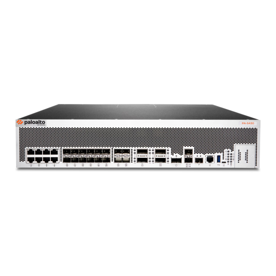
Page 14: Pa-5400 Series Front And Back Panel Descriptions
PA-5400 Series Firewall Overview PA-5400 Series Front and Back Panel Descriptions • PA-5400 Series Front Panel • PA-5400 Series Back Panel PA-5400 Series Front Panel The following image shows the front panel of the PA-5410, PA-5420, PA-5430, and PA-5440 firewalls. The table describes each front panel component. - Page 15 Four (QSFP+/QSFP28) 40Gbps/100Gbps Ethernet ports. HSCI port One 40Gbps port that can be used to connect two PA-5400 Series firewalls in a high availability (HA) configuration as follows: • In an active/passive configuration, this port is for HA2 (data link).
- Page 16 Mac or Linux computer. LED status indicators Eight LEDs that indicate the status of the firewall hardware components (see Interpret the PA-5400 Series LEDs). System Drive Cover Secures the device SSD. PA-5400 Series Next-Gen Firewall Hardware Reference 2022 Palo Alto Networks, Inc. ©...
-
Page 17: Pa-5400 Series Back Panel
For information on connecting power to the appliance, see Connect Power to a PA-5400 Series Firewall. Fan Assemblies Provide the appliance with cooling and ventilation. There are three dual-rotor fan assemblies that can be individually replaced. -
Page 18: Pa-5450 Front And Back Panel Descriptions
6. If a second NC is installed in slot 2, then up to four DPCs can be installed in the appliance instead. For more information, see PA-5400 Series Firewall Data Processor Card (DPC) PA-5400 Series Next-Gen Firewall Hardware Reference 2022 Palo Alto Networks, Inc. ©... -
Page 19: Pa-5450 Back Panel
PA-5450 Back Panel The following image shows the back panel of the PA-5450 firewall (with two AC power supplies installed) and the table describes each back panel component. PA-5400 Series Next-Gen Firewall Hardware Reference 2022 Palo Alto Networks, Inc. ©... - Page 20 For information on connecting power to the appliance, see Connect Power to a PA-5400 Series Firewall. PA-5400 Series Next-Gen Firewall Hardware Reference 2022 Palo Alto Networks, Inc.
- Page 21 PA-5400 Series Firewall Overview To view system firmware versions, use the following CLI command: admin@PA-5400> show chassis firmware PA-5400 Series Next-Gen Firewall Hardware Reference 2022 Palo Alto Networks, Inc. ©...
- Page 22 PA-5400 Series Firewall Overview PA-5400 Series Next-Gen Firewall Hardware Reference 2022 Palo Alto Networks, Inc. ©...
-
Page 23: Pa-5400 Series Firewall Module And Interface Card Information
NCs and four DPCs or one NC and five DPCs. For details on installing front slot cards, see Install the Mandatory PA-5400 Series Firewall Front Slot Cards. This chapter only covers the PA-5450. The PA-5450 is a modular firewall that makes use of interface cards for dedicated processing capabilities. -
Page 24: Pa-5400 Series Firewall Base Card (Bc)
PA-5400 Series Firewall Module and Interface Card Information PA-5400 Series Firewall Base Card (BC) The PA-5400 Series Base Card (BC) serves as the link between all static and modular components of the PA-5450 firewall. It functions as a control plane ethernet switch, a data plane traffic manager, and first packet processor subsystem. -
Page 25: Pa-5400 Series Firewall Management Processor Card (Mpc)
PA-5400 Series Firewall Module and Interface Card Information PA-5400 Series Firewall Management Processor Card (MPC) The PA-5400 Series firewall Management Processor Card (MPC) is a mandatory interface for the PA-5450 that connects to the PA-5400 Series Firewall Base Card (BC). The MPC enables management, logging, and high availability functions via SFP+ ports and features two system drives and one logging drive. - Page 26 HSCI-A and HSCI-B Quad-SFP+ (QSFP+/QSFP28) interfaces used to connect (High Speed Chassis two PA-5400 Series firewalls for a high availability (HA) Interconnect) Ports configuration. Each port offers 80GE (two 40Gbps links) or 200GE (two 100Gbps links) connectivity and is used for HA2 data link in an active/passive configuration.
- Page 27 PA-5400 Series Firewall Module and Interface Card Information Item Component Description must ensure that both the HA2 and HA2-Backup links are configured on dataplane interfaces. A mix of a dataplane port and an HSCI port for either HA2 or HA2-Backup will result in a commit failure.
- Page 28 PA-5400 Series Firewall Module and Interface Card Information Item Component Description first firewall in an HA pair to the HA1-A port on the second firewall in the pair, or connect these two ports to each other through a switch or router.
- Page 29 PA-5400 Series Firewall Module and Interface Card Information State Description FAN (Fan Green All fans are operating normally. Assemblies) A fan has encountered a failure. The card hardware failed. (Alarm) The card is operating normally. Allows a remote administrator to illuminate the SVC LED on a specific front-slot (Service) card so an on-site technician can locate the card.
- Page 30 PA-5400 Series Firewall Module and Interface Card Information State Description LED is solid blue. PA-5400 Series Next-Gen Firewall Hardware Reference 2022 Palo Alto Networks, Inc. ©...
-
Page 31: Pa-5400 Series Firewall Networking Card (Nc)
The PA-5450 firewall makes use of paired Logical Card Slots in order to direct processing power from a Data Processing Card (DPC) to a corresponding NC. The following NC can be installed in a PA-5400 Series firewall: • PA-5400 NC-A PA-5400 NC-A The PA-5400 NC-A provides up to 100Gbps Ethernet connectivity. - Page 32 PA-5400 Series Firewall Module and Interface Card Information Item Component Description LED Indicators Five LEDs that indicate the status of various hardware components. For details on the LEDs, see Interpret the PA-5400 NC-A LEDs Ethernet Ports Four 1Gbps/10Gbps BaseT RJ45 Ethernet ports.
- Page 33 PA-5400 Series Firewall Module and Interface Card Information State Description Green The card temperature is normal. (Temperature) Yellow The card temperature is outside the temperature tolerance. The card hardware failed. (Alarm) The card is operating normally. Green The card is operating normally.
- Page 34 PA-5400 Series Firewall Module and Interface Card Information State Description Enter the following command to enable the SVC LED on the card in a specific slot: admin@PA-5450> set system setting service-led enable slo t s3 yes LED is off. LED is solid blue.
-
Page 35: Pa-5400 Series Firewall Data Processor Card (Dpc)
PA-5400 Series Firewall Data Processor Card (DPC) The PA-5400 Series Data Processor Card (DPC) is a front slot card that improves the processing capacity of the PA-5450 firewall. You can install up to four or five DPCs depending on your scaling needs and slot configuration. - Page 36 PA-5400 Series Firewall Module and Interface Card Information Item Component Description LED Indicators Five LEDs that indicate the status of various hardware components. For details on the LEDs, see Interpret the PA-5400 Series DPC-A LEDs Ejector Tabs Push tabs that are used to...
- Page 37 PA-5400 Series Firewall Module and Interface Card Information State Description Service LED Slot Description Status s1 PA-5400-NC-A On s2 empty Off s3 PA-5400-DPC-A On s4 empty Off s5 empty Off s6 empty Off s7 PA-5400-MPC-A On Enter the following command to view the status for a card in a specific slot: (Continued) admin@PA-5450>...
- Page 38 PA-5400 Series Firewall Module and Interface Card Information PA-5400 Series Next-Gen Firewall Hardware Reference 2022 Palo Alto Networks, Inc. ©...
-
Page 39: Pa-5400 Series Firewall Installation
PA-5400 Series Firewall Installation The PA-5400 Series firewalls ship with racking equipment and cables that enable you to install the firewall in your deployment environment. The PA-5450 in particular is a modular system that requires you to install several components, such as network cards, during the installation process. Due to the weight... -
Page 40: Pa-5400 Series Firewall Equipment Rack Installation
Rack Installation. • Elevated ambient operating temperature—If the PA-5400 Series firewall is installed in a closed or multi-unit rack assembly, the ambient operating temperature of the rack environment may be greater than the ambient room temperature. Verify that the ambient temperature of the... - Page 41 With help from another person, hold the firewall in the rack and secure the fixed rack mount brackets to the front rack-posts using four screws for each bracket. Use the appropriate PA-5400 Series Next-Gen Firewall Hardware Reference 2022 Palo Alto Networks, Inc.
- Page 42 Slide one adjustable rack mount bracket into each of the two previously installed fixed rack mount bracket. Secure the two adjustable rack mount brackets to the back rack-posts using PA-5400 Series Next-Gen Firewall Hardware Reference 2022 Palo Alto Networks, Inc.
-
Page 43: Install The Pa-5450 Firewall In An Equipment Rack
To further reduce the weight, remove the fan trays and power supplies. The PA-5450 requires 5 RU (rack units) of rack space. Unless specified, screws are not provided. PA-5400 Series Next-Gen Firewall Hardware Reference 2022 Palo Alto Networks, Inc. ©... - Page 44 PA-5400 Series Firewall Installation STEP 1 | Read PA-5400 Series Firewall Rack Install Safety Information. STEP 2 | Slide one of the adjustable mounting brackets into the “J” shaped lip on the top edge of one of the fixed mounting brackets. Repeat with the second adjustable and fixed mounting brackets.
- Page 45 Similarly, align the slotted holes in the adjustable mounting bracket to the holes on the rear of the equipment frame. PA-5400 Series Next-Gen Firewall Hardware Reference 2022 Palo Alto Networks, Inc.
- Page 46 (not provided) compatible with your equipment frame. Tighten the screws to their recommended torque value. The mounting brackets are designed for equipment frames that are up to 32” deep (81.3 cm). PA-5400 Series Next-Gen Firewall Hardware Reference 2022 Palo Alto Networks, Inc. ©...
- Page 47 Slide the PA-5450 on the brackets that were previously mounted to the equipment frame until the front mounting flanges of the PA-5450 are flush against the mounting surface of the equipment frame. PA-5400 Series Next-Gen Firewall Hardware Reference 2022 Palo Alto Networks, Inc. ©...
- Page 48 STEP 7 | Secure the PA-5450 to the equipment frame on both sides using 8 screws each (not provided). The screws must be compatible with your equipment frame. PA-5400 Series Next-Gen Firewall Hardware Reference 2022 Palo Alto Networks, Inc. ©...
- Page 49 You may need to loosen the PA-5450 support bracket screws to align the holes in the support bracket to the threaded holes in the PA-5450 appliance. If adjustment is needed, only loosen the screws on one side at a time. PA-5400 Series Next-Gen Firewall Hardware Reference 2022 Palo Alto Networks, Inc. ©...
-
Page 50: Install The Mandatory Pa-5400 Series Firewall Front Slot Cards
Install the Mandatory PA-5400 Series Firewall Front Slot Cards The PA-5400 Series firewalls require a minimum of three cards that you install in the front slots of the appliance. These cards are shipped separately from the firewall and include the following: The Management Processor Card (MPC) provides management connectivity to the appliance and HA connectivity;... -
Page 51: Install A Pa-5400 Series Firewall Networking Card (Nc)
STEP 4 | Push on both ejector handles until they lock the card into place. Install a PA-5400 Series Firewall Networking Card (NC) STEP 1 | Attach the provided ESD strap to your wrist and plug the other end in to the ESD port location on the front of the appliance. - Page 52 Ensure that the bottom “teeth” of the blank panel fit into the notches on the bottom of the slot. Rotate the blank panel upwards until it snaps at the top of the slot. PA-5400 Series Next-Gen Firewall Hardware Reference 2022 Palo Alto Networks, Inc. ©...
-
Page 53: Configure Session Distribution On A Pa-5400 Series Firewall
Session Distribution Policies in the PAN-OS Networking Administrator’s Guide. Install a PA-5400 Series Firewall Data Processor Card (DPC) STEP 1 | Attach the provided ESD strap to your wrist and plug the other end in to the ESD port location on the front of the appliance. See... - Page 54 Ensure that the bottom “teeth” of the blank panel fit into the notches on the bottom of the slot. Rotate the blank panel upwards until it snaps at the top of the slot. PA-5400 Series Next-Gen Firewall Hardware Reference 2022 Palo Alto Networks, Inc. ©...
-
Page 55: Set Up A Connection To The Firewall
PA-5400 Series Firewall Installation Set Up a Connection to the Firewall On first startup, the PA-5400 Series firewall boots into Zero Touch Provisioning (ZTP) mode by default. ZTP mode allows you to automate the provisioning process of a new firewall that is added to a Panorama management server. - Page 56 PA-5400 Series Firewall Installation STEP 4 | Power on the firewall. See Connect Power to a PA-5400 Series Firewall to learn how to connect power to the firewall. • (Standard mode) Using your terminal emulator, watch for the following CLI prompt as the...
-
Page 57: Connect Power To A Pa-5400 Series Firewall
PA-5400 Series Firewall Installation Connect Power to a PA-5400 Series Firewall The following topics describe how to connect power to a PA-5400 Series firewall. After you power on the firewall, you can View PA-5400 Series Firewall Power Statistics. Learn how to... - Page 58 1. Connect the first two power supplies to a 120VAC 15-amp circuit breaker or 240VAC 20-amp circuit breaker using the provided power cords and then connect the second two PA-5400 Series Next-Gen Firewall Hardware Reference 2022 Palo Alto Networks, Inc.
- Page 59 DC power source. Do this for each of the four power supplies, ensuring that the first two power supplies on the left are connected to one power circuit breaker and the second pair PA-5400 Series Next-Gen Firewall Hardware Reference 2022 Palo Alto Networks, Inc.
-
Page 60: Connect Ac Or Dc Power To A Pa-5450 Firewall
Determine PA-5450 Firewall Power Configuration Requirements. Learn how to Set Up a Connection to the Firewall based on your desired boot mode prior to powering on the firewall for the first time. PA-5400 Series Next-Gen Firewall Hardware Reference 2022 Palo Alto Networks, Inc. ©... - Page 61 For DC deployments, ensure that your DC power feed is powered off. STEP 5 | Remove the four nuts from the ground studs located on the back of the appliance on the upper left side. PA-5400 Series Next-Gen Firewall Hardware Reference 2022 Palo Alto Networks, Inc. ©...
- Page 62 1. Connect the first two power supplies to a 120VAC 15-amp circuit breaker or 240VAC 20-amp circuit breaker using the provided power cords and then connect the second two PA-5400 Series Next-Gen Firewall Hardware Reference 2022 Palo Alto Networks, Inc.
- Page 63 Do this for each of the four power supplies, ensuring that the first two power supplies on the left are connected to one power circuit breaker and the second pair on the right is PA-5400 Series Next-Gen Firewall Hardware Reference 2022 Palo Alto Networks, Inc.
- Page 64 (standard mode or Zero Touch Provisioning mode) as specified in Set Up a Connection to the Firewall. PA-5400 Series Next-Gen Firewall Hardware Reference 2022 Palo Alto Networks, Inc. ©...
-
Page 65: View Pa-5400 Series Firewall Power Statistics
PA-5400 Series Firewall Installation Determine PA-5450 Firewall Power Configuration Requirements At least one active AC or DC power supply is required to operate a PA-5400 Series firewall. Factors that can change your power requirements are the number of Networking Cards (NCs) and Data Processor Cards (DPCs) used and your power redundancy requirement. - Page 66 Example Power Output from a PA-5450 Firewall Slot Component Card Status Power (w) PA-5400-BC-A Base Card PA-5400-NC-A PA-5400-NC-A empty PA-5400-DPC-A empty empty PA-5400-MPC-A FANTRAY PA-5450-FAN Present FANTRAY PA-5450-FAN Present FANTRAY PA-5450-FAN Present PA-5400 Series Next-Gen Firewall Hardware Reference 2022 Palo Alto Networks, Inc. ©...
- Page 67 As indicated in the last row of the table, the three 2200 watt power supplies provide 6600 watts and the installed hardware components (BC, MPC, DPC, NCs, and fans) use 1654 watts. If you subtract 1654 from 6600, there are 4946 watts of power remaining. PA-5400 Series Next-Gen Firewall Hardware Reference 2022 Palo Alto Networks, Inc. ©...
-
Page 68: Connect Cables To A Pa-5400 Series Firewall
Management Processor Card (MPC). You then configure the ethernet ports on the front of the device or on the Networking Card (NC) depending on which PA-5400 Series firewall you have. Finally, you connect these ports to your switch or router. - Page 69 PA-5400 Series Firewall Installation PA-5400 Series Next-Gen Firewall Hardware Reference 2022 Palo Alto Networks, Inc. ©...
-
Page 70: Verify The Pa-5450 Firewall Nc Configuration
This allows the firewall to start HA monitoring on both NCs. Use the following command to bring up a pair of NCs in an HA configuration: PA-5400 Series Next-Gen Firewall Hardware Reference 2022 Palo Alto Networks, Inc. ©... - Page 71 For example, to enable NCs installed in slot 2 of both appliances, run the following command: admin@PA-5450> request chassis power-on slot s2 target ha-pair For information on installing NCs, see Install a PA-5400 Series Firewall Networking Card (NC). PA-5400 Series Next-Gen Firewall Hardware Reference 2022 Palo Alto Networks, Inc.
- Page 72 PA-5400 Series Firewall Installation PA-5400 Series Next-Gen Firewall Hardware Reference 2022 Palo Alto Networks, Inc. ©...
-
Page 73: Service The Pa-5400 Series Firewall Hardware
Service the PA-5400 Series Firewall Hardware The following topics describes how to interpret LED information and replace field- serviceable components on a PA-5400 Series firewall. For an overview of the hardware components, see PA-5400 Series Firewall Overview. > Interpret the PA-5400 Series LEDs >... -
Page 74: Interpret The Pa-5400 Series Leds
The following table describes how to interpret the status LEDs on a PA-5410, PA-5420, PA-5430, and PA-5440 firewall. The PA-5450 LEDs are located on the interface cards. For more information, see PA-5400 Series Firewall Module and Interface Card Information. Description... - Page 75 Service the PA-5400 Series Firewall Hardware Description In an active/active configuration, the HA LED only indicates HA status for the local firewall and has two possible states (green or off); it does not indicate HA connectivity of the peer. Green indicates that the...
- Page 76 Service the PA-5400 Series Firewall Hardware Description SFP+, HA1-A and HA-1B, These ports have two LEDs each. The color of the LED differs and Management port based on the port speed. 1G—Yellow 10G—Green SFP28 and QSFP28 The SFP28 ports have two LEDs each. The QSFP28 ports have one or four corresponding LEDs each depending on if the ports are broken out or not.
- Page 77 Service the PA-5400 Series Firewall Hardware Description • FAIL (Bottom/DC LED) • Solid Green—The power supply is operating normally. • Solid Yellow—The power supply failed. This can also indicate a fan failure or overheating condition. • Blinking Yellow & Green (Alternating at 2:1 ratio)—The power supply is at high temperature.
-
Page 78: Identify Pa-5400 Series Port Activity And Link Leds
The following image shows how to identify the activity and link LEDs of the port types available on the PA-5400 Series firewalls (PA-5410, PA-5420, PA-5430, and PA-5440) or the PA-5450 NCs (Networking Cards). For details on the functions and states of the LEDS, see... -
Page 79: Replace A Pa-5400 Series Firewall Ac Or Dc Power Supply
Interpret the PA-5400 Series Firewall Power Supply LEDs Use the two following tables to learn how to interpret the LEDs on a PA-5400 Series firewall (PA-5410, PA-5420, PA-5430, and PA-5440) AC or DC power supply. The table you refer to depends on the color of the handle of your power supply. - Page 80 Service the PA-5400 Series Firewall Hardware • Solid yellow—The power supply failed. This can also indicate a fan failure or overheating condition. • Blinking yellow and green (Alternating at 2:1 ratio)—The power supply is at high temperature. OK(Top/AC LED) • Solid green—The power supply is operating normally.
-
Page 81: Replace A Pa-5400 Series Firewall Ac Or Dc Power Supply
Service the PA-5400 Series Firewall Hardware No DC power. Replace a PA-5400 Series Firewall AC or DC Power Supply The following instructions describe how to replace a power supply in a PA-5410, PA-5420, PA-5430, and PA-5440 firewall. STEP 1 | Put the provided ESD wrist strap on your wrist ensuring that the metal contact is touching your skin. -
Page 82: Replace A Pa-5450 Ac Or Dc Power Supply
A red LED indicates a failed power supply. For details on the power supply LEDs, see Interpret the PA-5400 Series Firewall Power Supply LEDs STEP 3 | Shut off power to the failed power supply. - Page 83 Service the PA-5400 Series Firewall Hardware STEP 4 | Facing the rear side of the appliance, push the power supply latch handle to the left to disengage the latch from the appliance. With the latch still pushed to the left, pull on the metal handle to slide the power supply out.
-
Page 84: Replace A Pa-5400 Series Base Card (Bc)
Service the PA-5400 Series Firewall Hardware Replace a PA-5400 Series Base Card (BC) The PA-5400 Series Base Card (BC) is not hot-swappable. In the case of a failure, you must power off the appliance and disconnect all power sources before removing the BC. - Page 85 Service the PA-5400 Series Firewall Hardware STEP 6 | Grab both BC ejector handles and swing the handles outward at the same time. Gently pull the BC outward from inside the appliance. Support the BC with one hand while pulling it out from the appliance.
-
Page 86: Replace A Pa-5400 Series Firewall Fan Assembly
Service the PA-5400 Series Firewall Hardware Replace a PA-5400 Series Firewall Fan Assembly The following topics describe how to replace a PA-5400 Series firewall fan tray. • Replace a PA-5400 Series Fan Assembly • Replace a PA-5450 Fan Assembly Replace a PA-5400 Series Fan Assembly The PA-5410, PA-5420, PA-5430, and PA-5440 have three dual-rotor, single fan assemblies on its rear side. - Page 87 Service the PA-5400 Series Firewall Hardware STEP 4 | Loosen the captive screw holding the fan assembly in place. STEP 5 | While gripping the fan assembly handle, gently pull the fan assembly out of its slot. PA-5400 Series Next-Gen Firewall Hardware Reference 2022 Palo Alto Networks, Inc.
-
Page 88: Replace A Pa-5450 Fan Assembly
Service the PA-5400 Series Firewall Hardware STEP 6 | Install the replacement fan by sliding it into the vacant fan slot. Tighten the captive screw by turning it clockwise until it is secure. Ensure that the fan assembly is secure by gently pulling on the handle. - Page 89 Service the PA-5400 Series Firewall Hardware STEP 3 | Identify the failed fan assembly by checking the fault LEDs of each fan. In the event of a failure, the LED on the fan assembly will be red. STEP 4 | Place your thumb under the thumb tab located on the bottom of the fan assembly.
- Page 90 Service the PA-5400 Series Firewall Hardware STEP 5 | While still gripping the fan assembly handle, gently pull the fan assembly out of its slot. STEP 6 | Install the replacement fan by sliding it into the vacant fan slot, ensuring that the thumb tab is on the bottom.
-
Page 91: Replace A Pa-5400 Series Firewall Front Slot Card
Service the PA-5400 Series Firewall Hardware Replace a PA-5400 Series Firewall Front Slot Card The PA-5450 is the only PA-5400 Series firewall that requires one Management Processor Card, at least one Networking Card (NC), and at least one Data Processor Card (DPC). The procedures to replace all of the front slot cards in a PA-5450 firewall are identical. - Page 92 Service the PA-5400 Series Firewall Hardware STEP 4 | Grip the front ejector handles and gently pull the card out of its slot. STEP 5 | With your replacement MPC in hand, rotate the card and align it with the front of the appliance so that the Palo Alto Networks logo is readable at the top of the card.
-
Page 93: Replace A Pa-5400 Series Networking Card (Nc)
• Replace a PA-5450 Networking Card (NC) • PA-5400 Series Firewall Networking Card (NC) Troubleshooting Commands Replace a PA-5450 Networking Card (NC) STEP 1 | Put the provided ESD wrist strap on your wrist ensuring that the metal contact is touching your skin. - Page 94 Gently push the replacement NC into slot 1 or 2 until the card reaches the end of the slot. Push on both ejector handles until they lock the card into place. PA-5400 Series Firewall Networking Card (NC) Troubleshooting Commands The following table describes common commands that you can use to troubleshoot NC issues on a PA-5400 Series firewall.
- Page 95 Service the PA-5400 Series Firewall Hardware Purpose Command Show NC slot status. Run the following to view all of the slots: admin@PA-5450> show chassis status To view the status of one slot run: admin@PA-5450> show chassis status slot <slo t-number>...
-
Page 96: Replace A Pa-5400 Series Data Processor Card (Dpc)
2 target ha-pair You can use the ha-pair option in an HA configuration for many of the slot control commands. Replace a PA-5400 Series Data Processor Card (DPC) Learn how to replace a DPC. • Replace a PA-5450 Data Processor Card (DPC) -
Page 97: Pa-5450 Front Slot And Card States
Service the PA-5400 Series Firewall Hardware STEP 3 | Grip the front ejector handles and gently pull the card out of its slot. The below image shows a Management Processor Card (MPC); however, the procedure to install the DPC is the same. -
Page 98: Pa-5450 Logical Card Slots
Service the PA-5400 Series Firewall Hardware admin@PA-5450> show chassis status slot s1 For information on troubleshooting card slots and changing slot states, see PA-5400 Series Firewall Networking Card (NC) Troubleshooting Commands. State Description Empty The slot is empty and is ready to use. - Page 99 Service the PA-5400 Series Firewall Hardware If you install a DPC in Slot 2 of the appliance, then there is no logical pairing with Slot 4. See the following table of possible CLI commands that are used to restart, power on, or power off a card.
- Page 100 Service the PA-5400 Series Firewall Hardware CLI Command Result Enable a card in the selected slot. request chassis enable slot <> request chassis enable slot <> targe t -ha-pair The status of one card in a logical pair can have an impact on the status of the other card in the pair.
- Page 101 Service the PA-5400 Series Firewall Hardware Operation Possible Outcomes Critical System Log Examples Powering • The state of the logically paired DPC off an NC is not affected when the NC fails or goes down. Powering • Using the admin-power-on or...
-
Page 102: Replace A Pa-5450 Front Slot Card In A High Availability (Ha) Configuration
Service the PA-5400 Series Firewall Hardware Replace a PA-5450 Front Slot Card in a High Availability (HA) Configuration When High Availability (HA) is configured on the firewall, you must take additional steps to remove and install a Networking Card (NC) or Data Processing Card (DPC). Although it is possible to hot-swap the front slot cards, following the procedure outlined below will prevent slot or device failures in a live HA deployment. - Page 103 Service the PA-5400 Series Firewall Hardware To install a replacement of the failed card: 1. When you receive the replacement NC or DPC, insert it into the device that needs the replacement card. 2. Issue the following command where X is the slot inserted: request chassis admin-power-on slot X target ha-pair 3.
-
Page 104: Install An Mpc Logging Drive
Service the PA-5400 Series Firewall Hardware Install an MPC Logging Drive STEP 1 | Attach an ESD strap to your wrist and plug the other end in to the ESD port location on the front of the appliance. See PA-5450 Front Panel for the location of the ESD port. - Page 105 Service the PA-5400 Series Firewall Hardware STEP 7 | Reboot the firewall after the logging drive is enabled. PA-5400 Series Next-Gen Firewall Hardware Reference 2022 Palo Alto Networks, Inc. ©...
-
Page 106: Replace A System Drive
The following topics describe how to replace the Solid State Drive (SSD) containing the files of the PA-5400 Series firewalls. The system drive is located in the front panel of the PA-5410, PA-5420, PA-5430, and PA-5440 firewalls, while the PA-5450 system drive is located in the Management Processor Card (MPC). - Page 107 Service the PA-5400 Series Firewall Hardware partition shows the status clean, degraded, and drive Sys1 is missing from the panlogs array; together, these indicate that you need to replace the Sys1 drive. admin@PA-5420> show system raid detail Overall System Drives RAID status...
- Page 108 Service the PA-5400 Series Firewall Hardware Disk id Sys2 Present (MICRON_M510DC_MT) ----------------------------------------------------------------------------- Partition status panlogs clean, degraded Drive id Sys2 active sync maint clean, degraded Drive id Sys2 active sync sysroot0 clean, degraded Drive id Sys2 active sync sysroot1 clean, degraded...
- Page 109 Service the PA-5400 Series Firewall Hardware STEP 6 | Pull the SSD module out of the firewall. STEP 7 | Remove the replacement drive from the packaging, determine the drive model, and place it on an antistatic surface. Then compare this model number with the model number of the...
- Page 110 Service the PA-5400 Series Firewall Hardware STEP 8 | Slide the replacement SSD module onto the rails and gently push it into the firewall. Re- fasten the captive screw until the module is secure in the appliance. STEP 9 | Choose from the following two installation procedures based on your findings in Step 7: •...
- Page 111 Service the PA-5400 Series Firewall Hardware STEP 10 | (Same model replacement drive only) Add the replacement drive (one that is the same model as the failed drive) to the RAID 1 array: 1. Add the replacement drive to the RAID 1 array. In this example, run the following command to add the SYS 1 drive to the array: admin@PA-5420>...
- Page 112 Service the PA-5400 Series Firewall Hardware Drive id Sys2 active sync swap clean Drive id Sys1 active sync Drive id Sys2 active sync STEP 11 | (Different model replacement drive only) Add the replacement drive (one that is a different model than the failed drive) to the RAID 1 array: 1.
- Page 113 Service the PA-5400 Series Firewall Hardware and install the second replacement drive (one that is the same model as Sys1) into the carrier. Then, install the second replacement drive in slot Sys 2. 9. Add the second replacement drive to the RAID 1 array. In this example, run the following command to add drive Sys2 to the array admin@PA-5420>...
-
Page 114: Replace A System Drive In A Pa-5450 Mpc
Service the PA-5400 Series Firewall Hardware Drive id Sys1 active sync Drive id Sys2 active sync swap clean Drive id Sys1 active sync Drive id Sys2 active sync Replace a System Drive in a PA-5450 MPC STEP 1 | Ensure that you have access to an ESD work surface for placement of the Management Processor Card (MPC). - Page 115 Before re-installing the MPC, plug the banana clip end of your ESD wrist strap into one of the ESD ports located on the back of the appliance. STEP 10 | Slide the MPC back into slot 7. See Install a PA-5400 Series Firewall Management Processor Card (MPC) for more information. PA-5400 Series Next-Gen Firewall Hardware Reference 2022 Palo Alto Networks, Inc.
- Page 116 Service the PA-5400 Series Firewall Hardware PA-5400 Series Next-Gen Firewall Hardware Reference 2022 Palo Alto Networks, Inc. ©...
-
Page 117: Pa-5400 Series Firewall Specifications
The following topics provide appliance and component specifications for the PA-5400 Series firewalls. View the datasheet for information on features, performance, and capacity numbers. > PA-5400 Series Firewall Physical Specifications > PA-5400 Series Firewall Electrical Specifications > PA-5400 Series Firewall Environmental Specifications... -
Page 118: Pa-5400 Series Firewall Physical Specifications
PA-5400 Series Firewall Specifications PA-5400 Series Firewall Physical Specifications The following table describes PA-5400 Series firewall physical specifications. Specification Value Height PA-5410, PA-5420, PA-5430, and PA-5440 firewalls—3.44 inches (8.74 cm) PA-5450 firewall—8.75 inches (22.23 cm) Depth PA-5410, PA-5420, PA-5430, and PA-5440 firewalls— 22.5 inches (57.15 cm) - Page 119 DC power supplies. The AC and DC power supplies are hot- swappable. PA-5450 firewall—Four AC or DC power supplies. The AC and DC power supplies are hot-swappable. PA-5400 Series Next-Gen Firewall Hardware Reference 2022 Palo Alto Networks, Inc. ©...
-
Page 120: Pa-5400 Series Firewall Electrical Specifications
PA-5400 Series Firewall Specifications PA-5400 Series Firewall Electrical Specifications The following table describes the PA-5400 Series firewall electrical specifications. To learn about the module and component electrical specifications of the PA-5450, see the PA-5450 Firewall Component Electrical Specifications. To learn about the power cords compatible with the... -
Page 121: Pa-5450 Firewall Component Electrical Specifications
-120 Watts Includes power allocation for optics PAN-PA-5450-FAN -230 Watts PAN-PWR-2200W- • Input Voltage—100-240VAC (50-60 Hz), Single phase • Output Power—+2200 Watts @ 200VAC or +1200 Watts @ 100VAC PA-5400 Series Next-Gen Firewall Hardware Reference 2022 Palo Alto Networks, Inc. ©... -
Page 122: Pa-5400 Series Firewall Power Cord Types
PAN-PWR-2200W- • Input Voltage— -48 to -60VDC • Output Power— +2200 Watts PA-5400 Series Firewall Power Cord Types The PA-5400 Series firewalls ship with two AC or two DC power supplies by default. SKU Number Description PAN-PWR-C19-AUS AC power cord with IEC-60320 C19 and AS/NZS 4417 cord... - Page 123 Power Cord, Taiwan, 15A, 125V, IEC-60320 C13 and CNS 10917 cord ends, 6ft PAN-PWR-CORD-UK Power Cord, United Kingdom, 10A, 250V, IEC-60320 C13 and BS 1363 UK13 cord ends, 6ft PA-5400 Series Next-Gen Firewall Hardware Reference 2022 Palo Alto Networks, Inc. ©...
-
Page 124: Pa-5400 Series Firewall Environmental Specifications
PA-5400 Series Firewall Specifications PA-5400 Series Firewall Environmental Specifications The following table describes PA-5400 Series firewall environmental specifications. Specification Value PA-5410, PA-5420, PA-5430, and PA-5440 Operating temperature range • 0° to 55°C (32° to 131°F) PA-5450 • 0° to 50° C (32° to 122°F) Storage temperature range -20°... -
Page 125: Pa-5400 Series Firewall Hardware Compliance Statements
Our products meet standards for product safety and electromagnetic compatibility when used for their intended purpose. To view compliance statements for the PA-5400 Series firewalls, see PA-5400 Series Firewall Compliance... -
Page 126: Pa-5400 Series Firewall Compliance Statements
PA-5400 Series Firewall Hardware Compliance Statements PA-5400 Series Firewall Compliance Statements The following are the PA-5400 Series firewall hardware statements: • VCCI This section provides the compliance statement for the Voluntary Control Council for Interference by Information Technology Equipment (VCCI), which governs radio frequency emissions in Japan. - Page 127 PA-5400 Series Firewall Hardware Compliance Statements • BSMI EMC Statement—User warning: This is a Class A product. When used in a residential environment it may cause radio interference. In this case, the user will be required to take adequate measures.
- Page 128 PA-5400 Series Firewall Hardware Compliance Statements PA-5400 Series Next-Gen Firewall Hardware Reference 2022 Palo Alto Networks, Inc. ©...
Need help?
Do you have a question about the PA-5400 Series and is the answer not in the manual?
Questions and answers