
Related Manuals for PaloAlto Networks PA-5000 Series


Summary of Contents for PaloAlto Networks PA-5000 Series
- Page 1 PA-5000 Series Hardware Reference Guide 11/30/10 Third/Final Review Draft - Palo Alto Networks COMPANY CONFIDENTIAL...
- Page 2 Palo Alto Networks, Inc. www.paloaltonetworks.com © 2014 Palo Alto Networks. All rights reserved. Palo Alto Networks and PAN-OS are trademarks of Palo Alto Networks, Inc. All other trademarks are the property of their respective owners. Part number: 810-000056-00E...
-
Page 3: Table Of Contents
April 7, 2014 - Palo Alto Networks COMPANY CONFIDENTIAL Table of Contents Preface ........... . About This Guide . - Page 4 Interpreting the Port LEDs ........Chapter 4 ...
-
Page 5: Preface
“Technical Support” on page 9 About This Guide This guide describes the PA-5000 Series firewall hardware, provides instructions on installing the hardware and performing maintenance procedures, and provides product specifications. This guide is intended for system administrators responsible for installing and maintaining the PA-5000 Series. -
Page 6: Typographical Conventions
Typographical Conventions Typographical Conventions This guide uses the following typographical conventions for special terms and instructions. Convention Meaning Example boldface Names of commands, Use the configure command to enter Configuration mode. keywords, and selectable items in the web interface The address of the Palo Alto Networks home page is italics Name of variables, files, configuration... -
Page 7: Related Documentation
Palo Alto Networks License and Warranty You can find other related documentation in the Technical Documentation section at http://support.paloaltonetworks.com. Obtaining More Information To obtain more information about the PA-5000 Series: • Palo Alto Networks website—Go to http://www.paloaltonetworks.com. • Online help—Click Help in the upper right corner of the GUI to access the online help system. - Page 8 Technical Support 10 • Preface Palo Alto Networks...
-
Page 9: Overview
April 7, 2014 - Palo Alto Networks COMPANY CONFIDENTIAL Chapter 1 Overview This chapter describes the features of the front and back panel of the PA-5000 Series firewall. For more information, refer to the following topics: • “Front Panel” on page 12 •... -
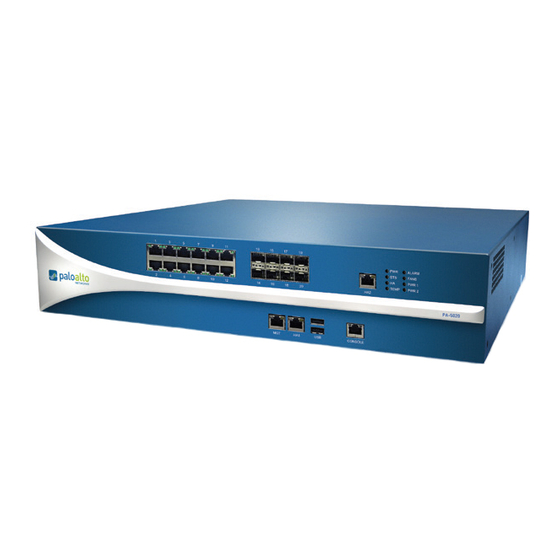
Page 10: Front Panel
Front Panel Front Panel Figure 1 shows the front panel of the PA-5060 and PA-5050 and Table 1 describes the front panel features. Ethernet SFP+ ports ports ports port 2 LEDs ALARM FANS PWR 1 TEMP PWR 2 PA-5060 CONSOLE Management Management port... - Page 11 Front Panel Figure 2 shows the front panel of the PA-5020 Series and Table 2 describes the front panel features. Ethernet ports ports port 2 LEDs ALARM FANS PWR 1 TEMP PWR 2 PA-5060 CONSOLE Management Management port port 1 ports console port Figure 2.
-
Page 12: Back Panel
Back Panel Back Panel Figure 3 shows the back panel of the PA-5000 Series and Table 3 describes the back panel features. Fan tray Hard drive bay Power supplies Figure 3. Back Panel Table 3. Back Panel Features Item Description Power supplies 2 redundant, hot-swappable power supplies. -
Page 13: Installing The Hardware
• “Connecting Power” on page 19 Before You Begin • It is recommended that two people be available to mount the PA-5000 Series in a 19-inch rack. • Have a Phillips head screwdriver available. • Verify that the intended location has adequate air circulation and meets the temperature requirements. -
Page 14: Equipment Rack Installation
Do not look directly at exposed fiber optical transmitters or cables. Figure 4 illustrates how rack mounting brackets are attached to the PA-5000 Series. You can attach the brackets using the holes at the front or the midpoint of the unit. -
Page 15: Connecting Cables To The Device
Align the mounting holes on the side of the device with holes in the rack rail. Make sure that rack rail holes are selected so that the PA-5000 Series is level. Insert mounting screws into the aligned holes. Tighten with a Phillips head screwdriver. - Page 16 Connecting Cables to the Device Figure 6 shows the cable connections of the PA-5020. Refer to Table 2 for descriptions of the front panel interfaces. Network Console Management Figure 6. Cable Connections for the PA-5020 LASER PRODUCT WARNING: PRODUCT COMPLIES WITH FDA RULE 21 CFR SUBCHAPTER J IN EFFECT AT DATE OF ...
-
Page 17: Connecting Power
Figure 7. Power Connection for the PA-5000 Series To power up the PA-5000 Series, attach a power cable to each of the power supplies and plug each into a grounded wall outlet. The device has no power switch and is automatically powered when one or more power cables are connected to the device and to an AC power source. - Page 18 Connecting Power Wind the power wires around the screws and tighten to secure. The -48VDC connection is on the left and the 0VDC connection is on the right, as labeled when facing the power supply. Turn on the electric current to the DC feed. Figure 8.
-
Page 19: Maintaining The Hardware
Replacing a Power Supply The PA-5000 Series firewall has two hot-swappable AC or DC power supplies. Both power supplies should be connected during normal operations. If the system detects a loss of power, either due to loss... -
Page 20: Replacing An Ac Power Supply
Replacing an AC Power Supply To replace the AC PWR1 or PWR2 power supply: While the PA-5000 Series is running, unplug the power cord from the power supply that you need to replace. Push the lever to the right and use the handle to slide the power supply out of the device, as shown in Figure 9. -
Page 21: Replacing A Dc Power Supply
To replace the DC PWR1 or PWR2 power supply: While the PA-5000 Series is running, loosen the screws that secure the power wires and remove the wires from the power supply that you need to replace, as shown in Figure 10. -
Page 22: Replacing A Hard Disk Or Solid State Drive
Replacing a Hard Disk or Solid State Drive Replacing a Hard Disk or Solid State Drive The PA-5000 Series firewall has a bay that contains two 2.5-inch Serial Advanced Technology Attachment (SATA) hard disk drives or solid state drives (SSD). You must power down the firewall to replace either of the drives. -
Page 23: Choosing System Options For The Drive
Replacing a Hard Disk or Solid State Drive Gently pull the lever open to partially eject the drive, and then slide the drive out from the enclosure. Figure 14. Removing a Drive Slide the replacement drive in, label side up, gently pushing it in until the lever begins to close. Gently close the lever until it clicks into place. -
Page 24: Replacing The Fan Tray And Air Filter
Replacing the Fan Tray and Air Filter • Adding blank but different drive In this scenario, the new drive is blank but has a different part number. This is the expected case when migrating from standard to SSD drives. The system will start to boot, it will determine that the drives are different, and then it will boot into maintenance mode with the reason “Drive model mismatch.”... - Page 25 Replacing the Fan Tray and Air Filter Loosen the thumbnail screws for the fan tray bay using a flat or Phillips head screw driver, if necessary. Figure 16. Loosening the Thumbnail Screws for the Fan Tray and Air Filter Remove the metal plate that covers the fan tray. Hold the fan tray handle and slide the tray out.
-
Page 26: Replacing The Air Filter
Replace the metal plate and secure the thumb screws, using a flat or Phillips head screw driver. Interpreting the Device LEDs Figure 19 shows the LED dashboard on the front panel of the PA-5000 Series, and Table 4 describes the LED functions and states. - Page 27 Interpreting the Device LEDs Table 4. Functions and States of the LED Dashboard State Description Green The device is powered. (POWER) Power is off. Green The device is operating normally. (STATUS) Yellow The device is booting up. Green This device is the current active device. Yellow This device is the current passive device.
-
Page 28: Interpreting The Port Leds
Shows green if there is a network link. Right Blinks green if there is received (RX) network activity. Table 7 describes the LEDs for the PA-5000 Series Management port. Refer to Figure 1 and Figure 2. Table 7. PA-5000 Series Management and HA1 Port LEDs Description... -
Page 29: Chapter 4 Specifications
April 7, 2014 - Palo Alto Networks COMPANY CONFIDENTIAL Chapter 4 Specifications This chapter provides specifications for the PA-5000 Series firewall. For more information, refer to the following topics: • “Physical Specifications” in the next section • “Interface Specifications” on page 32 •... -
Page 30: Interface Specifications
Interface Specifications Interface Specifications Table 9 lists the interfaces for the PA-5000 Series. Table 9. Interface Specifications Specification Description Ethernet ports 12 RJ-45 10/100/1000 ports for network traffic. SFP ports Eight Small Form-Factor Pluggable (SFP) ports for network traffic. SFP+ ports PA-5060/PA-5050 only: Four 10 Gigabit Small Form-Factor Pluggable (SFP+) ports for network traffic. -
Page 31: Environmental Specifications
Environmental Specifications Environmental Specifications Table 11 lists environmental specifications for the PA-5000 Series. Table 11. Environmental Specifications Specification Description Operating temperature range 0° to 40° C. Storage temperature range -20° to 70° C. Humidity 5% to 90% non-condensing. System air flow Side to side. - Page 32 Environmental Specifications 34 • Specifications Palo Alto Networks...
-
Page 33: Compliance Statement
This section describes the Network Equipment Building System (NEBS) requirements for the PA-5000 Series. • The PA-5000 Series is intended to be installed in a Network Telecommunication Facilities (Central Office) as part of a Common Bonding Network (CNB). • The battery return (BR) input terminals are considered to be an Isolated DC return (DC-1). -
Page 34: Vcci Statement
VCCI Statement VCCI Statement This section provides the compliance statement for the Voluntary Control Council for Interference by Information Technology Equipment (VCCI), which governs radio frequency emissions in Japan. The following information is in accordance to VCCI Class A requirements Translation: This is a Class A product. -
Page 35: Index
April 7, 2014 - Palo Alto Networks COMPANY CONFIDENTIAL Index connecting cables 17, 18 connecting power 19 air filter, replacing 28 rack mounting 16 interface specifications 32 interfaces back panel back panel 14 fan tray 14 front panel 12, 13 hard disk drive bay 14 interfaces 14 overview 14... - Page 36 VCCI 36 38 • Index Palo Alto Networks...
Need help?
Do you have a question about the PA-5000 Series and is the answer not in the manual?
Questions and answers