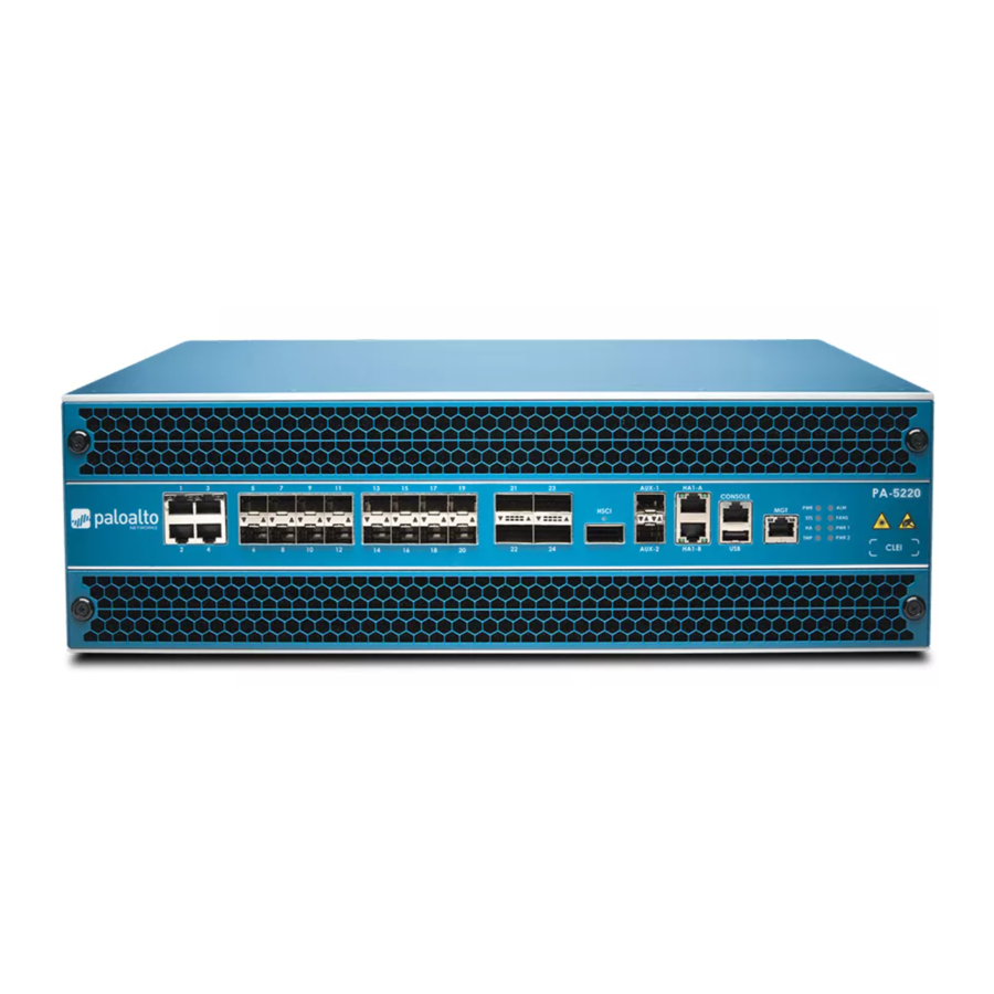
PaloAlto Networks PA-5200 Series - Next-Gen Firewall Quick Start Guide
- Hardware reference manual (60 pages) ,
- Quick start manual (2 pages) ,
- Hardware reference manual (50 pages)
Advertisement
Before You Begin
Use this document to install and begin setting up your Palo Alto Networks PA-5200 Series firewall. Refer to the PA-5200 Series Next-Gen Firewall Hardware Reference at https://www.paloaltonetworks.com/documentation/platforms for safety information, specifications, and more detailed procedures for installing the firewall.
- Verify that the installation site has an AC (or DC) power source.
- Have a #1 and #2 Phillips-head torque driver available. Use the #1 Phillips-head bit to attach the rack-mount brackets to the firewall and use the #2 bit to secure the rack-mount brackets to the equipment rack posts.
- Unpack the equipment and verify that you received the following items:
| Qty | Description |
| 1 | PA-5200 Series next-generation firewall. |
| 2 | AC power cords. If you ordered the firewall with DC power supplies, the DC power cables are not included. |
| 1 | DB-9 female to RJ-45 male console cable. |
| 2 | Velcro straps to secure the AC power cords to the power supplies. |
| 1 | Standard RJ-45 CAT6 Ethernet cable for management (MGT) port access. |
| 2 | Front rack-mount brackets used to secure the firewall to a two-post or four-post equipment rack. |
| 20 | #8-32 x 5/16" front rack-mount bracket screws to attach the front rack-mount brackets to the firewall. (Two of the twenty screws are spares.) |
| 10 | #10-32 x 3/4" rack-mount screws to secure the front rack-mount brackets to a rack with #10-32 threaded holes. (Two of the ten screws are spares.) |
| 10 | #12-24 x 1/2" rack-mount screws to secure the front rack-mount brackets to a rack with #12-24 threaded holes. (Two of the ten screws are spares.) |
| 1 | End User License Agreement (EULA). |
| 1 | China Restriction of Hazardous Substances (RoHS) declaration. |
Rack Mount the Firewall
The PA-5200 Series firewall ships with two rack-mount brackets for an installation in a two-post or four-post 19" equipment rack. If you install the firewall in a four-post rack, you can purchase an optional four-post kit to secure the firewall to the back rack posts to provide additional support. Both procedures are covered in this section.
Install the Firewall in a Two-Post Equipment Rack
- Attach one rack-mount bracket to each side of the firewall using nine #8-32 x 5/16" screws for each bracket (Figure 1) and torque to 15 in-lbs. For a two-post rack, we recommend that you install the brackets in the mid-mount position as shown in Figure 1. For a four-post rack or cabinet, install the rack-mount brackets in the front-mount position as shown in Figure 3.

![]()
![warning]() Ensure that the equipment rack is properly anchored so it can support the weight of the installed equipment without tipping.
Ensure that the equipment rack is properly anchored so it can support the weight of the installed equipment without tipping.

 Ensure that the equipment rack is properly anchored so it can support the weight of the installed equipment without tipping.
- With help from two other people, hold the firewall in place in the rack and secure the rack-mount brackets to the rack using four screws for each bracket (Figure 2). Use the appropriate screws (#10-32 x 3/4" or #12-24 x 1/2") for your rack and torque to 25 in-lbs. Use cage nuts (not provided) to secure the screws if the rack has square holes.


(Optional) Install the Four-Post Rack Kit
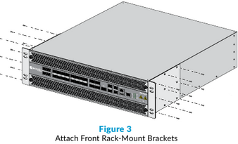
- Attach one rack-mount bracket to each side of the firewall using nine #8-32 x 5/16" screws for each bracket (Figure 3) and torque to 15 in-lbs. Ensure that the rack-mount brackets are positioned at the front of the firewall.
- Attach one side rack-mount rail to each side of the firewall using four #8-32 x 5/16" screws for each bracket (Figure 4) and torque to 15 in-lbs. Ensure that the beveled edge on each bracket is facing the firewall.

- With help from two other people, hold the firewall in the rack and secure the rack-mount brackets to the rack using four screws for each bracket (Figure 5). Use the appropriate screws (#10-32 x 3/4" or #12-24 x 1/2") for your rack and torque to 25 in-lbs. Use cage nuts (not provided) to secure the screws if the rack has square holes.

- Slide one back rack-mount bracket into each of the two previously installed side rack-mount rails (Figure 5) and secure the back brackets to the back rack posts (Figure 6) using four screws for each bracket (#10-32 x 3/4" or #12-24 x 1/2" screws) and torque to 25 in-lbs.


Power On the Firewall
The PA-5200 Series firewall ships with either two AC or two DC power supplies to provide power redundancy. This section describes how to connect AC power. For information on connecting DC power, refer to the PA-5200 Series Next-Gen Firewall Hardware Reference at https://www.paloaltonetworks.com/documentation/platforms.
- Remove the nuts, star washers, and two-post ground lug from the two-post ground studs and attach a 6-AWG ground cable (not included) to the two-post ground lug. Reinstall the ground lug and secure it to the studs using the star washers and nuts and torque to 25 in-lbs (Figure 7). Connect the other end of the ground cable to earth ground.

- Connect one of the AC power cords to power input 1 on the back of the firewall (Figure 8) and secure the cord to the power supply using the Velcro strap (Figure 9).

- Connect the other end of the power cord to an AC power source. After power is connected, the green OK LED on the power supply shows green and the corresponding LED (PWR 1 or PWR 2) on the front of the firewall shows green.
- Connect a second power cord to power input 2, secure it to the power supply with the Velcro strap, and connect the other end of the cord to an AC power source.
![]() Connect the second power cord through a different circuit breaker to provide power redundancy and allow for electrical circuit maintenance.
Connect the second power cord through a different circuit breaker to provide power redundancy and allow for electrical circuit maintenance.


Connect to the Management Interface
- Connect the standard RJ-45 Ethernet cable from the RJ-45 port on your computer to the MGT port on the firewall (Figure 10).
 Port")
- Change the IP address on your computer to an address in the 192.168.1.0/24 network, such as 192.168.1.2.
- From a web browser, go to https://192.168.1.1.
- When prompted, log in to the web interface using the default username and password (admin/admin).
(Optional) If you are not able to connect to the management web interface, you can check the status of the firewall by connecting to the console port using the DB-9 to RJ-45 serial cable (provided) and terminal emulation software. The console connection provides access to firewall boot messages, maintenance mode, and the command line interface (CLI).
 Port")
Where to Go Next
- To learn more about the firewall, refer to the PA-5200 Series Next-Gen Firewall Hardware Reference: https://www.paloaltonetworks.com/documentation/platforms.
- To learn how to configure Palo Alto Networks firewalls, go to the Technical Documentation portal: https://www.paloaltonetworks.com/documentation.
(Use the Getting Started information in the PAN-OS Administrator's Guide for initial configuration tasks.) - To contact support, go to: https://www.paloaltonetworks.com/company/contact-support.
Documents / Resources
References
Download manual
Here you can download full pdf version of manual, it may contain additional safety instructions, warranty information, FCC rules, etc.
Download PaloAlto Networks PA-5200 Series - Next-Gen Firewall Quick Start Guide
Advertisement


Need help?
Do you have a question about the PA-5200 Series and is the answer not in the manual?
Questions and answers