Table of Contents
Advertisement
Advertisement
Table of Contents

Related Manuals for PaloAlto Networks PA-500


Summary of Contents for PaloAlto Networks PA-500
- Page 1 PA-500 Hardware Reference Guide...
-
Page 2: About This Guide
About this Guide This guide describes the PA-500 firewall hardware, provides instructions on installing the hardware, describes how to perform maintenance procedures, and provides product specifications. This guide is intended for system administrators responsible for installing and maintaining the PA-500 firewall. -
Page 3: Table Of Contents
February 29, 2016 - Palo Alto Networks COMPANY CONFIDENTIAL Table of Contents Chapter 1 Overview ..........Front Panel . - Page 4 BSMI EMC Statement ......... . 4 •...
-
Page 5: Chapter 1 Overview
February 29, 2016 - Palo Alto Networks COMPANY CONFIDENTIAL Chapter 1 Overview This chapter describes the front and back panels of the PA-500 firewall. For more information, refer to the following topics: • “Front Panel” in the next section •... -
Page 6: Front Panel
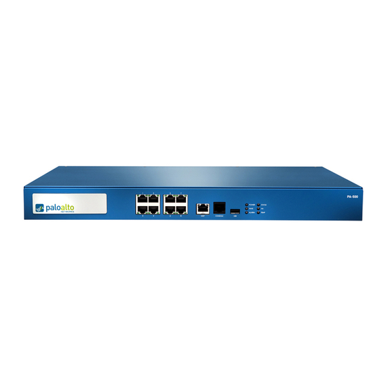
Front Panel Front Panel Figure 1 shows the front panel of the PA-500 firewall. Ethernet LEDs ports Management Console port port port Figure 1. Front Panel Table 1 describes the front panel features. Table 1. Front Panel Features Item Description Ethernet ports 8 RJ-45 10/100/1000 ports for network traffic. -
Page 7: Back Panel
Back Panel Back Panel Figure 2 shows the back panel of the PA-500 and Table 2 describes the back panel features. AC power Inlet Fans Figure 2. Back Panel Table 2. Back Panel Features Item Description Fans Two fans for cooling the device. - Page 8 Back Panel 8 • Overview Palo Alto Networks...
-
Page 9: Installing The Hardware
February 29, 2016 - Palo Alto Networks COMPANY CONFIDENTIAL Chapter 2 Installing the Hardware This chapter describes how to install the PA-500. For more information, refer to the following topics: • “Tamper Proof Statement” on page 9 • “Before You Begin” in the next section •... -
Page 10: Equipment Rack Installation
Allow clear space on the sides and back of the firewall. Equipment Rack Installation Figure 3 shows how rack mounting brackets are attached to the PA-500. You can attach the brackets using the holes at the front of the unit. -
Page 11: Connecting Cables To The Device
Make sure that rack rail holes are selected so that the PA-500 is level. Insert mounting screws into the aligned holes. Tighten with a Phillips screwdriver. Connecting Cables to the Device Figure 4 shows the PA-500 cable connections. Refer to Table 1 for descriptions of the front panel interfaces. Network... - Page 12 Connecting Power 12 • Installing the Hardware Palo Alto Networks...
-
Page 13: Maintaining The Hardware
February 29, 2016 - Palo Alto Networks COMPANY CONFIDENTIAL Chapter 3 Maintaining the Hardware This chapter provides maintenance information for the PA-500 hardware. For more information, refer to the following topics: • “Cautions and Warnings” in the next section •... -
Page 14: Interpreting The Device Leds
Interpreting the Device LEDs • Removal of equipment top cover is to be performed only by trained service person(s). The only exception is to perform a memory upgrade as described in the PA-500 memory upgrade procedures located on the platforms page. -
Page 15: Interpreting The Port Leds
Interpreting the Port LEDs Interpreting the Port LEDs Each Ethernet port on the PA-500 has two LEDs. Table 4 describes the LEDs. Table 4. Port LEDs Description Left Shows green if there is a network link. Right Blinks if there is network activity. - Page 16 Interpreting the Port LEDs 16 • Maintaining the Hardware Palo Alto Networks...
-
Page 17: Chapter 4 Specifications
February 29, 2016 - Palo Alto Networks COMPANY CONFIDENTIAL Chapter 4 Specifications This chapter provides specifications for the PA-500. For more information, refer to the following topics: • “Physical Specifications” in the next section • “Interface Specifications” on page 18 •... -
Page 18: Interface Specifications
• Parity: none • Stop bits: 1 • Flow control: none USB port One USB port for future use. Electrical Specifications Table 7 lists the electrical specifications for the PA-500. Table 7. Electrical Specifications Specification Description Input frequency 50-60 Hz... -
Page 19: Compliance Statements
February 29, 2016 - Palo Alto Networks COMPANY CONFIDENTIAL Chapter 5 Compliance Statements This section lists the hardware compliance statements for the following: • “VCCI” in the next section • “BSMI EMC Statement” on page 19 VCCI This section provides the compliance statement for the Voluntary Control Council for Interference by Information Technology Equipment (VCCI), which governs radio frequency emissions in Japan. - Page 20 BSMI EMC Statement BSMI EMC 聲明 警告使用者 : 這是甲類的資訊產品 , 在居住的環境中使用時 , 可能會造成射頻干擾 , 在這種情況下 , 使用者會被要求採取某些適當的對策 製造商:偉創力國際 原產地:美國 / 部份零組件產地為美國及其它國家。 輸入頻率:50-60 赫茲(Hz) 輸入電壓(AC) :100 〜 240 伏特 20 • Compliance Statements Palo Alto Networks...
Need help?
Do you have a question about the PA-500 and is the answer not in the manual?
Questions and answers