PaloAlto Networks PA-5200 Series Hardware Reference Manual
Next-gen firewall
Hide thumbs
Also See for PA-5200 Series:
- Quick start manual ,
- Hardware reference manual (25 pages) ,
- Quick start manual (2 pages)

Related Manuals for PaloAlto Networks PA-5200 Series


Summary of Contents for PaloAlto Networks PA-5200 Series
- Page 1 PA-5200 Series Next-Gen Firewall Hardware Reference paloaltonetworks.com/documentation...
- Page 2 2019-2019 Palo Alto Networks, Inc. Palo Alto Networks is a registered trademark of Palo © Alto Networks. A list of our trademarks can be found at www.paloaltonetworks.com/company/ trademarks.html. All other marks mentioned herein may be trademarks of their respective companies. Last Revised April 8, 2019 PA-5200 SERIES NEXT-GEN FIREWALL HARDWARE REFERENCE |...
-
Page 3: Table Of Contents
Service the PA-5200 Series Firewall............31 Interpret the LEDs on a PA-5200 Series Firewall................33 Replace the Air Intake Filters on a PA-5200 Series Firewall............35 Replace a Fan Tray on a PA-5200 Series Firewall................37 Replace a Power Supply on a PA-5200 Series Firewall..............38 Replace an AC Power Supply on a PA-5200 Series Firewall..........38... - Page 4 TABLE OF CONTENTS...
-
Page 5: Before You Begin
Before You Begin Read the following topics before you install or service a Palo Alto Networks next-generation ® firewall or appliance. The following topics apply to all Palo Alto Networks firewalls and appliances except where noted. > Tamper Proof Statement >... - Page 6 PA-5200 SERIES NEXT-GEN FIREWALL HARDWARE REFERENCE | Before You Begin 2019 Palo Alto Networks, Inc. ©...
-
Page 7: Tamper Proof Statement
• The integrity of the warranty label on the firewall or appliance is not compromised. (PA-7000 Series firewalls only) PA-7000 Series firewalls are modular systems and therefore do not include a warranty label on the firewall. PA-5200 SERIES NEXT-GEN FIREWALL HARDWARE REFERENCE | Before You Begin 2019 Palo Alto Networks, Inc. ©... -
Page 8: Third-Party Component Support
Third-Party Component Support Before you consider installing third-party hardware, read the Palo Alto Networks Third-Party Component Support statement. PA-5200 SERIES NEXT-GEN FIREWALL HARDWARE REFERENCE | Before You Begin 2019 Palo Alto Networks, Inc. ©... -
Page 9: Product Safety Warnings
• Le dispositif de protection doit être raccordé à la terre et un câble Ethernet blindé de catégorie 5E ou supérieure doit être utilisé. Caractéristiques techniques: PA-5200 SERIES NEXT-GEN FIREWALL HARDWARE REFERENCE | Before You Begin 2019 Palo Alto Networks, Inc. ©... - Page 10 • The DC battery return wiring on the firewall must be connected as an isolated DC (DC-I) return. French Translation: Le câblage de retour de batterie c.c. sur le pare-feu doit être raccordé en tant que retour c.c. isolé (CC-I). PA-5200 SERIES NEXT-GEN FIREWALL HARDWARE REFERENCE | Before You Begin 2019 Palo Alto Networks, Inc. ©...
- Page 11 • A suitably-rated DC mains disconnect device must be provided as part of the building installation. French Translation: Un interrupteur d'isolement suffisant doit être fourni pendant l'installation du bâtiment. PA-5200 SERIES NEXT-GEN FIREWALL HARDWARE REFERENCE | Before You Begin 2019 Palo Alto Networks, Inc. ©...
- Page 12 PA-5200 SERIES NEXT-GEN FIREWALL HARDWARE REFERENCE | Before You Begin...
-
Page 13: Pa-5200 Series Firewall Overview
PA-5280 firewall has double the dataplane memory, which doubles the session capacity. The following topics describe the hardware features of the PA-5200 Series firewalls. To view or compare performance and capacity information, refer to the Product Selection tool. > PA-5200 Front Panel... - Page 14 PA-5200 SERIES NEXT-GEN FIREWALL HARDWARE REFERENCE | PA-5200 Series Firewall Overview 2019 Palo Alto Networks, Inc. ©...
-
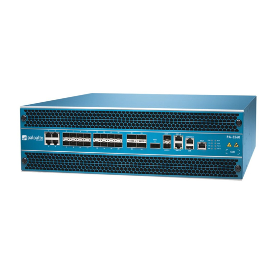
Page 15: Pa-5200 Front Panel
PA-5200 Front Panel The following image shows the front panel of the PA-5200 Series firewall and the table describes each front panel component. The only differences between the PA-5220 (shown), PA-5250, PA-5260, and PA-5280 panels is the model name and the Ethernet port speeds as described in the table. - Page 16 (MRT), and the command line interface (CLI). If your management computer does not have a serial port, use a USB-to- serial converter. Serial Settings Data rate: 9600 PA-5200 SERIES NEXT-GEN FIREWALL HARDWARE REFERENCE | PA-5200 Series Firewall Overview 2019 Palo Alto Networks, Inc. ©...
- Page 17 Intake air filters Two filters for air entering the firewall. Replace the Air Intake Filters on a PA-5200 Series Firewall every six months. PA-5200 SERIES NEXT-GEN FIREWALL HARDWARE REFERENCE | PA-5200 Series Firewall Overview 2019 Palo Alto Networks, Inc. ©...
-
Page 18: Pa-5200 Back Panel
PA-5200 Back Panel The following image shows the back panel of PA-5200 Series firewalls and the table describes each back- panel component. The only difference between PA-5200 Series firewall back panels is the power supply type installed—they each can have two AC or two DC power supplies. The image shows a PA-5220 firewall with AC power supplies. -
Page 19: Install The Pa-5200 Series Firewall In An Equipment Rack
Install the PA-5200 Series Firewall in an Equipment Rack The PA-5200 Series next-generation firewall ships with two rack-mount brackets for installation in a two-post or four-post 19” equipment rack. If you install the firewall in a four- post rack, you can purchase and install the optional four-post rack kit to secure the firewall to the back rack posts for additional support. - Page 20 PA-5200 SERIES NEXT-GEN FIREWALL HARDWARE REFERENCE | Install the PA-5200 Series Firewall in an Equipment Rack 2019 Palo Alto Networks, Inc. ©...
-
Page 21: Install The Pa-5200 Series Firewall In A 19-Inch Equipment Rack
Install the PA-5200 Series Firewall in a 19-inch Equipment Rack The following procedure describes how to install the PA-5200 Series firewall in a two-post or four-post equipment rack. When installing the firewall in a two-post equipment rack, ensure that the rack is properly anchored and can support the weight of the installed equipment. -
Page 22: Install The Four-Post Rack Kit On A Pa-5200 Series Firewall
(#10-32 x 3/4” or #12-24 x 1/2”) for your rack and torque to 25 in-lbs. Use cage nuts (not provided) to secure the screws if the rack has square holes. PA-5200 SERIES NEXT-GEN FIREWALL HARDWARE REFERENCE | Install the PA-5200 Series Firewall in an Equipment Rack 2019 Palo Alto Networks, Inc. - Page 23 3/4” or #12-24 x 1/2”) and torque to 25 in-lbs. Use cage nuts (not provided) to secure the screws if the rack has square holes. PA-5200 SERIES NEXT-GEN FIREWALL HARDWARE REFERENCE | Install the PA-5200 Series Firewall in an Equipment Rack 2019 Palo Alto Networks, Inc.
- Page 24 PA-5200 SERIES NEXT-GEN FIREWALL HARDWARE REFERENCE | Install the PA-5200 Series Firewall in an Equipment Rack...
-
Page 25: Connect Power To A Pa-5200 Series Firewall
Connect Power to a PA-5200 Series Firewall PA-5200 Series firewalls have either two AC or two DC power supplies (the second power supply is for redundancy). The firewall requires a 100-240VAC (50-60 Hz) or -40 to -60VDC power source, depending on the type of power supplies installed in the firewall (AC or DC).For more details on power requirements and power consumption, see PA-5200 Series Electrical Specifications. - Page 26 PA-5200 SERIES NEXT-GEN FIREWALL HARDWARE REFERENCE | Connect Power to a PA-5200 Series Firewall 2019 Palo Alto Networks, Inc. ©...
-
Page 27: Connect Ac Power To A Pa-5200 Series Firewall
Connect AC Power to a PA-5200 Series Firewall The following procedure describes how to connect AC power to a PA-5200 Series firewall with AC power supplies. ® To avoid injury to yourself or damage to your Palo Alto Networks hardware or the data that Product Safety Warnings. -
Page 28: Connect Dc Power To A Pa-5200 Series Firewall
Connect DC Power to a PA-5200 Series Firewall The following procedure describes how to connect DC power to a PA-5200 Series firewall with DC power supplies. ® To avoid injury to yourself or damage to your Palo Alto Networks hardware or the data that Product Safety Warnings. - Page 29 STEP 5 | After all DC power cables are securely connected, power on the DC power source. PA-5200 SERIES NEXT-GEN FIREWALL HARDWARE REFERENCE | Connect Power to a PA-5200 Series Firewall 2019 Palo Alto Networks, Inc. ©...
- Page 30 PA-5200 SERIES NEXT-GEN FIREWALL HARDWARE REFERENCE | Connect Power to a PA-5200 Series Firewall...
-
Page 31: Service The Pa-5200 Series Firewall
Service the PA-5200 Series Firewall The following topics describe how to interpret the PA-5200 Series firewall status LEDs and describes how to replace the serviceable components. > Interpret the LEDs on a PA-5200 Series Firewall > Replace the Air Intake Filters on a PA-5200 Series Firewall >... - Page 32 PA-5200 SERIES NEXT-GEN FIREWALL HARDWARE REFERENCE | Service the PA-5200 Series Firewall 2019 Palo Alto Networks, Inc. ©...
-
Page 33: Interpret The Leds On A Pa-5200 Series Firewall
Interpret the LEDs on a PA-5200 Series Firewall The following table describes how to interpret the status LEDs on a PA-5200 Series firewall. Description Front Panel LEDs PWR (Power) Green—The firewall is powered on. Off—The firewall is not powered on or an error occurred with the internal power system (for example, power is not within tolerance levels). - Page 34 Green—The fan trays and all fans are operating normally. Red—One or more fans in the fan tray failed (see Replace a Fan Tray on a PA-5200 Series Firewall). PA-5200 SERIES NEXT-GEN FIREWALL HARDWARE REFERENCE | Service the PA-5200 Series Firewall 2019 Palo Alto Networks, Inc. ©...
-
Page 35: Replace The Air Intake Filters On A Pa-5200 Series Firewall
Install a new filter into the filter cover ensuring that you slide it under the filter cover cross bars. You can install the filter with either side facing up. PA-5200 SERIES NEXT-GEN FIREWALL HARDWARE REFERENCE | Service the PA-5200 Series Firewall 2019 Palo Alto Networks, Inc. - Page 36 Replace the top filter cover and filter and turn the two thumb screws clockwise to secure the cover to the firewall. STEP 5 | Repeat this procedure to replace the bottom air filter. PA-5200 SERIES NEXT-GEN FIREWALL HARDWARE REFERENCE | Service the PA-5200 Series Firewall 2019 Palo Alto Networks, Inc. ©...
-
Page 37: Replace A Fan Tray On A Pa-5200 Series Firewall
Firewall PA-5200 Series firewalls have two fan trays and each fan tray contains four fans. If one fan on a fan tray fails, the LED on the fan tray turns red. When this occurs, immediately replace the fan tray to avoid service interruption. -
Page 38: Replace A Power Supply On A Pa-5200 Series Firewall
Replace a Power Supply on a PA-5200 Series Firewall PA-5200 Series firewalls have either two AC or two DC power supplies (the second power supply is for redundancy). If one power supply fails, you can replace it without service interruption as described in the following procedures. -
Page 39: Replace A Dc Power Supply On A Pa-5200 Series Firewall
Remove the replacement power supply from the packaging and slide it into the empty power supply slot. Push the power supply all the way in until the release lever clicks and secures the power supply. PA-5200 SERIES NEXT-GEN FIREWALL HARDWARE REFERENCE | Service the PA-5200 Series Firewall 2019 Palo Alto Networks, Inc. ©... - Page 40 STEP 7 | When all DC power cables are securely connected and the plastic guard is properly reattached, power on the DC power source. PA-5200 SERIES NEXT-GEN FIREWALL HARDWARE REFERENCE | Service the PA-5200 Series Firewall 2019 Palo Alto Networks, Inc. ©...
-
Page 41: Replace A Drive On A Pa-5200 Series Firewall
Replace a Drive on a PA-5200 Series Firewall The PA-5200 Series firewalls have two solid-state drives (SSDs) used for system files and system logs and two hard-disk drives (HDDs) used for network traffic log storage. Each drive pair is in a RAID 1 array so that if a drive fails, you can replace the failed drive (using the same model drive) without service interruption. - Page 42 1. Ensure that the drive carrier lever is in the open position; if it is not, press the ejector button on the drive carrier to release the lever and pull it out until it is fully open. PA-5200 SERIES NEXT-GEN FIREWALL HARDWARE REFERENCE | Service the PA-5200 Series Firewall 2019 Palo Alto Networks, Inc.
- Page 43 Available. (Optional) Suspend the firewall with the failed drive if it is the active firewall in an HA configuration. PA-5200 SERIES NEXT-GEN FIREWALL HARDWARE REFERENCE | Service the PA-5200 Series Firewall 2019 Palo Alto Networks, Inc. ©...
- Page 44 The following output shows that both drives are in the active sync state: Disk Pair Log Available Status clean Disk id Log1 Present model : ST2000NX0999 PA-5200 SERIES NEXT-GEN FIREWALL HARDWARE REFERENCE | Service the PA-5200 Series Firewall 2019 Palo Alto Networks, Inc. ©...
-
Page 45: Replace A System Drive On A Pa-5200 Series Firewall
Drive id Sys1 active sync Drive id Sys2 active sync sysroot1 clean Drive id Sys1 active sync Drive id Sys2 active sync pancfg clean PA-5200 SERIES NEXT-GEN FIREWALL HARDWARE REFERENCE | Service the PA-5200 Series Firewall 2019 Palo Alto Networks, Inc. ©... - Page 46 Press the ejector button on the drive carrier to release the carrier handle and gently pull the STEP 4 | handle toward you to remove the carrier and drive. PA-5200 SERIES NEXT-GEN FIREWALL HARDWARE REFERENCE | Service the PA-5200 Series Firewall 2019 Palo Alto Networks, Inc. ©...
- Page 47 Because the firewall recognizes that a drive is missing and it will automatically reformat the newly inserted drive and adds it to the array. PA-5200 SERIES NEXT-GEN FIREWALL HARDWARE REFERENCE | Service the PA-5200 Series Firewall 2019 Palo Alto Networks, Inc. ©...
- Page 48 3. Reboot the firewall with the failed drive into the MRT by running the following command: admin@PA-5020> debug system maintenance-mode 4. Press Enter on CONTINUE and then navigate to RAID and press Enter again. PA-5200 SERIES NEXT-GEN FIREWALL HARDWARE REFERENCE | Service the PA-5200 Series Firewall 2019 Palo Alto Networks, Inc. ©...
- Page 49 Drive id Sys1 active sync Drive id Sys2 active sync pancfg clean Drive id Sys1 active sync Drive id Sys2 active sync panrepo clean PA-5200 SERIES NEXT-GEN FIREWALL HARDWARE REFERENCE | Service the PA-5200 Series Firewall 2019 Palo Alto Networks, Inc. ©...
- Page 50 Drive id Sys1 active sync Drive id Sys2 active sync swap clean Drive id Sys1 active sync Drive id Sys2 active sync PA-5200 SERIES NEXT-GEN FIREWALL HARDWARE REFERENCE | Service the PA-5200 Series Firewall...
-
Page 51: Pa-5200 Series Firewall Specifications
PA-5200 Series Firewall Specifications The following topics describe the PA-5200 Series firewall hardware specifications. For feature, capacity, and performance information, refer to the PA-5200 Series firewall datasheet. > PA-5200 Series Physical Specifications > PA-5200 Series Electrical Specifications > PA-5200 Series Environmental Specifications... - Page 52 PA-5200 SERIES NEXT-GEN FIREWALL HARDWARE REFERENCE | PA-5200 Series Firewall Specifications 2019 Palo Alto Networks, Inc. ©...
-
Page 53: Pa-5200 Series Physical Specifications
PA-5200 Series Physical Specifications The following table describes PA-5200 Series firewall physical specifications. The physical specifications are identical for all PA-5200 Series models (PA-5220, PA-5250, PA-5260, and PA-5280 firewalls). Specification Value Rack units and dimensions Rack units—3U Dimensions—5.25”H X 21”D X 17.25”W (13.33cm X 52.07cm X 43.81cm) -
Page 54: Pa-5200 Series Electrical Specifications
• DC power supplies—19A@-40VDC, 12.7A@-60VDC Maximum inrush current The following values include both power supplies. • AC power supplies—50A@230VAC, 50A@120VAC • DC power supplies—200A@72VDC PA-5200 SERIES NEXT-GEN FIREWALL HARDWARE REFERENCE | PA-5200 Series Firewall Specifications 2019 Palo Alto Networks, Inc. ©... -
Page 55: Pa-5200 Series Environmental Specifications
• AC Power Supplies • Average—73 dB(A) • Maximum—86 dB(A) • DC Power Supplies • Average—67 dB(A) • Maximum—86 dB(A) Maximum operating altitude 10,000ft (3,048m) PA-5200 SERIES NEXT-GEN FIREWALL HARDWARE REFERENCE | PA-5200 Series Firewall Specifications 2019 Palo Alto Networks, Inc. ©... -
Page 56: Pa-5200 Series Miscellaneous Specifications
PA-5200 Series Miscellaneous Specifications The following table describes the PA-5200 Series firewall miscellaneous specifications. Specification Value Mean time between failures (MTBF) 9 years Sotrage Capacity • System file storage—240GB (Two 240GB solid-state drives (SSDs) in a RAID-1 pair). • Log storage—2TBs (Two 2TB hard disk drives (HDDs) in a RAID-1 pair). -
Page 57: Pa-5200 Series Firewall Compliance Statements Overview
Our products meet standards for product safety and electromagnetic compatibility when used for their intended purpose.To view compliance statements for the PA-3200 Series firewalls, see PA-5200 Series Firewall Compliance Statements. - Page 58 PA-5200 SERIES NEXT-GEN FIREWALL HARDWARE REFERENCE | PA-5200 Series Firewall Compliance Statements Overview 2019 Palo Alto Networks, Inc. ©...
-
Page 59: Pa-5200 Series Firewall Compliance Statements
• NEBS Requirements The following lists the Network Equipment Building System (NEBS) requirements for PA-5200 Series firewalls. • The firewall is intended to be installed in a Network Telecommunication Facility (Central Office) as part of a Common Bonding Network (CBN) or Isolated Bonding Network (IBN). - Page 60 PA-5200 SERIES NEXT-GEN FIREWALL HARDWARE REFERENCE | PA-5200 Series Firewall Compliance Statements Overview...
Need help?
Do you have a question about the PA-5200 Series and is the answer not in the manual?
Questions and answers