Table of Contents
Advertisement
Quick Links
Advertisement
Table of Contents

Related Manuals for ICP DAS USA I-8014W


Summary of Contents for ICP DAS USA I-8014W
- Page 1 I-8014W User Manual 250 KS/s, 16-bit, 8-channel differential/16-channel single-ended analog input module Version 1.0.1/ September 2011 I-8014W API User Manual, v 1.0.1, September 2011 E-mail: service@icpdas.com Copyright © 2011 ICP DAS Co., Ltd. All Rights Reserved.
- Page 2 If you have any problem, please feel free to contact us. You can count on us for quick response. Email: service@icpdas.com I-8014W API User Manual, v 1.0.1, September 2011 E-mail: service@icpdas.com Copyright © 2011 ICP DAS Co., Ltd. All Rights Reserved.
-
Page 3: Table Of Contents
Internal hardware trigger method External hardware trigger method FIFO ......................42 Magic Scan Procedure ................43 Magic Scan Example ................44 I-8014W API User Manual, v 1.0.1, September 2011 E-mail: service@icpdas.com Copyright © 2011 ICP DAS Co., Ltd. All Rights Reserved. - Page 4 Troubleshooting ............... 88 How to verify the AI function on WinCE or WES unit? Service-request requirement Why does the data read from I-8014W seem unstable? How to solve FIFO LATCHED error (-6)? I-8014W API User Manual, v 1.0.1, September 2011 E-mail: service@icpdas.com...
-
Page 5: Preface
Preface The I-8014W is a 16-bit resolution, high speed isolated analog input module providing 16 single-ended or 8 differential analog input channels. Besides basic usage knowledge and SDK interface, this manual intends to introduce the Magic Scan function of I-8014W for scanning multi-channel system. -
Page 6: Hardware
5 to 95 % RH, Non-condensing Dimensions (W x L x H) 30 mm x 102 mm x 115 mm I-8014W API User Manual, v 1.0.1, September 2011 E-mail: service@icpdas.com Copyright © 2011 ICP DAS Co., Ltd. All Rights Reserved. -
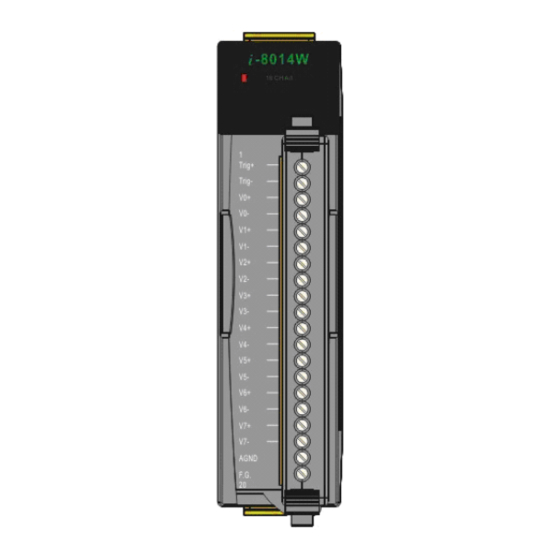
Page 7: Pin Assignments
Pin Assignments I-8014W API User Manual, v1.0.1, June 2011 Copyright © 2011 ICP DAS Co., Ltd. All Rights Reserved. E-mail: service@icpdas.com... -
Page 8: Jumper Setting
Jumper setting Secondary FPGA Primary FPGA Differential / Single Ended select jumper Input impedance select jumper I-8014W API User Manual, v 1.0.1, September 2011 E-mail: service@icpdas.com Copyright © 2011 ICP DAS Co., Ltd. All Rights Reserved. - Page 9 Input impedance adjustment The I-8014W provides three input impedances such as 20k, 200k (default setting) and 20M Ohm to meet system requirement. For most of cases, 200k is good enough. Every time when the input impedance is changed on a calibrated module, it is...
-
Page 10: Wire Connection
While measuring current input, it is no use to enhance to accuracy. I-8014W API User Manual, v1.0.1, June 2011 Copyright © 2011 ICP DAS Co., Ltd. All Rights Reserved. E-mail: service@icpdas.com... -
Page 11: Block Diagram
Block Diagram I-8014W API User Manual, v 1.0.1, September 2011 E-mail: service@icpdas.com Copyright © 2011 ICP DAS Co., Ltd. All Rights Reserved. -
Page 12: Demo Programs Location
Demo Programs Location The following table lists the location of I-8014W demo programs for different platform for verifying the functions of the I-8014W and reusing the source code if needed. Platform Location For I-8000 on Web Library ftp://ftp.icpdas.com/pub/cd/8000cd/napdos/8000/841x881x/demo/li Demo ftp://ftp.icpdas.com/pub/cd/8000cd/napdos/8000/841x881x/demo/i... - Page 13 XP-8000 ftp://ftp.icpdas.com/pub/cd/xp-8000/demo/specialized_io/ ftp://ftp.icpdas.com/pub/cd/xpac-atom/sdk/io/ XP-8000 -Atom ftp://ftp.icpdas.com/pub/cd/xpac-atom/demo/specialized_io/ For Windows Embedded Standard on CD CD:\SDK\IO XP-8000 CD:\Demo\Specialized_IO CD:\SDK\IO XP-8000 -Atom CD:\Demo\Specialized_IO I-8014W API User Manual, v 1.0.1, September 2011 E-mail: service@icpdas.com Copyright © 2011 ICP DAS Co., Ltd. All Rights Reserved.
-
Page 14: Quick Start
Calibration, page 17 Getting Started Guide The executable file AI_INFO.EXE in basic_info folder of I-8014W demo could be used to get the basic information of the I-8014W and verify the AI read function. The basic information includes: ● Version number and published date of library. - Page 15 8, make sure the Differential / Single Ended select jumper is in differential position. Step 2. Connect your stable signal source (ex. a battery output) to I-8014W by differential wiring as below. Step 3. Connect the power supply to the unit, and connect the control unit and PC by RS232 cable.
- Page 16 Gain value is around 33000, when it is far from 33000 means that the value is incorrect. Verify the AI data from each channel. I-8014W API User Manual, v 1.0.1, September 2011 E-mail: service@icpdas.com Copyright © 2011 ICP DAS Co., Ltd. All Rights Reserved.
-
Page 17: Calibration
To calibrate the I-8014W, in addition to plugging the I-8014W in the slot of controller, the following items are needed: ●... - Page 18 To calibrate the I-8014W on i-8000 and iPAC-8000 unit Step 1. Repeat from step1 to step3 in Quick Start (See page a. Wire the power to control unit and control unit to PC. b. Set the Differential / Single Ended jumper in differential position and wire the calibration source to channel 0 by differential wiring.
- Page 19 Select the COM port on PC connected to the control unit from the drop-down list, configure the communication parameters as follows, and click OK. I-8014W API User Manual, v 1.0.1, September 2011 E-mail: service@icpdas.com Copyright © 2011 ICP DAS Co., Ltd. All Rights Reserved.
- Page 20 Highlight the calibration program and click Upload. d. Right-click the updated calibration file and choose Run I-8014W API User Manual, v 1.0.1, September 2011 E-mail: service@icpdas.com Copyright © 2011 ICP DAS Co., Ltd. All Rights Reserved.
- Page 21 The calibration program in control unit runs and on PC the 7188xw.exe runs to provide a command line interface. Step 3. Calibrate the I-8014W. a. Select an input type from 0 ~ 3. I-8014W API User Manual, v 1.0.1, September 2011 E-mail: service@icpdas.com Copyright © 2011 ICP DAS Co., Ltd. All Rights Reserved.
- Page 22 (ex. d. Enter the value read by meter at the input 1st voltage prompt in the console and press Enter. I-8014W API User Manual, v 1.0.1, September 2011 E-mail: service@icpdas.com Copyright © 2011 ICP DAS Co., Ltd. All Rights Reserved.
- Page 23 Enter y and press Enter to accept the values and save to EEPROM The calibration for -10V ~ +10V is complete. I-8014W API User Manual, v 1.0.1, September 2011 E-mail: service@icpdas.com Copyright © 2011 ICP DAS Co., Ltd. All Rights Reserved.
- Page 24 To verify the calibration Step1. Make the calibration source output a voltage to channel 0 of I-8014W. For example, -2V, Step2. In the same console of calibration program, enter t (Read calibrated AI value of Ch0) and select the input type which is just calibrated (ex. 0, -10 V ~10V ).
- Page 25 For 200k Ohm (default setting) input impedance, the calibration program provides (r) Recover default calibration settings function to recover the gain and offset values to factory default. I-8014W API User Manual, v 1.0.1, September 2011 E-mail: service@icpdas.com Copyright © 2011 ICP DAS Co., Ltd. All Rights Reserved.
-
Page 26: On Windows Platform Controller
Getting Started Guide The executable file pac_i8014W_BasicInfo.exe in BasicInfo folder of I-8014W demo could be used to get the basic information of the I-8014W and verify the AI read function. The basic information includes: ● Version number and published date of library. - Page 27 Step3. Plug the I-8014W into the slot of control unit and turn on the controller. Step4. Launch pac_i8014W_BasicInfo.exe on controller, and verify the basic information and AI read from each channel as follows: Tips & Warnings Unused channel should be connected to GND to avoid floating.
-
Page 28: Calibration
To calibrate the I-8014W, in addition to plugging the I-8014W in the slot of controller, the following items are needed: ●... - Page 29 To calibrate the I-8014W on WinCE and WES unit Step1. Refer to Jumper setting, page make sure the Differential / Single Ended select jumper is in differential position. Step2. Connect your calibration source to channel 0 of I-8014W by differential wiring.
- Page 30 Step5. Select the I-8014W slot number and input range from the drop-down list located in the upper part of the window. Step6. Determine two values (points) in the range of the selected input type for calibration process. For example, after selecting 0 (-10V ~ +10V), we would like to use +8V and -8V as the two calibration points: Step7.
- Page 31 Step10. Click the Step2. Set point 2 tab, enter the value read by meter (ex. - 8.0), and click Set as Calibration Point 2. I-8014W API User Manual, v 1.0.1, September 2011 E-mail: service@icpdas.com Copyright © 2011 ICP DAS Co., Ltd. All Rights Reserved.
- Page 32 Step11. Click the Step3. apply settings tab, click Save new calibration settings. The calibration for -10V ~ +10V is complete. I-8014W API User Manual, v 1.0.1, September 2011 E-mail: service@icpdas.com Copyright © 2011 ICP DAS Co., Ltd. All Rights Reserved.
- Page 33 To verify the calibration Step1. Make the calibration source output a voltage to channel 0 of I-8014W. For example, -2V, Step2. Click the Step1. Set point 1 tab, confirm the AI read back as following: I-8014W API User Manual, v 1.0.1, September 2011 E-mail: service@icpdas.com...
- Page 34 Recover default calibration settings function to recover the gain and offset values to factory default: Click the Step3. apply settings tab , and click the Recover default calibraion setting button. I-8014W API User Manual, v 1.0.1, September 2011 E-mail: service@icpdas.com Copyright © 2011 ICP DAS Co., Ltd. All Rights Reserved.
-
Page 35: Magic Scan
Magic Scan This chapter provides the detail of Magic Scan, the key function designed on the I-8014W for multi-channel high sampling rate analog data acquisition. At the last part of this chapter, it introduces two demo programs for implementing Magic Scan. Both the Magic Scan mode and trigger method could be selected in the two programs, the only difference is that one transfers data by polling and the other transfers data by interrupt. -
Page 36: Magic Scan Mode
-external hardware This section describes the two Magic Scan modes in which the I-8014W might use: Standard mode, page 37 Virtual sample and hold mode, page 38 I-8014W API User Manual, v 1.0.1, September 2011 E-mail: service@icpdas.com... -
Page 37: Standard Mode
1 kHz, the time period between every sampling operation is 1 ms, and scan one cycle (from Ch0 to Ch1 to Ch2) needs 3ms as below: I-8014W API User Manual, v 1.0.1, September 2011 E-mail: service@icpdas.com... -
Page 38: Virtual Sample And Hold Mode
1 kHz, therefore, the time used between one scan cycle to the next is 1 ms. I-8014W API User Manual, v1.0.1, June 2011 Copyright © 2011 ICP DAS Co., Ltd. All Rights Reserved. E-mail: service@icpdas.com... -
Page 39: Trigger Method
Magic Scan instruction to the modules one by one. Start Magic Scan from one module to next by software instruction. I-8014W API User Manual, v1.0.1, June 2011 Copyright © 2011 ICP DAS Co., Ltd. All Rights Reserved. E-mail: service@icpdas.com... -
Page 40: Internal Hardware Trigger Method
Magic Scan operation almost at the same time for the several modules. Trigger the Magic Scan for each module by internal hardware signal. I-8014W API User Manual, v1.0.1, June 2011 Copyright © 2011 ICP DAS Co., Ltd. All Rights Reserved. E-mail: service@icpdas.com... -
Page 41: External Hardware Trigger Method
After setting the external trigger source, triggering condition and starting the Magic Scan in program, the I-8014W will wait unless it receive the external form Trig+ and Trig- terminals and then start the Magic Scan. -
Page 42: Fifo
FIFO The I-8014W is equipped with a 4 k sample of FIFO which may store 4096 samples of data from Magic Scan to guarantee no data loss. The acquisition data is saved into the FIFO one by one in the scan process. We have to read back data from the FIFO in time to avoid FIFO filled;... -
Page 43: Magic Scan Procedure
Start Magic Scan Convert hexadecimal data to floating point Physical data Read data from FIFO till all data is obtained. Stop Magic Scan I-8014W API User Manual, v1.0.1, June 2011 Copyright © 2011 ICP DAS Co., Ltd. All Rights Reserved. E-mail: service@icpdas.com... -
Page 44: Magic Scan Example
This section contains: The demo program on MiniOS7 , page 45 The demo program on Windows platform, page 47 I-8014W API User Manual, v1.0.1, June 2011 Copyright © 2011 ICP DAS Co., Ltd. All Rights Reserved. E-mail: service@icpdas.com... - Page 45 After complete setting of the Magic Scan parameters, press any key to start Magic Scan as below: The used parameters list I-8014W API User Manual, v1.0.1, June 2011 Copyright © 2011 ICP DAS Co., Ltd. All Rights Reserved. E-mail: service@icpdas.com...
- Page 46 If scan mode is set as standard mode, the total spend time equals [1000] multiplied by [sampling period]. (1000 is the total sample count defined in demo program) Check the total spend time. I-8014W API User Manual, v1.0.1, June 2011 Copyright © 2011 ICP DAS Co., Ltd. All Rights Reserved. E-mail: service@icpdas.com...
- Page 47 Step6. Click the “Start Magic Scan” tag, and press Start Magic Scan. The data and scan order shows in the right pane. I-8014W API User Manual, v1.0.1, June 2011 Copyright © 2011 ICP DAS Co., Ltd. All Rights Reserved. E-mail: service@icpdas.com...
- Page 48 In this demo, the spend time 5004 ms equals to about 1000 (total sample count defined in code) times 5 (sampling period). I-8014W API User Manual, v1.0.1, June 2011 Copyright © 2011 ICP DAS Co., Ltd. All Rights Reserved. E-mail: service@icpdas.com...
- Page 49 In this demo, the spend time 1254 ms = (1000 / 4) * 5 (Spend time = [scan cycle number] * [scan cycle period]) The spend time can be used to verify the sampling rate on I-8014W. I-8014W API User Manual, v1.0.1, June 2011...
- Page 50 ISR, otherwise the next interrupt signal will not be serviced again. Using interrupt to transfer data could save the CPU time used to polling and waiting data from FIFO. I-8014W API User Manual, v1.0.1, June 2011 Copyright © 2011 ICP DAS Co., Ltd. All Rights Reserved. E-mail: service@icpdas.com...
-
Page 51: Case Example
Ethernet to data center or a remote data storage disk. To meet the requirements: Step1. Set the jumper on I-8014W as differential input mode. Step2. Set input channel as ch0 ~ ch3, and input range of each channel as -10 ~ 10 V. - Page 52 2000 samples of data collected data collected data collected Buffer 0 Buffer 1 Time axis Transferring data Transferring data through Ethernet through Ethernet I-8014W API User Manual, v1.0.1, June 2011 Copyright © 2011 ICP DAS Co., Ltd. All Rights Reserved. E-mail: service@icpdas.com...
-
Page 53: Api
ICP DAS provides APIs, library and demo programs including source code for easy integration I-8014W into the following platforms. The APIs and programming procedure are similar on MiniOS7 and Windows platform, the only difference is the prefix characters added to the name for the functions in library (APIs). “i8014W_” is prefixed to the function name applied on MiniOS7 and Linux platform, and “pac_i8014W_”... -
Page 54: Function List
Reads a specified number of data from FIFO. Calibrates the raw data read by Magic Scan i8014W_CalibrateData and converts to floating point value. I-8014W API User Manual, v1.0.1, June 2011 Copyright © 2011 ICP DAS Co., Ltd. All Rights Reserved. E-mail: service@icpdas.com... -
Page 55: Error Code List
No data in FIFO. FIFO_LATCHED FIFO is full and be latched FIFO_OVERFLOW FIFO is full Error between primary FPGA TX_NOTREADY secondary FPGA I-8014W API User Manual, v1.0.1, June 2011 Copyright © 2011 ICP DAS Co., Ltd. All Rights Reserved. E-mail: service@icpdas.com... -
Page 56: I8014W_Init
Before you start to run any function for I-8014W, the initial function need be executed once for one I-8014W. If you have two or more I-8014W, you need call the initial function for each I-8014W individual by passing the slot number that the I-8014W plugged in. - Page 57 Example [C/C++] int slotIndex,err; err=i8014W_Init(slotIndex); if(err==0) Print(“There is an I-8014W at slot %d\n”,slotIndex); else Print(“There is no I-8014W at slot %d\n”,slotIndex); I-8014W API User Manual, v1.0.1, June 2011 Copyright © 2011 ICP DAS Co., Ltd. All Rights Reserved. E-mail: service@icpdas.com...
-
Page 58: I8014W_Getfirmwarever_L1
TheI-8014W version number of the primary FPGA firmware Example [C++] short ver_L1=0, slot=0; ver_L1= i8014W_GetFirmwareVer_L1 (slot); Print( "\nPrimary FPGA Version =: %04X",i8014W_GetFirmwareVer_L1(slot) ); I-8014W API User Manual, v1.0.1, June 2011 Copyright © 2011 ICP DAS Co., Ltd. All Rights Reserved. E-mail: service@icpdas.com... -
Page 59: I8014W_Getfirmwarever_L2
For Windows (CE and WES) short pac_i8014W_GetFirmwareVer_L2(int slot); Parameter slot: 0 ~ 7 Return The I-8014W version number of the secondary FPGA firmware Example [C++] short ver_L2=0, slot=0; ver_L2= i8014W_GetFirmwareVer_L2 (slot); Print( "\nSecondary FPGA Version =: %04X",i8014W_GetFirmwareVer_L2(slot) );... -
Page 60: I8014W_Getlibversion
Parameter None Return The version number of 8014W.lib Example [C++] short version; version = i8014W_GetLibVersion(); Print("\nLibrary Version =: %04X",i8014W_GetLibVersion()); I-8014W API User Manual, v1.0.1, June 2011 Copyright © 2011 ICP DAS Co., Ltd. All Rights Reserved. E-mail: service@icpdas.com... -
Page 61: I8014W_Getlibdate
Parameter *LibDate: [Output] the release date of 8014W.lib Return None Example [C++] char libDate [32]; i8014W_GetLibDate(libDate); Print("\nBuild Date =: %s",libDate); I-8014W API User Manual, v1.0.1, June 2011 Copyright © 2011 ICP DAS Co., Ltd. All Rights Reserved. E-mail: service@icpdas.com... -
Page 62: I8014W_Getsingleendjumper
This function is used to get the single-ended / differential jumper position setting on the I-8014W. If you want to use 8-channel differential input, the jumper needs to be put in differential position; similarly, the jumper needs be put in single-ended position, then the 16-channel single-ended input works correctly. - Page 63 Example [C++] short jumper=0, maxCh=0; jumper = i8014W_GetSingleEndJumper(slot); if(jumper) maxCh=16; Print("i8014W Input Mode=Single-End\n\r"); else maxCh=8; Print("i8014W Input Mode=Differential\n\r"); I-8014W API User Manual, v1.0.1, June 2011 Copyright © 2011 ICP DAS Co., Ltd. All Rights Reserved. E-mail: service@icpdas.com...
-
Page 64: I8014W_Readgainoffset
0: +/-10 V, 1: +/-5 V, 2: +/-2.5 V, 3: +/-1.25 V, 4: +/-20 mA *gainValue: [Output] gain value for the input range *offsetValue: [Output] offset value for the input range Return None I-8014W API User Manual, v1.0.1, June 2011 Copyright © 2011 ICP DAS Co., Ltd. All Rights Reserved. E-mail: service@icpdas.com... - Page 65 Example [C++] unsigned short gVal=0; short oVal=0; i8014W_ReadGainOffset(slot,gain,&gVal,&oVal); Print("\nThe Gain and Offset for Calibration is Gain=%u; Offset=%d",gVal,oVal); I-8014W API User Manual, v1.0.1, June 2011 Copyright © 2011 ICP DAS Co., Ltd. All Rights Reserved. E-mail: service@icpdas.com...
-
Page 66: I8014W_Readai
0: +/-10 V, 1: +/-5 V, 2: +/-2.5 V, 3: +/-1.25 V, 4: +/-20 mA *fVal: [Output] the floating-point data Return 0 = No Error For other returned value, see Error code list, page 55. I-8014W API User Manual, v1.0.1, June 2011 Copyright © 2011 ICP DAS Co., Ltd. All Rights Reserved. E-mail: service@icpdas.com... - Page 67 = 0; gain = 0; // "+/-10V" for(ch=0;ch<8;ch++) i8014W_ReadAI( slot, ch, gain, & fVal); Print("\n[%02d]= [ %05.4f ]",ch,,fVal); I-8014W API User Manual, v1.0.1, June 2011 Copyright © 2011 ICP DAS Co., Ltd. All Rights Reserved. E-mail: service@icpdas.com...
-
Page 68: I8014W_Readaihex
0: +/-10 V, 1: +/-5 V, 2: +/-2.5 V, 3: +/-1.25 V, 4: +/-20 mA *hVal: [Output] the hexadecimal data Return 0 = No Error For other returned value, see Error code list, page 55. I-8014W API User Manual, v1.0.1, June 2011 Copyright © 2011 ICP DAS Co., Ltd. All Rights Reserved. E-mail: service@icpdas.com... - Page 69 = 0; gain = 0; // "+/-10V" for(ch=0;ch<8;ch++) i8014W_ReadAIHex( slot, ch, gain, & hVal); Print("\n[%02d]= [ %04X ] ",ch,,hVal); I-8014W API User Manual, v1.0.1, June 2011 Copyright © 2011 ICP DAS Co., Ltd. All Rights Reserved. E-mail: service@icpdas.com...
-
Page 70: I8014W_Configmagicscan
For Windows (CE and WES) void pac_i8014W_ConfigMagicScan int slot, short chArr[], short gainArr[], short scanChCount, float sampleRate, short scanMode, short triggerSource, short triggerState, float* realSampleRate I-8014W API User Manual, v1.0.1, June 2011 Copyright © 2011 ICP DAS Co., Ltd. All Rights Reserved. E-mail: service@icpdas.com... - Page 71 0: rising edge trigger, it is valid only for external hardware trigger. 1: falling edge trigger, it is valid only for external hardware trigger. *realSampleRate: [Output] the real sampling rate that the I-8014W used Return None I-8014W API User Manual, v1.0.1, June 2011...
- Page 72 Print ("Set Sample Rate = %6.3f Real Sample Rate = %6.3f \n",sampleRate, realsampleRate); i804W_StartMagicScan(slot); … i8014W_ReadFIFO(); // Detail reviews i8014W_ReadFIFO section I-8014W API User Manual, v1.0.1, June 2011 Copyright © 2011 ICP DAS Co., Ltd. All Rights Reserved. E-mail: service@icpdas.com...
-
Page 73: I8014W_Startmagicscan
FIFO immediately. When external hardware trigger is selected, the I-8014W will wait after this function executed till it receives the trigger signal. If you would like to start Magic Scan on more than one I-8014W simultaneously by internal hardware trigger source, configure each module and execute StartMagicScan function once, the argument slot could be any one slot number of those modules plugged in. -
Page 74: I8014W_Stopmagicscan
For other returned value, see Error code list, page 55. Example [C++] int slot; slot = 0; i804W_StopMagicScan (slot); //Detail reviews i804W_ReadFifo section I-8014W API User Manual, v1.0.1, June 2011 Copyright © 2011 ICP DAS Co., Ltd. All Rights Reserved. E-mail: service@icpdas.com... -
Page 75: I8014W_Readfifo
Return 0 = No Error For other returned value, see Error code list, page 55. I-8014W API User Manual, v1.0.1, June 2011 Copyright © 2011 ICP DAS Co., Ltd. All Rights Reserved. E-mail: service@icpdas.com... - Page 76 TargetCnt=1000; slot = 0; i8014W_ReadFIFO(slot,hexData+totalScaned, TargetCnt-totalScaned,&readCnt); if(readCnt>0) totalScaned+=readCnt; if(readCnt==MAX_FIFO || totalScaned>=TargetCnt) i8014W_StopMagicScan(slot); i8014W_UnLockFIFO(slot); i8014W_ClearFIFO(slot); I-8014W API User Manual, v1.0.1, June 2011 Copyright © 2011 ICP DAS Co., Ltd. All Rights Reserved. E-mail: service@icpdas.com...
-
Page 77: I8014W_Calibratedata
0: +/-10 V, 1: +/-5 V, 2: +/-2.5 V, 3: +/-1.25 V, 4: +/-20 mA dataFromFIFO: the raw data read from FIFO * calibratedAI : [Output] the floating point value. Return None I-8014W API User Manual, v1.0.1, June 2011 Copyright © 2011 ICP DAS Co., Ltd. All Rights Reserved. E-mail: service@icpdas.com... - Page 78 Print all data:\n\n\r"); for(i=0;i<totalScaned;i++); slot = 0; i8014W_CalibrateData (slotIndex, gainArr[i %scanChCount],hexData[i], & calibratedAI); printf("Arr[%d]=[%5.4f]\t",i%scanChCount,calibratedAI); I-8014W API User Manual, v1.0.1, June 2011 Copyright © 2011 ICP DAS Co., Ltd. All Rights Reserved. E-mail: service@icpdas.com...
-
Page 79: I8014W_Calibratedatahex
0: +/-10 V, 1: +/-5 V, 2: +/-2.5 V, 3: +/-1.25 V, 4: +/-20 mA dataFromFIFO: the raw data read from FIFO * calibratedAI : [Output] the calibrated hexadecimal value. Return None I-8014W API User Manual, v1.0.1, June 2011 Copyright © 2011 ICP DAS Co., Ltd. All Rights Reserved. E-mail: service@icpdas.com... - Page 80 Print all data:\n\n\r"); for(i=0;i<totalScaned;i++); slot = 0; i8014W_CalibrateDataHex (slotIndex, gainArr[i %scanChCount],hexData[i], & calibratedAI); printf("Arr[%d]=[%#x]\t",i%scanChCount,calibratedAI); I-8014W API User Manual, v1.0.1, June 2011 Copyright © 2011 ICP DAS Co., Ltd. All Rights Reserved. E-mail: service@icpdas.com...
-
Page 81: I8014W_Unlockfifo
Parameter slot: 0 ~ 7 Return None Example [C++] int slot; slot = 0; i804W_UnLockFIFO (slot); //Detail reviews i804W_ReadFIFO section I-8014W API User Manual, v1.0.1, June 2011 Copyright © 2011 ICP DAS Co., Ltd. All Rights Reserved. E-mail: service@icpdas.com... -
Page 82: I8014W_Clearfifo
Parameter slot: 0 ~ 7 Return None Example [C++] int slot; slot = 0; i804W_ClearFIFO (slot); //Detail reviews i804W_ReadFIFO section I-8014W API User Manual, v1.0.1, June 2011 Copyright © 2011 ICP DAS Co., Ltd. All Rights Reserved. E-mail: service@icpdas.com... -
Page 83: I8014W_Installmagicscanisr
InstallMagicScanISR int slot, void (*isr)(int slot), int triggerLevel For Windows (CE and WES) short pac_i8014W_InstallMagicScanISR int slot, void(*isr)(int slot), short triggerLevel I-8014W API User Manual, v1.0.1, June 2011 Copyright © 2011 ICP DAS Co., Ltd. All Rights Reserved. E-mail: service@icpdas.com... - Page 84 The following table lists the definition of triggerLevel: triggerLevel Data count 2048 Return 0 = No Error For other returned value, see Error code list, page 55. I-8014W API User Manual, v1.0.1, June 2011 Copyright © 2011 ICP DAS Co., Ltd. All Rights Reserved. E-mail: service@icpdas.com...
- Page 85 … void ISRFUN(int slot); Int IntCnt=0; IntCnt++; ret=i8014W_ReadFIFO(slot, hexData+totalScaned, TargetCnt-totalScaned,&readCnt); if(readCnt >0) totalScaned+=readCnt; printCom1("TotalScaned= %d\n\r",totalScaned); totalRead+=readCnt; i8014W_ClearInt(slot); I-8014W API User Manual, v1.0.1, June 2011 Copyright © 2011 ICP DAS Co., Ltd. All Rights Reserved. E-mail: service@icpdas.com...
-
Page 86: I8014W_Uninstallmagicscanisr
For other returned value, see Error code list, page 55. Example [C++] int slot; slot = 0; i804W_UnInstallMagicScanISR (slot); // Detail reviews i8014W_Install_MagicScanISR section I-8014W API User Manual, v1.0.1, June 2011 Copyright © 2011 ICP DAS Co., Ltd. All Rights Reserved. E-mail: service@icpdas.com... -
Page 87: I8014W_Clearint
Parameter slot: 0 ~ 7 Return None Example [C++] int slot; slot = 0;i804W_StopMagicScan (slot); // Detail reviews i8014W_Install_MagicScanISR section I-8014W API User Manual, v1.0.1, June 2011 Copyright © 2011 ICP DAS Co., Ltd. All Rights Reserved. E-mail: service@icpdas.com... -
Page 88: Troubleshooting
How to verify the AI function on WinCE or WES unit? If the data read from the I-8014W is inconsistent with the input signal, and you would like to confirm the input function, pac_i8014W_Utility.exe may help you. The utility is for using I-8014W on WinCE and WES controller only and is located in the I-8014W C # demo program for the controller. - Page 89 When measuring current input, it is no use to enhance to accuracy. Step2. Launch pac_i8014W_Utility.exe Step3: Read the information in I-8014W. a. Form the I-8014W slot index drop-down list, select the slot in which the I-8014W is plugged. b. Click the Basic Information tag. The Basic Information page includes: ●...
- Page 90 To correct the situation, try: a. Press Refresh to get the gain values again and confirm they are correct or not. b. Change the I-8014W to another slot, repeat from step2 to step3 to confirm the gain values are correct or not.
- Page 91 After the sampling process completed, the data is displayed in the columns following each channels. d. If necessary, press Save to save the data and sampling time into SampleData_Hex_mm_dd_hh_mim_sec.csv file. I-8014W API User Manual, v1.0.1, June 2011 Copyright © 2011 ICP DAS Co., Ltd. All Rights Reserved. E-mail: service@icpdas.com...
-
Page 92: Service-Request Requirement
Service-request requirement When using a stable signal source such as a battery to output signal to the I-8014W and getting an incorrect or unstable data, prepare the following three items and e-mail service@icpdas.com ● The picture of physical wiring ●... -
Page 93: How To Solve Fifo Latched Error (-6)
Stop the Magic Scan. Read the rest of the data in FIFO or clear FIFO. Unlock FIFO. Start Magic Scan again. I-8014W API User Manual, v1.0.1, June 2011 Copyright © 2011 ICP DAS Co., Ltd. All Rights Reserved. E-mail: service@icpdas.com...
Need help?
Do you have a question about the I-8014W and is the answer not in the manual?
Questions and answers