
Related Manuals for ICP DAS USA I-8094


Summary of Contents for ICP DAS USA I-8094
- Page 1 I-8094 and I-8094F Getting Started Manual (Version 2.3) Hardware & Software & Application Using I-8094/I-8094F PAC Motion Control Module http:/www.icpdas.com I8094Getting Started ManualVer.2.3 2008/4/28...
- Page 2 Warranty All products manufactured by ICPDAS Inc. are warranted against defective materials for a period of one year from the date of delivery to the original purchaser. Warning ICPDAS Inc. assumes no liability for damages consequent to the use of this product.
-
Page 3: Table Of Contents
Contents of I8094/I8094F 1 INTRODUCTION............... 7 1.1 Introduction ....................7 1.2 Hardware Specification ................8 1.2.1 Main Specification..................8 1.2.2 Interpolation Function ................8 1.2.3 Pulse Output..................... 8 1.2.4 Encoder Input ................... 9 1.2.5 Position counter ..................9 1.2.6 Auto-Homing ..................... 9 1.2.7 Servo Motor Input Signal ................ - Page 4 2.3.4 Encoder Signals ..................26 2.3.5 Emergency Stop Signal ................27 2.3.6 Manual Pulse Generator Input Signal (EXP+,EXP-) ....... 27 2.3.7 General Purpose Output signals(Servo On/Off)........28 2.4 Connection Example for Motor Driver ..........29 3 SOFTWARE DEVELOPMENT OVERVIEW ....30 3.1 Software development Overview ............30 3.1.1 Register Module ..................
- Page 5 4.1.7 Download and Run ................. 49 4.2 Microsoft Visual Studio .NET 2003(VB.NET,C#) Guideline ....50 4.2.1 Confirm the Relative Files............... 50 4.2.2 Create a new VB.NET/C# Application Project ........50 4.2.3 Add the DLL into Application Project............52 4.2.4 Start the VB.NET/C# Sample..............54 4.2.5 Build the Project ..................
- Page 6 B.3.3 Jumper and Switch Settings..............90 B.4 DN-8468D Daughter Board ..............92 B4.1 Board Layout for DN-8468D..............92 B4.2 Signal Connections for DN-8468D ............94 B4.3 Jumper and Switch Settings..............102 http:/www.icpdas.com I8094Getting Started ManualVer.2.3 2008/4/28...
-
Page 7: Introduction
128 DI and 128 DO with a period of 0.72/2.88ms. In addition, most of the I-8094 and I-8094F motion control functions are performed with little load on the processor. While driving the motors, the motion status, and the other I/O status on the I-8000 or WinCon controllers, can still be monitored. -
Page 8: Hardware Specification
1.2 Hardware Specification 1.2.1 Main Specification ASIC Chip MCX314As Number of controllable 4-Axes, Pulse output (stepping & servo motor) Up to 4M PPS pulse output 1.2.2 Interpolation Function 2-axes & 3-axes linear interpolation Interpolation range −2,147,483,646 ~ +2,147,483,646 Vectors speed of interpolation 1 PPS ~ 4M PPS Precision of interpolation ±... -
Page 9: Encoder Input
Acceleration & Deceleration mode Auto By user define Position & Speed change on the fly Fixed pulse output by Trapezoidal and S-curve velocity profile Pulse output option: CW/CCW, PULSE/DIR Programmable logic level (Rising Edge/ Falling Edge) 1.2.4 Encoder Input Encoder option: A/B phase, Up/Down Programmable A/B phase mode: 1, 1/2, and 1/4 A/B phase 1.2.5 Position counter Command counter range... -
Page 10: Limit Switch Input Signal
1.2.8 Limit Switch Input Signal Two-limit switch signal for each axis: +Limit, −Limit Programmable logic level Programmable action mode( slow-down stop or immediately stop) 1.2.9 Other Input Signals IN3 : other purpose, as a trigger of synchronal control…… 1.2.10 Emergency Stop Signal Input There is a Emergency stop signal for Each module. -
Page 11: Environment
max up to 128 Read the status of distributed DI Control the status of distributed DO Support interrupt and frequence division function Reset function 1.3 Environment Operating Temp: -20 ~ + 75°C Storage Temp: -30 ~ +85°C Operating Humidity: 10 ~ 85%,non-condensing Storage Humidity: 5 ~ 90%,non-condensing I/O optically isolated... -
Page 12: Hardware Installation
2 HARDWARE INSTALLATION 2.1 Checking Package and Installation 2.1.1 Checking package The i8094 and i8094F are a 4-axes stepping/servo motor control module that can be used on any of the ICPDAS I-8000 and WinCon series controllers. The base system package is as below list: I-8000、W-8000 Embedded PAC control system series(Two systems choose one) i8094/i8094F-G/S includes the following item... - Page 13 http:/www.icpdas.com I8094Getting Started ManualVer.2.3 2008/4/28...
- Page 14 Figure. i8094 with PAC controller (WinCon-8000 and I-8000) http:/www.icpdas.com I8094Getting Started ManualVer.2.3 2008/4/28...
-
Page 15: Dn-8468G Terminal Board
2.2 DN-8468G Terminal Board The DN-8468 is the terminal board for general purpose amplifier usage. It has 4-axis I/O signals. 2.2.1 Board Layout for DN-8468G 107mm CON6 JP5 JP6 JP11 JP10 JP13 JP15 JP12 JP14 DN-8468G Fig. 2.0 Board layout for the DN-8468G 2.2.2 Signal Connections for DN-8468G Maintaining signal connections is one of the most important factors in ensuring that your application system is sending and receiving data correctly. - Page 16 Fig. 2.1 I/O connector pin assignment for the CON1 http:/www.icpdas.com I8094Getting Started ManualVer.2.3 2008/4/28...
- Page 17 Table 2.1 DN-8468G I/O connector signal description (part 1) Pin name Pin number Description XECA Encoder A-phase signal for X axis YECA Encoder A-phase signal for Y axis ZECA Encoder A-phase signal for Z axis UECA Encoder A-phase signal for U axis XECB Encoder B-Phase signal for X axis YECB...
- Page 18 Table 2.2 DN-8468G I/O connector signal description (part 2) Pin name Pin number Description XEXPP EXT pulsar input signal (+) for X axis YEXPP EXT pulsar input signal (+) for Y axis ZEXPP EXT pulsar input signal (+) for Z axis UEXPP EXT pulsar input signal (+) for U axis XEXPM...
- Page 19 CON2 ~ CON5 (I/O connector for each AXIS) The connectors CON2 ~ CON5 are 20-pin connectors that enable you to connect to the I/O signals for general purpose motor drivers. Fig. 2.2 shows the pin assignment for the 20-pin connector on the DN-8468G, and the Table 2.3 shows its I/O connector signal description. http:/www.icpdas.com I8094Getting Started ManualVer.2.3 2008/4/28...
- Page 20 CON6 The connector CON6 is 16-pin connector that enables you to connect to the signals of your motor drivers. The FRnet connectors, FR-A and FR-B, can be used to serially connect a I/O module of FRnet series, as FR-2053,FR-2057…. The more information, please refer to web-site of ICPDAS : http://www.icpdas.com/products/Remote_IO/frnet/frnet_introduction.htm Fig.2.3 shows the pin assignment for the 16-pin connector on the DN-8468G, and the Table 2.4...
- Page 21 The connector TB2 is 5-pin connector that enables you to connect to the signals of your motor drivers. Fig.2.4 shows the pin assignment for the 5-pin connector on the DN-8468G, and the Table 2.5 shows its I/O connector signal description. RJ1 (The I/O signals of the FRnet) The connectors RJ1 is an 8-pin RJ45 connector that enable you to connect to the signals of FRnet.
-
Page 22: Jumper And Switch Settings
2.2.3 Jumper and Switch Settings Jumper 7 controls the EMG-A signal of the CON6 connector. The following diagram is shown the selection condition of the jumper 7. Fig. 2.6 Jumper 7 setting JP8/9, JP10/11, JP12/13, JP14/15 The Jumper8~15 are used to set the signal type of the pulse output signals. The output signal type could be differential line driver output or open collector output. - Page 23 EMG SW The emergency stop signal for each servo ampilfier can be selected from EMG SW. The number 1, 2 , 3, 4 on EMG SW are denoted as axis X, Y, Z, U, respectively. Fig. 2.7 is the default setting to connect the EMG singals to GND. The EMG signals from CN1 ~ CN4 will not take effect.
-
Page 24: Input/Output Connections
2.3 Input/Output Connections The signal connections of all the I/O signals are described in this chapter. Please refer the contents of this chapter befor wiring the cable between the i8094/i8094F and the motor drivers. 2.3.1 Pulse output signals There are 4-axes pulse output signals on I8094/I8094F, For every axis, two pairs of CW and CCW signals are used to send the pulse train. -
Page 25: Connection For Limit Switch Signal
Pulse/Direction Pulse Output Mode: In Pulse/Direction pulse output mode, the PULSE signal is output only at Pulse pins (P+, P-). The driving direction is decided from the electric potential of Direction pins (N+, N-). The following diagram is example signal of Pulse/Direction pulse output mode. P±... -
Page 26: General Purpose Input Signals(Ninpos,Nalarm)
2.3.3 General Purpose Input Signals(nINPOS,nALARM) INPOS is a digital input signal to indicate the In-Position signal of the driver. User can enable or disable the signal from the software instruction in I8094/I8094F software manual. ALARM is a digital input signal to indicate the servo alarm signal of the driver. The output pulse will be stop if PISO-PS400 receives the ALARM signal. -
Page 27: Emergency Stop Signal
2.3.5 Emergency Stop Signal The following diagram is for Emergency STOP signal. If the emergency signal is occurred, the output pulse for all axes will be STOP and the error flag will be set as 1. After the photo coupler isolation, the isolated emergency signal is connected to motion Fig. -
Page 28: General Purpose Output Signals(Servo On/Off)
2.3.7 General Purpose Output signals(Servo On/Off) The following diagram is a digital output signal for driver Servo On/Off signal. The output signal enable or disable the driver. Fig. 2.16 Servo On/Off signal connection diagram http:/www.icpdas.com I8094Getting Started ManualVer.2.3 2008/4/28... -
Page 29: Connection Example For Motor Driver
2.4 Connection Example for Motor Driver The following diagram is the connection example between MITSUBISH MR-J2S AC servo driver and the extension boardDN-8468G. Fig. 2.17 The connection between MR-J2S AC servo driver and DN-8468G extension board. http:/www.icpdas.com I8094Getting Started ManualVer.2.3 2008/4/28... -
Page 30: Software Development Overview
3 Software Development Overview 3.1 Software development Overview Please refer to the demo_start sample http:/www.icpdas.com I8094Getting Started ManualVer.2.3 2008/4/28... -
Page 31: Register Module
3.1.1 Register Module User must register for each I8094/I8094F module before sending command otherwise user will get error. Please refer to i8094MF_REGISTRATION() function, the section 2.2 of I8094/I8094F user manual. 3.2 Safety IO Setting There are many reasons to stop motion during driving. Some reasons are described in this subsection. -
Page 32: Configure The Software Limite(±Sel)
3.2.4 Configure the Software Limite(±SEL) To insure the machine in safety, hardware limit switches are placed at the both ends of machine traveling range. In addition, user can set the software limits to avoid the happening of the over range before the hardware limit takes effect. If the machine reach the software limits condition, PISO-PS400 will stop immediately. -
Page 33: Manual Pulse Generator Testing
5 Circular motion declaration( Ring counter)( If necessary) i8094MF_VRING_ENABLE()(Please refer to the section 2.16 of I8094/I8094F user manual ) 3.5 Manual Pulse Generator Testing User can use the manual pulse generator function directly to drive motion forward or backward. For further wiring and parameter tuning, user have to check the correction of the DI signals and the moving direction. -
Page 34: Home Search
4 Disable external pulse input: Disable external pulse input by this command after operating anyone of three functions above. i8094MF_EXD_DISABLE() ( Please refer to section 2.18.4 of I8094/I8094F user manual) 3.6 Home Search I8094 provides the home function of automatic search. Operate that automatically after setting properly. -
Page 35: Running The Home Search
4 Home mode setting i8094MF_SET_HOME_MODE()( Please refer to section 5.3 of I8094/I8094F user manual) 3.6.2 Running the Home Search 1 Start homing i8094MF_HOME _START()( Please refer to section 5.4 of I8094/I8094F user manual) 2 Waiting for homing completion i8094 _HOME_WAIT()( Please refer to section 5.5 of I8094/I8094F user manual) http:/www.icpdas.com I8094Getting Started ManualVer.2.3 2008/4/28... -
Page 36: Basic Motion
3.7 Basic Motion 3.7.1 Speed Profie of the Motion Control 1 Symmetrical T-profile of motion volicety (If SV is larger than V or equal to V, perform constant velocity driving) 2 Asymmetrical T-profile of motion velocity 3 Symmetrical S-curve of motion velocity http:/www.icpdas.com I8094Getting Started ManualVer.2.3 2008/4/28... -
Page 37: Basic Setting Of Single Axis
4 Asymmetrical S-curve of motion velocity 3.7.2 Basic Setting of Single Axis 1 Setting the mode of Acceleration/deceleration: There are four speed modes Symmetrical T-Profile (SV、V、A、AO) Symmetrical S-curve (SV、V、K、AO) Asymmetrical T-profile (SV、V、A、D、AO) Asymmetrical S-curve (SV、V、K、L、AO) i8094MF_NORMAL_SPEED()( Please refer to section 6.1.1 of I8094/I8094F user manual) 2 Setting the start velocity: Set lowest speed i8094MF_SET_SV ()( Please refer to section 6.1.2 of I8094/I8094F user manual) -
Page 38: Basic Motion Of Single Axis
3.7.3 Basic Motion of Single Axis 1 Fixed-pulse driving output: Perform fixed-quantity of single axis pulse output. i8094MF_FIXED_MOVE()( Please refer to section 6.1.9 of I8094/I8094F user manual) 2 Continuous-pulse driving output: Perform continuous pulse output of single axis. i8094MF_CONTIUNE_MOVE ()( Please refer to section 6.1.10 of I8094/I8094F user manual) 3 Waiting for motion done: Waiting for the axis driving accomplished. -
Page 39: Basic Motion Of Muti-Axes Interpolation
3 Setting the vector velocity: Set the desired vector speed i8094MF_SET_VV()( Please refer to section 6.2.4 of I8094/I8094F user manual) 4 Setting the velocity of Acceleration/Deceleration of vector: Set the speed of Acceleration/Deceleration of vector. i8094MF_SET_VA()( Please refer to section 6.2.5 of I8094/I8094F user manual) i8094MF_SET_VD()( Please refer to section 6.2.6 of I8094/I8094F user manual) 3.7.5 Basic Motion of Muti-Axes Interpolation 1 2-axes linear interpolation: Perform 2-axes linear interpolation. -
Page 40: Advance Motion
3.8 Advance Motion 1 2-axes continuous interpolation of rectangle: Perform2-axes continuous interpolation of rectangle. i8094MF_RECTANGLE()( Please refer to section 6.4.1 of I8094/I8094F user manual) 2 2-axes continuous interpolation of line: Initial setting continuous interpolation of 2-axes line( Symmetrical T-profile). i8094MF_LINE_2D_INITIAL()( Please refer to section 6.4.2 of I8094/I8094F user manual) Perform 2-axes continuous interpolation of line. -
Page 41: Getting Started Of Software
4 GETTING STARTED OF SOFTWARE 4.1 WinCon eVC++ Guideline 4.1.1 Confirm the Relative Files Please confirm you have the following relevance files: 1. I8094.lib 2. I8094.dll 3. I8094.h If you don’t have, please look for CD or download the latest edition from ICPDAS’s website http://www.icpdas.com/download/download-list.htm 4.1.2 Create a new eVC++ Application Project... - Page 42 Click “Finish” and finish the new project establishment. http:/www.icpdas.com I8094Getting Started ManualVer.2.3 2008/4/28...
-
Page 43: Add The I8094.H Into Evc++ Application Project
4.1.3 Add the I8094.h into eVC++ Application Project Add the i8094h into the WorkSpace of application project, as below: Click the right key of mouse on Header Files, then choose “Add Files to Folder….” It will appear on a dialog of selecting file, find out the I8094.h and click OK. http:/www.icpdas.com I8094Getting Started ManualVer.2.3 2008/4/28... -
Page 44: Add The Reference Path Into Evc++ Application Project
4.1.4 Add the Reference Path into eVC++ Application Project A. Open the “Options” dialog in “Tools” menu. B. Select “Directories“ , then select the “SA_IA” in “Platform” item. Then select the “Win32 [WCE ARMV4]” in “CPUS” item and select the “include files” in “Show directories“... -
Page 45: Start The Evc++ Sample
4.1.5 Start the eVC++ Sample Add a BUTTON on Dialog, as below snapshot: Double-click on BUTTON and generate subprogram, then add ”#include “i8094.h”, “WinConSDK.h”, and declare CI8094MF I8094MF & bool Driver_Open & BYTE cardNo=0 in start point, as below snapshot: Because we have built a class “CI8094MF(For Macro function)”, it is convenient to guide in designing program. - Page 46 BUTTON that will generate a subprogram, then key in “I8094MF”, then it will appear a windows guide to help user to select a relevance function. Select “i8094MF.REGISTRATION” and key in (cardNo,3), that indicate the i8094( or i8094F) on third slot is registered to 0 module.
- Page 47 WORD KK=0; KK= I8094MF.GET_ERROR(cardNo); CString MSGG; if (KK != YES) //No ERROR: Step 4 Move X axis BYTE axis=AXIS_X; //for AXIS_X it can be to AXIS_XYZU I8094MF.SET_MAX_V(cardNo, axis, 20000); I8094MF.NORMAL_SPEED(cardNo, axis, 0); //set axis as Symmetrical T curve mode I8094MF.SET_V(cardNo, axis, 20000); //set v=10000 PPS I8094MF.SET_A(cardNo, axis, 100000);...
-
Page 48: Build The Project
dialgo as below, then select the “Link” item and key in “WinConSDK.lib i8094.lib”(as below snapshot) into the Object/library modules box and the click OK. 4.1.6 Build the Project Please select the “Build” -> ”Build All” in the menu, then you will be finished this example program if there isn’t any wrong. -
Page 49: Download And Run
4.1.7 Download and Run Please copy the ”i8094Demo.exe” and “I8094.dll” into the same floder of WinCon ( User can use the eVC++ Online Download/FTP/USB disk to do), then execute it. http:/www.icpdas.com I8094Getting Started ManualVer.2.3 2008/4/28... -
Page 50: Microsoft Visual Studio .Net 2003(Vb.net,C#) Guideline
4.2 Microsoft Visual Studio .NET 2003(VB.NET,C#) Guideline Because the Microsoft Visual Studio .NET 2003 has similar environment, therefore we make an example with VB.NET. 4.2.1 Confirm the Relative Files Please confirm you have the following relevance files: i8094.dll i8094_NET.dll If you don’t have, please look for CD or download the latest edition from ICPDAS’s website http://www.icpdas.com/download/download-list.htm 4.2.2 Create a new VB.NET/C# Application Project... - Page 51 Select the “WinDows CE” and “Windows Application”, then click “OK”. http:/www.icpdas.com I8094Getting Started ManualVer.2.3 2008/4/28...
-
Page 52: Add The Dll Into Application Project
4.2.3 Add the DLL into Application Project Click the right key of mouse on”Solution Explorer” =>add Reference =>Select “Browse” button. http:/www.icpdas.com I8094Getting Started ManualVer.2.3 2008/4/28... - Page 53 Select the i8904 _NET.DLL Select the “Open” button, as above snapshot: http:/www.icpdas.com I8094Getting Started ManualVer.2.3 2008/4/28...
-
Page 54: Start The Vb.net/C# Sample
4.2.4 Start the VB.NET/C# Sample Add a “BUTTON” on the Form1, then double-click the BUTTON, then it will appear a code of Form1.vb, then add the “imports i8094MF_NET” in top, as below snapshot: Add the “i8094MF” into the Button1_Click, then it will appear a windows guide to help user to select a relevance function. - Page 55 Detailed code as below: '====='Step 1 Driver init If Not Driver_Open Then i8094MF.i8094MF_REGISTRATION(cardNo, 1) Driver_Open = True End If '====='Step 2 CONFIG IO i8094MF.i8094MF_RESET_CARD(cardNo) i8094MF.i8094MF_SET_PULSE_MODE(cardNo, AXIS_XYZU, 2) 'set the pulse output mode i8094MF.i8094MF_SET_ALARM(cardNo, AXIS_XYZU, 0, 0) 'disable the SERVO ALARM Input i8094MF.i8094MF_SET_ENCODER(cardNo, AXIS_XYZU, 0, 0, 0) 'set the encoder input type i8094MF.i8094MF_SET_MAX_V(cardNo, AXIS_XYZU, Convert.ToUInt32(16000))
-
Page 56: Build The Project
'Please check the ERROR CODE 'Get X ERROR CODE KK = Convert.ToInt32(i8094MF.i8094MF_GET_ERROR_CODE(cardNo, AXIS_X)) 'Get Y ERROR CODE KK = Convert.ToInt32(i8094MF.i8094MF_GET_ERROR_CODE(cardNo, AXIS_Y)) 'Get Z ERROR CODE KK = Convert.ToInt32(i8094MF.i8094MF_GET_ERROR_CODE(cardNo, AXIS_Z)) 'Get U ERROR CODE KK = Convert.ToInt32(i8094MF.i8094MF_GET_ERROR_CODE(cardNo, AXIS_U)) '==================================== End If Please refer to a example “... -
Page 57: I-8000 Turbo C Guideine
4.3 I-8000 Turbo C Guideine 4.3.1 Confirm the Relative Files Please confirm you have the following relevance files: I8094.lib I8094.h I8000.lib I8000.h If you don’t have, please look for CD or download the latest edition from ICPDAS’s website http://www.icpdas.com/download/download-list.htm 4.3.2 Create a new TC ++ Application Project 1. - Page 58 Compiler -> Code Generation item as below: Compiler -> Advance Code Generation item as below: Debugger setting as below, close the Source debugging. http:/www.icpdas.com I8094Getting Started ManualVer.2.3 2008/4/28...
-
Page 59: Start The Tc Sample
(slot = 0; slot < 8; slot++) cardNo = slot + 1; (i8094MF_REGISTRATION(cardNo, slot) == YES) //Found Axis Card。 i8094MF_RESET_CARD(cardNo); Found++; (Found == 0) //Not Found。 Print("I-8094 card not found ! \r\n"); return; cardNo = 1; i8094MF_INIT_CARD(cardNo); i8094MF_SET_PULSE_MODE(cardNo, AXIS_XYZU, 2); http:/www.icpdas.com I8094Getting Started ManualVer.2.3 2008/4/28... - Page 60 i8094_IN3_LEVEL(cardNo,AXIS_XYZU, 1); i8094MF_SET_ALARM(cardNo, AXIS_XYZU, 1, 1); i8094MF_SET_ENCODER(cardNo, AXIS_XYZU, 0, 0, 0); i8094MF_SET_MAX_V(cardNo, AXIS_XYZU, 16000); //========================================================================== BYTE ret1 = 0; BYTE chkey; DWORD sv; //PPS DWORD v; //PPS DWORD a; //PPS/s i8094MF_SERVO_ON(cardNo, AXIS_XYZU); Print(" (0:Exit, 1:HELIX_3D_1, 2:HELIX_3D_2, 3:RATIO, 4:FRnet output, 5:FRnet input) \r\n");...
- Page 61 case '0': i8094MF_RESET_CARD(cardNo); Print("EXIT! \r\n"); return; //--------------------------------------------------------------- case '1': v=50000;//PPS。 i8094MF_SET_MAX_V(cardNo, AXIS_XYZU,160000L); ret1=i8094MF_HELIX_3D(cardNo, AXIS_Y, AXIS_Z, AXIS_X, 1, v, 0, 1000, 5, -2000); Delay(1000); Print("HELIX_3D_1 ! \r\n"); Print("ret1= %d \r\n",ret1); break; //--------------------------------------------------------------- case '2': v=100000;//PPS。 i8094MF_SET_MAX_V(cardNo, AXIS_XYZU,1600000L); ret1=i8094MF_HELIX_3D(cardNo, AXIS_Y, AXIS_Z, AXIS_U, 1, v, 0, 25000, 10, 3600);...
- Page 62 (loop1 = 0; loop1 < 5; loop1++) i8094MF_RATIO_2D(cardNo, 0, 3600, 0); i8094MF_RATIO_2D(cardNo, 0, 3600, 1); i8094MF_RATIO_2D(cardNo, 0, 7200, 0); i8094MF_RATIO_2D(cardNo, 0, 3600, 1); i8094MF_RATIO_2D(cardNo, 1, 7200, 1); Delay(3000); Print("RATIO_2D OK ! \r\n"); break; //--------------------------------------------------------------- case '4': WORD wSA; WORD data; Print("FRnet wSA ? \r\n");...
- Page 63 case '7': i8094MF_STOP_SLOWLY(cardNo, AXIS_XYZU); Print("STOP! \r\n"); break; //--------------------------------------------------------------- case '8': i8094MF_CLEAR_ERROR(cardNo); Print("CLEAR ERROR ! \r\n"); break; //--------------------------------------------------------------- case case 120: BYTE m_Axis=AXIS_X; i8094MF_SET_MAX_V(cardNo, m_Axis, 32000); i8094MF_NORMAL_SPEED(cardNo, m_Axis, 0); //set axis as Symmetrical T curve mode i8094MF_SET_A(cardNo, m_Axis, 50000); //set Acc =50000 PPS/S i8094MF_SET_V(cardNo, m_Axis, 50000);...
- Page 64 break; //--------------------------------------------------------------- case case 122: m_Axis=AXIS_Z; i8094MF_SET_MAX_V(cardNo, m_Axis, 32000); i8094MF_NORMAL_SPEED(cardNo, m_Axis, 0); //set axis as Symmetrical T curve mode i8094MF_SET_A(cardNo, m_Axis, 50000); //set Acc =50000 PPS/S i8094MF_SET_V(cardNo, m_Axis, 10000); i8094MF_EXD_MP(cardNo, AXIS_Z, 100); i8094MF_EXD_DISABLE(cardNo, AXIS_X); i8094MF_EXD_DISABLE(cardNo, AXIS_Y); i8094MF_EXD_DISABLE(cardNo, AXIS_U); break; //--------------------------------------------------------------- case case 117:...
-
Page 65: Build The Project
break; //--------------------------------------------------------------- default: break; while (1); 4.3.4 Build the Project Click F9 to compile program, LINK or demo100.EXE。 4.3.6 Download and Run 1. Please execute the “7188.EXE” on computer (The “7188.EXE” is a executed file of DOS, it can be used in DOS or DOS BOX of Win9X/WINNT/WIN2K). 2. - Page 66 5. Press the F2 button on the keyboard, then key in “demo100.exe”, then press the F10 button to download and execute demo100.exe, as following drawing: Please refer to the 7188 getting started manual. http:/www.icpdas.com I8094Getting Started ManualVer.2.3 2008/4/28...
-
Page 67: Appendix-A Setup Tools & Others
APPENDIX-A Setup Tools & Others A.1 Setup the Development Environment of I8094 A.1.1 eVC ++ 4.0 1. Microsoft eVC++ 4.0: at least ServicPack2 (Have already got at present ServicPack4) 2. WinCon8000_EVC4_SP1: WinCon in eVC++ Development Environment (SA_IA) 3. WinConSDK:WinCon Software Tool(inc,lib,dll,demo…) A.1.2 Visual Studio .NET 2003(VB.NET,C#) 1. -
Page 68: I8094 Surface
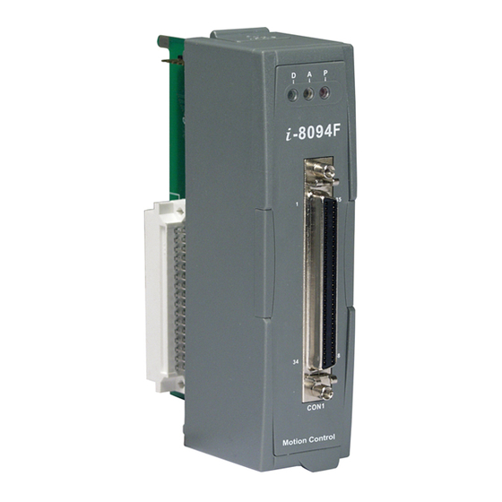
A.2 I8094 Surface http:/www.icpdas.com I8094Getting Started ManualVer.2.3 2008/4/28... -
Page 69: Dimensions
A.3 Dimensions http:/www.icpdas.com I8094Getting Started ManualVer.2.3 2008/4/28... -
Page 70: The Version Upgrades Note
A.4 The Version Upgrades Note //========= V 1.5.1.1 ================== Changed the FUNCTION section Add section 3.9 Synchronization Motion //========= V 1.4.0.1 ================== i8094_* ==>i8094MF_* (All Macro Function) i8094_MF.DLL ==>i8094.DLL i8094_MF.h ==>i8094.h i8094_MF_NET.DLL ==>i8094_NET.DLL i8094 Macro Function Manual ==> Getting Start manual of i8094 motion controlmodule Demo_First Changed(eVC++ and VB.NET) Add section 5.1 Setup the Development Environment of I8094... -
Page 71: Appendix-B Others Terminal Boards
APPENDIX-B Others Terminal Boards B.1 DN-8468M Daughter Board The DN-8468M is the daughter board for Mitsubitch J2 Series Amplifier. It has 4-axis I/O signals. B.1.1 Board Layout for DN-8468M 107mm JP4 JP3 DN-8468M Fig. 1-1 Board layout for the DN-8468M http:/www.icpdas.com I8094Getting Started ManualVer.2.3 2008/4/28... -
Page 72: Signal Connections For Dn-8468M
The I/O connector on the DN-8468M is a 68-pin SCSI II connector that enables you to connect to the I-8094/I8094F motion card. Please refer to the section 2.2.2( page 14). The connector TB1 is 7-pin connector that enables you to connect to the signals of your motor drivers. - Page 73 Table 1-5 TB2 Signal Connection Fig. 1-4 Pin definition for TB2 CN-XA, CN-YA, CN-ZA, CN-UA (CNA connector for each AXIS ) The connectors CN-XA, CN-YA, CN-ZA, and CN-UA are 20-pin connectors that enable you to connect to the CNA connector of Mitsubishi motor drivers. Fig.1-5 shows the pin assignment for the 20-pin connector on the DN-8468M, and the Table 1-6 shows its I/O connector signal description.
- Page 74 CN-XB, CN-YB, CN-ZB, CN-UB (CNB connector for each AXIS ) The connectors CN-XB, CN-YB, CN-ZB, and CN-UB are 20-pin connectors that enable you to connect to the CNB connector of your motor drivers. Fig.1-6 shows the pin assignment for the 20-pin connector on the DN-8468M, and the Table 1-7 shows its I/O connector signal description.
- Page 75 CN5~CN8 (The I/O signals of the X, Y, Z, U AXIS ) The connectors CN5~CN8 are 15-pin connectors that enable users to connect the signals to external motor drivers. Fig.1-8 shows the pin assignment for the 15-pin connector on the DN-8468M, and the Table 1-9 shows its I/O connector signal description.
-
Page 76: Jumper And Switch Settings
RJ1 (The I/O signals of the FRnet) The connectors RJ1 is an 8-pin RJ45 connector that enable you to connect to the signals of FRnet. Fig.1-9 shows the pin assignment for the 8-pin connector on the DN-8468M, and the Table 1-10 shows its I/O connector signal description. Fig. - Page 77 Fig. 1-11 Primary encoder signals setting Fig. 1-12 External encoder signals setting EMG SW The emergency stop signal for each servo ampilfier can be selected from EMG SW. The number 1, 2 , 3, 4 on EMG SW are denoted as axis X, Y, Z, U, respectively. Fig. 1-13 is the default setting to connect the EMG singals to GND.
-
Page 78: Dn-8468P Daughter Board
B.2 DN-8468P Daughter Board The DN-8468P is the daughter board for Panasonic A4 Series Ampilifier. It has 4-axis I/O signals. B.2.1 Board Layout for DN-8468P 107mm JP4 JP3 DN-8468P Fig. 1-1 Board layout for the DN-8468P http:/www.icpdas.com I8094Getting Started ManualVer.2.0 2007/6/28... -
Page 79: Signal Connections For Dn-8468P
The I/O connector on the DN-8468P is a 68-pin SCSI II connector that enables you to connect to the I-8094/I8094F motion card. Please refer to the section 2.2.2( page 14). The connector TB1 is 7-pin connector that enables you to connect to the signals of your motor drivers. - Page 80 CNX, CNY, CNZ, CNU (CN X5 connector for each AXIS in Driver) The connectors CNX, CNY, CNZ, and CNU are 50-pin connectors that enable you to connect to the CN X5 connector of Panasonic motor drivers. Fig.1-5 shows the pin assignment for the 50-pin connector on the DN-8468P, and the Table 1-6 shows its I/O connector signal description.
- Page 81 CN1~CN4 (The I/O signals of the X, Y, Z, U AXIS ) The connectors CN1~CN4 are 11-pin connectors that enable you to connect to the signals of your motor drivers. Fig.1-7 shows the pin assignment for the 20-pin connector on the DN-8468P, and the Table 1-8 shows its I/O connector signal description.
- Page 82 Note 1: There are two sets encoder signals for X and Y axes. In X axis, one is from CNX and the other is from CN5. In Y axis, one is from CNY and the other is from CN6. Users can select encoder signals from JP1 and JP2, respectively. Note 2: In Z and U axes, only one set of encoder signals is used for each axis.
-
Page 83: Jumper And Switch Settings
B.2.3 Jumper and Switch Settings Jumper 5 controls the EMG-A signal of the TB1 connector. The following diagram is shown the selection condition of the jumper 5. Fig. 1-10 Jumper 5 setting JP1, JP2 The encoder signals of axis X and axis Y can be chosen from servo driver encoder or external encoder. - Page 84 EMG SW The emergency stop signal for each servo ampilfier can be selected from EMG SW. The number 1, 2 , 3, 4 on EMG SW are denoted as axis X, Y, Z, U, respectively. Fig. 1-13 is the default setting to connect the EMG singals to GND. The EMG signals from CN1 ~ CN4 will not take effect.
-
Page 85: Dn-8486Y Daughter Board
B.3 DN-8486Y Daughter Board The DN-8468Y is the daughter board for Yaskawa Ampilifier. It has 4-axis I/O signals. B.3.1 Board Layout for DN-8468Y 107mm JP4 JP3 DN-8468Y Fig. 3-1 Board layout for the DN-8468Y http:/www.icpdas.com I8094Getting Started ManualVer.2.3 2008/4/28... -
Page 86: Signal Connections For Dn-8468Y
The I/O connector on the DN-8468Y is a 68-pin SCSI II connector that enables you to connect to the I-8094/I8094F motion card. Please refer to the section 2.2.2( page 14). The connector TB1 is 7-pin connector that enables you to connect to the signals of your motor drivers. - Page 87 CNX, CNY, CNZ, CNU (CN X5 connector for each AXIS in Driver) The connectors CNX, CNY, CNZ, and CNU are 50-pin connectors that enable you to connect to the CN X5 connector of Panasonic motor drivers. Fig.3-5 shows the pin assignment for the 50-pin connector on the DN-8468Y, and the Table 3-6 shows its I/O connector signal description.
- Page 88 CN1~CN4 (The I/O signals of the X, Y, Z, U AXIS ) The connectors CN1~CN4 are 11-pin connectors that enable you to connect to the signals of your motor drivers. Fig.3-7 shows the pin assignment for the 20-pin connector on the DN-8468Y, and the Table 3-8 shows its I/O connector signal description.
- Page 89 RJ1 (The I/O signals of the FRnet) The connectors RJ1 is an 8-pin RJ45 connector that enable you to connect to the signals of FRnet. Fig.3-9 shows the pin assignment for the 8-pin connector on the DN-8468Y, and the Table 3-10 shows its I/O connector signal description. http:/www.icpdas.com I8094Getting Started ManualVer.2.3 2008/4/28...
-
Page 90: Jumper And Switch Settings
B.3.3 Jumper and Switch Settings Jumper 5 controls the EMG-A signal of the TB1 connector. The following diagram is shown the selection condition of the jumper 5. Fig. 3-10 Jumper 5 setting JP1, JP2 The encoder signals of axis X and axis Y can be chosen from servo driver encoder or external encoder. - Page 91 Fig. 3-11 Primary encoder signals setting Fig. 3-12 External encoder signals setting EMG SW The emergency stop signal for each servo ampilfier can be selected from EMG SW. The number 1, 2 , 3, 4 on EMG SW are denoted as axis X, Y, Z, U, respectively. Fig. 3-13 is the default setting to connect the EMG singals to GND.
-
Page 92: Dn-8468D Daughter Board
Fig. 3-14 EMG SW setting for user controlled signals. B.4 DN-8468D Daughter Board The DN-8468D is the daughter board for Delta ASDA-A Series Ampilifier. It has 4-axis I/O signals. B4.1 Board Layout for DN-8468D http:/www.icpdas.com I8094Getting Started ManualVer.2.3 2008/4/28... - Page 93 107mm JP4 JP3 DN-8468D Fig. 3-1 Board layout for the DN-8468D http:/www.icpdas.com I8094Getting Started ManualVer.2.3 2008/4/28...
-
Page 94: B4.2 Signal Connections For Dn-8468D
The I/O connector on the DN-8468D is a 68-pin SCSI II connector that enables you to connect to the I-8094 motion card. Fig. 3-2 shows the pin assignment for the 68-pin I/O connector on the DN-8468D (or on the I-8094), and refer to Table 3-2, 3-3 for description of each motion I/O signal. - Page 95 Table 3-2 DN-8468D I/O connector signal description (part 1) Pin name Pin number Description XECA Encoder A-phase signal for X axis YECA Encoder A-phase signal for Y axis ZECA Encoder A-phase signal for Z axis UECA Encoder A-phase signal for U axis XECB Encoder B-Phase signal for X axis YECB...
- Page 96 Pin name Pin number Description XEXPP EXT pulsar input signal (+) for X axis YEXPP EXT pulsar input signal (+) for Y axis ZEXPP EXT pulsar input signal (+) for Z axis UEXPP EXT pulsar input signal (+) for U axis XEXPM EXT pulsar input signal (-) for X axis YEXPM...
- Page 97 The connector TB1 is 7-pin connector that enables you to connect to the signals of your motor drivers. Fig.3-3 shows the pin assignment for the 7-pin connector on the DN-8468D, and the Table 3-4 shows its I/O connector signal description. The connector TB2 is 5-pin connector that enables you to connect to the signals of your motor drivers.
- Page 98 CNX, CNY, CNZ, CNU (CN 1 connector for each AXIS in Driver) The connectors CNX, CNY, CNZ, and CNU are 50-pin connectors that enable you to connect to the CN1 connector of Delta ASDA-A series motor drivers. Fig.3-5 shows the pin assignment for the 50-pin connector on the DN-8468D, and the Table 3-6 shows its I/O connector signal description.
- Page 99 CN1~CN4 (The I/O signals of the X, Y, Z, U AXIS ) The connectors CN1~CN4 are 11-pin connectors that enable you to connect to the signals of your motor drivers. Fig.3-7 shows the pin assignment for the 20-pin connector on the DN-8468D, and the Table 3-8 shows its I/O connector signal description.
- Page 100 CN5~CN8 (The I/O signals of the X, Y, Z, U AXIS ) The connectors CN5~CN8 are 15-pin connectors that enable users to connect the signals to external motor drivers. Fig.3-8 shows the pin assignment for the 15-pin connector on the DN-8468D, and the Table 3-9 shows its I/O connector signal description.
- Page 101 RJ1 (The I/O signals of the FRnet) The connectors RJ1 is an 8-pin RJ45 connector that enable you to connect to the signals of FRnet. Fig.3-9 shows the pin assignment for the 8-pin connector on the DN-8468D, and the Table 3-10 shows its I/O connector signal description. http:/www.icpdas.com I8094Getting Started ManualVer.2.3 2008/4/28...
-
Page 102: B4.3 Jumper And Switch Settings
B4.3 Jumper and Switch Settings Jumper 5 controls the EMG-A signal of the TB1 connector. The following diagram is shown the selection condition of the jumper 5. Fig. 3-10 Jumper 5 setting JP1, JP2 The encoder signals of axis X and axis Y can be chosen from servo driver encoder or external encoder. - Page 103 The emergency stop signal for each servo ampilfier can be selected from SW1. The number 1, 2 , 3, 4 on SW1 are denoted as axis X, Y, Z, U, respectively. Fig. 3-13 is the default setting to connect the EMG singals to GND. The EMG signals from CN1 ~ CN4 will not take effect. If the switch is disconnected as shown in Fig.
Need help?
Do you have a question about the I-8094 and is the answer not in the manual?
Questions and answers