Table of Contents
Advertisement
Quick Links
Advertisement
Table of Contents

Related Manuals for ICP DAS USA IR-310-RM


Summary of Contents for ICP DAS USA IR-310-RM
- Page 1 ГК Атлант Инжиниринг – официальный представитель в РФ и СНГ +7(495)109-02-08 sales@bbrc.ru www.bbrc.ru IR-310-RM IR Controlled 10-ch High Power Relay Module User Manual v1.1 www.icpdas.com IR-310-RM, IR Controlled 10-ch High Power Relay Module (Ver. 1.1, Jul/02/2013) 1...
- Page 2 Copyright Copyright 2013 by ICP DAS. All rights are reserved. Trademark The names used for identification only may be registered trademarks of their respective companies. IR-310-RM, IR Controlled 10-ch High Power Relay Module (Ver. 1.1, Jul/02/2013) 2...
-
Page 3: Table Of Contents
Emit IR Commands section ........................ 26 4.2.9 Relay States Settings Corresponding to IR Cmds ................27 MODBUS COMMANDS FOR IR-310-RM ..................... 29 FC01 (0 01) R ........................... 30 OILS IR-310-RM, IR Controlled 10-ch High Power Relay Module (Ver. 1.1, Jul/02/2013) 3... - Page 4 5.4.25 Sub-FC 75 (0x4B): Set relay pairs for interlocked mode ............... 58 5.4.26 Sub-FC 76 (0x4C): Read the DIP switch state ..................59 5.4.27 Sub-FC 90 (0x5A): Emit IR remote commands for the IR-310-RM ............60 5.4.28 Sub-FC 91 (0x5B) Set Forward/Backward sequential action ..............61 TECHNICAL SUPPORT ..........................
-
Page 5: Introduction
+7(495)109-02-08 sales@bbrc.ru www.bbrc.ru 1. Introduction IR-310-RM is a 10-channel high power relay module designed for the power switching control of the appliances. The relay module can switch up to 10 A loads. There are NO/NC contacts and protection circuit for each channel. The channels can be controlled independently or sequentially by serial communication with Modbus RTU protocol, as well as by wireless IR remote control. -
Page 6: Features
Modbus Network IDs: 1 ~ 15 (HW); 1 ~ 247 (SW). [IR Utility] IR utility is a configuration tool for the IR series modules of ICP DAS. IR-310-RM utility, as a part of the IR utility, has functions as follows: ... -
Page 7: Hardware
Operating Temperature -25 to +75°C Storage Temperature -30 to 80°C Humidity 10 to 90%, non-condensing Mechanism Dimensions(W x H x D) 220 mm x 48 mm x 113 mm IR-310-RM, IR Controlled 10-ch High Power Relay Module (Ver. 1.1, Jul/02/2013) 7... -
Page 8: Appearance
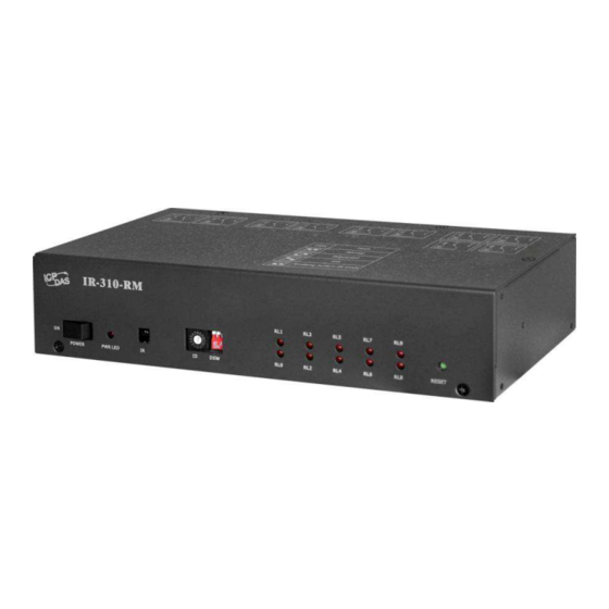
ГК Атлант Инжиниринг – официальный представитель в РФ и СНГ +7(495)109-02-08 sales@bbrc.ru www.bbrc.ru 2.2 Appearance Front Rear Figure 2-1: Front, top and rear view of IR-310-RM. IR-310-RM, IR Controlled 10-ch High Power Relay Module (Ver. 1.1, Jul/02/2013) 8... -
Page 9: Pin Assignments
IR Output: 3.5 mm audio jack for the IR emitter cable CA-IR-SH2251-5. 3. Communication terminal Table 2-2: Pin assignments of serial port Serial port DATA+ RS-485 DATA- RS-232 IR-310-RM, IR Controlled 10-ch High Power Relay Module (Ver. 1.1, Jul/02/2013) 9... -
Page 10: Wire Connection
The accompanied cable CA-0910 can be used for the RS-232 connection to the IR- 310-RM. The RS-232 connection using CA-0910 is shown in Figure 2-6. Figure 2-5: RS-232 connection cable (CA-0910) IR-310-RM, IR Controlled 10-ch High Power Relay Module (Ver. 1.1, Jul/02/2013) 10... -
Page 11: Rs-485 Connection
+7(495)109-02-08 sales@bbrc.ru www.bbrc.ru Figure 2-6: The RS-232 connection using CA-0910 2.4.2 RS-485 connection The RS-485 connection between IR-310-RM and RS-485 host device is shown in the figure 2-7. Figure 2-7: RS-485 connection IR-310-RM, IR Controlled 10-ch High Power Relay Module (Ver. 1.1, Jul/02/2013) 11... -
Page 12: Relay Terminal
The IR-310-RM only supports +12 V . FRA05-S12-SU is a recommended power supply with a DC connector which supplys 12 V /max.0.58A. Figure 2-10: DC power jack for +12 V IR-310-RM, IR Controlled 10-ch High Power Relay Module (Ver. 1.1, Jul/02/2013) 12... -
Page 13: Watchdog Setting
The watchdog is a timer to reset the hung system due to some fault conditions. The watchdog of the IR-310-RM can be enabled or disabled by JP1 as shown in Figure 2- 11. It is necessary to open the case to set JP1. The watchdog is enabled by default. -
Page 14: Jumper For Firmware Update
ГК Атлант Инжиниринг – официальный представитель в РФ и СНГ +7(495)109-02-08 sales@bbrc.ru www.bbrc.ru Jumper for Firmware Update There is a jumper JP5 in the case of IR-310-RM for setting the operation mode (OP) or Firmware update mode (FW). Figure 2-12: JP5 setting for Firmware Update 2.6.1 Update firmware mode... -
Page 15: Normal Operation Mode
Firmware_Update_Tool can be downloaded from: ftp://ftp.icpdas.com/pub/cd/usbcd/napdos/ir-310-rm/software/fw_update_tool/ 2.6.2 Normal Operation Mode Set the JP5 to the “OP” in figure 2-11 and power cycle the IR-310-RM to enable the Normal Operation Mode. IR-310-RM, IR Controlled 10-ch High Power Relay Module (Ver. 1.1, Jul/02/2013) 15... -
Page 16: Led Indicators
ГК Атлант Инжиниринг – официальный представитель в РФ и СНГ +7(495)109-02-08 sales@bbrc.ru www.bbrc.ru 2.7 LED Indicators There are two kinds of LEDs for IR-310-RM to indicate several states. (1) Power LED : The PWR LED is ON to indicate the IR-310-RM is turned on. -
Page 17: Dip Switch
+7(495)109-02-08 sales@bbrc.ru www.bbrc.ru 2.8 DIP Switch There four states of the 2-pin dip switch which represent four modes for IR-310-RM as shown in table 2-5. To take effect the setting, please power cycle the module after set the dip switch. - Page 18 ГК Атлант Инжиниринг – официальный представитель в РФ и СНГ +7(495)109-02-08 sales@bbrc.ru www.bbrc.ru Figure 2-16: The flowchart of emitting built-in IR commands Figure 2-17: Use IR learning remote to learn IR commands. IR-310-RM, IR Controlled 10-ch High Power Relay Module (Ver. 1.1, Jul/02/2013) 18...
-
Page 19: Configuration And Control On Ir-310-Rm
Modbus/RTU commands for the Modbus master. Please refer to chapter 4 and 5 to learn the IR-310-RM utility and the Modbus commands. IR-310-RM, IR Controlled 10-ch High Power Relay Module (Ver. 1.1, Jul/02/2013) 19... -
Page 20: Configuration Utility
Standalone Installer http://www.microsoft.com/download/en/details.aspx?id=24872 IR-310-RM Utility is a part of the IR Utility. Please select the “IR-310-RM” item in the Module combobox and click the “Connect/Open Interface” button to get the IR-310-RM utility. Figure 4-1: The main window of IR Utility with the IR-310-RM selected. -
Page 21: Ir-310-Rm Utility
IR-310-RM Utility 4.2.1 Main Window of IR-310-RM Utility IR-310-RM Utility is a part of the IR Utility. IR-310-RM Utility gives an easy interface to configure IR-310-RM. Users can also refer to chapter 5 for the control and settings on IR-310-RM by the Modbus commands. - Page 22 Save all settings buffered in the IR-310-RM utility to a file with the filename extension “.ird”. ‧Load Settings from File Load all settings from the ird file of IR-310-RM and put them in the IR-310-RM utility. ‧Close IR-310-RM Utility Close IR-310-RM utility and back to the main window of IR utility.
-
Page 23: Relay Output Section
‧Load Settings from IR-310-RM When the communication connection is established, utility does not load settings from IR-310-RM. Users have to click “get” buttons to get setting values in each section or click this menu item to load all setting values from IR-310-RM. -
Page 24: Communication Settings Section
(ms) for sequential action of relays after clicking the get buttons. The range of the time interval is 0 to 65535 ms. Figure 4-6: Settings of sequential relay action. IR-310-RM, IR Controlled 10-ch High Power Relay Module (Ver. 1.1, Jul/02/2013) 24... -
Page 25: Power On Value And Power Failure Memory Section
+7(495)109-02-08 sales@bbrc.ru www.bbrc.ru 4.2.6 Power on value and power failure memory section If the “Enable Power Failure Memory” is not set, IR-310-RM applies the Power On Value settings of 10 relay states. Otherwise, the 10 relay states of power failure memory are used when power is on. -
Page 26: Emit Ir Commands Section
IR-310-RM. Click the “Emit IR Command” button will emit an IR command. Users can aim the head of the IR emitter cable to the IR receiver of the IR-310-RM for test. This function is for the IR learning remote to learn the IR commands for the IR-310-RM module. -
Page 27: Relay States Settings Corresponding To Ir Cmds
Set the IR-relay-state for the item of the IR cmd No combobox to the connected IR- 310-RM. ‧ Get button Get the IR-relay-state for the item of the IR cmd No combobox from the connected IR-310-RM. IR-310-RM, IR Controlled 10-ch High Power Relay Module (Ver. 1.1, Jul/02/2013) 27... - Page 28 ‧ Set All button Equivalent to Menu [Settings] => [Download Settings to IR-310-RM]=>[Only IR- Relay-States]. ‧ Get All button Equivalent to Menu [Settings] => [Load Settings from IR-310-RM]=>[Only IR-Relay- States]. IR-310-RM, IR Controlled 10-ch High Power Relay Module (Ver. 1.1, Jul/02/2013) 28...
-
Page 29: Modbus Commands For Ir-310-Rm
5. Modbus Commands for IR-310-RM The following Function Code commands are provided for a Modbus master to control and configure IR-310-RM. It is necessary to append 2 bytes of CRC16 to the tail of each Modbus command. FC01, 05, and 15 are the standard Modbus commands for Modbus masters to access the relay outputs of IR-310-RM. -
Page 30: 01) Read Coils
02: Byte count is 2. 10 relay states need 2 bytes to get back the states. D5 00: Relay status. D5 is the low byte for RL0 to RL7. 00 is the high byte for RL8 and RL9. IR-310-RM, IR Controlled 10-ch High Power Relay Module (Ver. 1.1, Jul/02/2013) 30... -
Page 31: Coil
Request (hex): 01 05 00 08 FF 00 0D F8 (“0D F8” is CRC16) Response (hex): 01 05 00 08 FF 00 0D F8 (“0D F8” is CRC16) IR-310-RM, IR Controlled 10-ch High Power Relay Module (Ver. 1.1, Jul/02/2013) 31... -
Page 32: Write Multiple Coils
Request (hex): 01 05 00 08 FF 00 0D F8 (“0D F8” is CRC16) Response (hex): 01 05 00 08 FF 00 0D F8 (“0D F8” is CRC16) IR-310-RM, IR Controlled 10-ch High Power Relay Module (Ver. 1.1, Jul/02/2013) 32... -
Page 33: 64) Read /Write Module Settings
5.4 FC100 (0x64) Read/Write Module Settings This section describes all sub function calls (sub-FC) of FC100 (0x64) for the settings on IR-310-RM. It is necessary to append 2 bytes of CRC16 to the tail of each Modbus command. Table 5-2: Sub-FCs of FC100 for IR-310-RM... -
Page 34: Sub-Fc 00 (0X00): Read Module Name
Address 1 Byte 1 ~ 247 1 Byte 0x64 Sub-FC 1 Byte 0x00 03~14 Module 12 Bytes Hex ASCII code of characters. 0x00 is none. “IR310RM”=> name 0x49,0x52,0x33,0x31,0x30,0x52,0x4D IR-310-RM, IR Controlled 10-ch High Power Relay Module (Ver. 1.1, Jul/02/2013) 34... -
Page 35: Sub-Fc 03 (0X03): Get The Software Modbus Address Of The Module
2. Rotary switch position 0x00 is for software Modbus address (Net ID) = 1 ~ 247. 3. If hardware Modbus addresses are applied, software Modbus addresses are ineffective. IR-310-RM, IR Controlled 10-ch High Power Relay Module (Ver. 1.1, Jul/02/2013) 35... -
Page 36: Sub-Fc 04 (0X04): Set The Software Modbus Address Of The Module
2. Rotary switch position 0x00 is for software Modbus address (Net ID) = 1 ~ 247 configured by this Sub-FC. 3. The priority of the hardware Modbus addresses are higher than that of software Modbus addresses. IR-310-RM, IR Controlled 10-ch High Power Relay Module (Ver. 1.1, Jul/02/2013) 36... -
Page 37: Sub-Fc 05 (0X05) Read The Communication Settings
1 Byte Index = 3 ~ 10 3=>1200 bps, 4=>2400, 5=>4800, 6=>9600, 7=>19200, 8=>38400, 9=>57600, 10=>115200 Reserved 1 Byte 0x00 Reserved 1 Byte 0x00 Reserved 1 Byte 0x00 IR-310-RM, IR Controlled 10-ch High Power Relay Module (Ver. 1.1, Jul/02/2013) 37... -
Page 38: Sub-Fc 06 (0X06): Set The Communication Settings
1 ~ 247 1 Byte 0x64 Sub-FC 1 Byte 0x06 Baud rate 1 Byte 0=>OK, 0xFF=>error Reserved 1 Byte 0x00 Reserved 1 Byte 0x00 Reserved 1 Byte 0x00 IR-310-RM, IR Controlled 10-ch High Power Relay Module (Ver. 1.1, Jul/02/2013) 38... -
Page 39: Sub-Fc 07 (0X07): Read Module Response Delay Time
Description Size Value Address 1 Byte 1 ~ 247 1 Byte 0x64 Sub-FC 1 Byte 0x07 MB resp. 1 Byte 0 ~ 60 ms, default: 1ms delay time IR-310-RM, IR Controlled 10-ch High Power Relay Module (Ver. 1.1, Jul/02/2013) 39... -
Page 40: Sub-Fc 08 (0X08): Set Module Response Delay Time
‧Response Byte order Description Size Value Address 1 Byte 1 ~ 247 1 Byte 0x64 Sub-FC 1 Byte 0x08 MB resp. 1 Byte 0=>OK, 0xFF=>error delay time IR-310-RM, IR Controlled 10-ch High Power Relay Module (Ver. 1.1, Jul/02/2013) 40... -
Page 41: Sub-Fc 32 (0X20): Read The Firmware Version
1 Byte 0x64 Sub-FC 1 Byte 0x20 Major Ver. 1 Byte 0x00 ~ 0xFF Minor Ver. 1 Byte 0x00 ~ 0xFF Build Ver. 1 Byte 0x00 ~ 0xFF IR-310-RM, IR Controlled 10-ch High Power Relay Module (Ver. 1.1, Jul/02/2013) 41... -
Page 42: Sub-Fc 35 (0X23): Read Power-On Value/Power Failure Memory Mode
This is useful for some application such as lighting control after the power restoration. One of the two modes used by IR-310-RM can be read by this sub-FC. Only one of the two modes can be used at the same time. -
Page 43: Sub-Fc 36 (0X24): Set Power-On Value/Power Failure Memory Mode
This is useful for some application such as lighting control after the power restoration. Only one of the two modes can be set to IR-310-RM by this sub-FC. ‧Request... -
Page 44: Sub-Fc 37 (0X25): Read The Latency For Power Failure Memory
+7(495)109-02-08 sales@bbrc.ru www.bbrc.ru 5.4.11 Sub-FC 37 (0x25): Read the latency for power failure memory As soon as the relay states changed, IR-310-RM will record the 10 relay states until the PFM latency (ms) passed. Read the PFM latency by the following command. -
Page 45: Sub-Fc 38 (0X26): Set The Latency For Power Failure Memory
+7(495)109-02-08 sales@bbrc.ru www.bbrc.ru 5.4.12 Sub-FC 38 (0x26): Set the latency for power failure memory As soon as the relay states changed, IR-310-RM will record the 10 relay states until the PFM latency (ms) passed. Set the PFM latency by the following command. -
Page 46: Sub-Fc 39 (0X27): Read The Preset Power-On Values
Bit# = 1 => Relay# is ON (at NO contact) Bit# = 0 => Relay# is OFF (at NC contact) 2. Sequential action” is only effective in sequential mode. IR-310-RM, IR Controlled 10-ch High Power Relay Module (Ver. 1.1, Jul/02/2013) 46... -
Page 47: Sub-Fc 40 (0X28): Set The Preset Power-On Values
Bit# = 1 => Relay# is ON (at NO contact) Bit# = 0 => Relay# is OFF (at NC contact) 2. Sequential action” is only effective in sequential mode. IR-310-RM, IR Controlled 10-ch High Power Relay Module (Ver. 1.1, Jul/02/2013) 47... -
Page 48: Sub-Fc 64 (0X40): Read The Time Interval Of The Sequential Mode
1 Byte 0x00~0xFF. byte1 (MSB) Reserved 1 Byte 0x00 Reserved 1 Byte 0x00 Note: 1. The range of the “Time interval” is 0 ~ 65535 ms. (0x0000 ~ 0xFFFF) IR-310-RM, IR Controlled 10-ch High Power Relay Module (Ver. 1.1, Jul/02/2013) 48... -
Page 49: Sub-Fc 65 (0X41): Set The Time Interval In The Sequential Mode
1 Byte 0x64 Sub-FC 1 Byte 0x41 Setting result 1 Byte 0=>OK, 0xFF=>error Note: 1. The range of the “Time interval” is 0 ~ 65535 ms. (0x0000 ~ 0xFFFF) IR-310-RM, IR Controlled 10-ch High Power Relay Module (Ver. 1.1, Jul/02/2013) 49... -
Page 50: Sub-Fc 66 (0X42): Read The Independent/Interlocked Mode
2. For an interlocked relay pair, e.g. RL0 and RL1, three statuses are allowed: Interlocked Status Relay 0 Relay 1 ON (NO contact) OFF (NC contact) OFF (NC contact) ON (NO contact) OFF (NC contact) OFF (NC contact) IR-310-RM, IR Controlled 10-ch High Power Relay Module (Ver. 1.1, Jul/02/2013) 50... -
Page 51: Sub-Fc 67 (0X43): Set The Independent/Interlocked Mode
2. For an interlocked relay pair, e.g. RL0 and RL1, three statuses are allowed: Interlocked Status Relay 0 Relay 1 ON (NO contact) OFF (NC contact) OFF (NC contact) ON (NO contact) OFF (NC contact) OFF (NC contact) IR-310-RM, IR Controlled 10-ch High Power Relay Module (Ver. 1.1, Jul/02/2013) 51... -
Page 52: Sub-Fc 68 (0X44): Read Ir-Relay-States
(the rightest) is RL0 and the most significant bit# is RL9. Bit# = 1 => Relay# is ON (at NO contact) Bit# = 0 => Relay# is OFF (at NC contact) IR-310-RM, IR Controlled 10-ch High Power Relay Module (Ver. 1.1, Jul/02/2013) 52... -
Page 53: Sub-Fc 69 (0X45): Set Ir-Relay-States
(the rightest) is RL0 and the most significant bit# is RL9. Bit# = 1 => Relay# is ON (at NO contact) Bit# = 0 => Relay# is OFF (at NC contact) IR-310-RM, IR Controlled 10-ch High Power Relay Module (Ver. 1.1, Jul/02/2013) 53... -
Page 54: Sub-Fc 70 (0X46): Read The Source Of Ir Sensor
1 ~ 247 1 Byte 0x64 Sub-FC 1 Byte 0x46 Source of the 1 Byte 0 => None, IR sensor 1 => Onboard IR receiver, 2 => IR receiver cable. IR-310-RM, IR Controlled 10-ch High Power Relay Module (Ver. 1.1, Jul/02/2013) 54... -
Page 55: Sub-Fc 71 (0X47): Set The Source Of Ir Sensor
Byte order Description Size Value Address 1 Byte 1 ~ 247 1 Byte 0x64 Sub-FC 1 Byte 0x47 Setting result 1 Byte 0 => OK, Others => Error IR-310-RM, IR Controlled 10-ch High Power Relay Module (Ver. 1.1, Jul/02/2013) 55... -
Page 56: Sub-Fc 72 (0X48): Read Non-Sequential/Sequential Mode
Sub-FC 1 Byte 0x48 ‧Response Byte order Description Size Value Address 1 Byte 1 ~ 247 1 Byte 0x64 Sub-FC 1 Byte 0x48 Mode 1 Byte 0=>Non-sequential, 1=>Sequential. IR-310-RM, IR Controlled 10-ch High Power Relay Module (Ver. 1.1, Jul/02/2013) 56... -
Page 57: Sub-Fc 74 (0X4A): Read Relay Pairs For Interlocked Mode
3. For an interlocked relay pair, e.g. RL0 and RL1, three statuses are allowed: Interlocked Status Relay 0 Relay 1 ON (NO contact) OFF (NC contact) OFF (NC contact) ON (NO contact) OFF (NC contact) OFF (NC contact) IR-310-RM, IR Controlled 10-ch High Power Relay Module (Ver. 1.1, Jul/02/2013) 57... -
Page 58: Sub-Fc 75 (0X4B): Set Relay Pairs For Interlocked Mode
3. For an interlocked relay pair, e.g. RL0 and RL1, three statuses are allowed: Interlocked Status Relay 0 Relay 1 ON (NO contact) OFF (NC contact) OFF (NC contact) ON (NO contact) OFF (NC contact) OFF (NC contact) IR-310-RM, IR Controlled 10-ch High Power Relay Module (Ver. 1.1, Jul/02/2013) 58... -
Page 59: Sub-Fc 76 (0X4C): Read The Dip Switch State
1 Byte 0x00 ~ 0x03. Note: 1. DIP switch state values: DIP switch state values Mode Normal Sequential Init Auto-emitting 12 built-in IR commands (IR cmd# 192 ~ 203) IR-310-RM, IR Controlled 10-ch High Power Relay Module (Ver. 1.1, Jul/02/2013) 59... -
Page 60: Sub-Fc 90 (0X5A): Emit Ir Remote Commands For The Ir-310-Rm
3. Two IR commands with the same IR cmd number but different Modbus Addresses (Net ID) are different commands which can only control the IR-310pRM with the same Modbus address. IR-310-RM, IR Controlled 10-ch High Power Relay Module (Ver. 1.1, Jul/02/2013) 60... -
Page 61: Sub-Fc 91 (0X5B) Set Forward/Backward Sequential Action
1 ~ 247 1 Byte 0x64 Sub-FC 1 Byte 0x5B Setting 1 Byte 0x00 => OK, 0xFF=>Error. result Note: 1. This sub-FC is only effective in the sequential mode. IR-310-RM, IR Controlled 10-ch High Power Relay Module (Ver. 1.1, Jul/02/2013) 61... -
Page 62: Technical Support
ГК Атлант Инжиниринг – официальный представитель в РФ и СНГ +7(495)109-02-08 sales@bbrc.ru www.bbrc.ru Technical support Please contact us if you have any questions about products. ICP DAS website: http://www.icpdas.com Email: service@icpdas.com IR-310-RM, IR Controlled 10-ch High Power Relay Module (Ver. 1.1, Jul/02/2013) 62... -
Page 63: Appendix A: Built-In Ir-Relay-States
RL7 ON (others not influenced) RL7 OFF (others not influenced) RL8 ON (others not influenced) RL8 OFF (others not influenced) RL9 ON (others not influenced) RL9 OFF (others not influenced) IR-310-RM, IR Controlled 10-ch High Power Relay Module (Ver. 1.1, Jul/02/2013) 63... -
Page 64: Appendix B: Init Mode
In this mode, IR-310-RM applies the default communication settings. Table B-1 Table B-1: Default communication settings Item Default value Baud Rate 9600 bps Parity/Databits/Stopbtis None/8/1 Modbus Net ID 1 (RSW ID = 1) IR-310-RM, IR Controlled 10-ch High Power Relay Module (Ver. 1.1, Jul/02/2013) 64... -
Page 65: Appendix C: Rack And Wall Mounting
The steel joint plate is for joining two IR-310-RMs as a length of 19“ (1U). Wall Mounting The two wall mount brackets in the package are installed on the case as follows. IR-310-RM, IR Controlled 10-ch High Power Relay Module (Ver. 1.1, Jul/02/2013) 65...
Need help?
Do you have a question about the IR-310-RM and is the answer not in the manual?
Questions and answers