Otto Bock Dynion 3R85 Instructions For Use Manual
Hide thumbs
Also See for Dynion 3R85:
- Instructions for use manual (400 pages) ,
- Quick reference manual (8 pages)

Related Manuals for Otto Bock Dynion 3R85


Summary of Contents for Otto Bock Dynion 3R85
- Page 1 Dynion 3R85 Instructions for use ......................
-
Page 3: Table Of Contents
Table of contents Notes regarding the document ..................Explanation of warning symbols ................Meanings of pictograms in the illustration ..............Characteristics (product, document) ..............Document versions ....................Product description ....................... Intended use ........................Indications for use ....................Area of application .................... -
Page 4: Notes Regarding The Document
1 Notes regarding the document INFORMATION Date of last update: 2022-05-07 Please read this document carefully before using the product and observe the safety ► notices. Instruct the user in the safe use of the product. ► Please contact the manufacturer if you have questions about the product or in case of prob ►... -
Page 5: Characteristics (Product, Document)
1.3 Characteristics (product, document) : The following characteristics are important for identification: • : 3R85 [product reference number] • : YYYYWWNNNN [product serial number: YYYY (year of manufacture); WW (calendar week); NNNN (number)] • : 647G1166=all_INT-VV-YYMM [standard line for the document: 647G1166=all_INT (refer ence number for the document); VV (version number); YYMM (publication date) – YY (year); MM (month)]... -
Page 6: Document Versions
1.4 Document versions : The document is available in the following versions: • : 647G1166=all_INT (document reference number with all available languages) All illustrations in this document are found at the beginning. They are followed by the texts in all languages. This printed document is included in the scope of delivery. This document is available in electronic form (PDF file). -
Page 7: Product Description
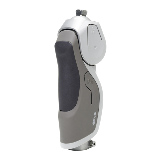
2 Product description The product (3R85) has the following key features: • Monocentric prosthetic knee joint with rotation hydraulics • Product components for stance phase stability: Adjustable stance phase flexion resistance (hydraulic damping) Adjustable switching threshold to deactivate stance phase flexion resistance at the end of the stance phase Modes (switching by the patient): Standard mode –... -
Page 8: Combination Possibilities
3.3 Combination possibilities CAUTION Improper combination of prosthetic components Injuries, malfunctions or product damage due to unallowable combination of prosthesis compo nents Based on the instructions for use of all prosthetic components used, verify that they may be ► combined with each other and are approved for the patient's area of application. INFORMATION In a prosthesis, all prosthetic components have to meet the patient's requirements regarding the amputation level, body weight, activity level, environmental conditions and field of application. -
Page 9: Environmental Conditions
3.4 Environmental conditions CAUTION Use under unallowable environmental conditions Fall due to damaged product Do not expose the product to unallowable environmental conditions (see the table "Unallow ► able environmental conditions" in this section). If the product was exposed to unallowable environmental conditions, take suitable steps ►... -
Page 10: Reuse And Lifetime
3.5 Reuse and lifetime CAUTION Reuse on another patient Fall due to loss of functionality as well as damage to the product Only use the product for a single patient. ► CAUTION Exceeding the lifetime Fall due to change in or loss of functionality and damage to the product Ensure that the maximum lifetime defined in this section is not exceeded. -
Page 11: Scope Of Delivery
5 Scope of delivery : Check the scope of delivery against the illustrations. Only product components with reference numbers in the illustration can be reordered separately. A product component without a reference number in the illustration cannot be reordered separ ately. Reference numbers in brackets "()"... -
Page 12: Technical Data
6 Technical data + : See the illustrations for the technical data. m° 100 kg 1240 g 220 lbs... - Page 13 : Build height; : Proximal build height; : Distal build height; : System height; : Proximal system height; : Distal system height 145° 231 mm Ø 30 mm 44,5 mm 26,5 mm 147 mm 120 mm – – 216,5 mm 160 mm 133 mm 172 mm...
-
Page 14: Preparing The Product For Use
7 Preparing the product for use 7.1 Information on fabrication of a prosthesis CAUTION Incorrect alignment, assembly or adjustment Injury due to incorrectly installed or adjusted as well as damaged prosthetic components Observe the alignment, assembly and adjustment instructions. ► CAUTION Initial use of the prosthesis by the patient Fall due to lack of patient experience, incorrect alignment or incorrect adjustment of the pros... - Page 15 0 mm 5° 5 – 7°...
- Page 16 Use 2Z11=KIT INFORMATION: The connection area of the prosthetic knee joint can be protected against scratches with the protective film of the 2Z11=KIT during alignment in the workshop and testing in the trial fitting area. ► Use the protective film as illustrated in the accompanying document for the 2Z11=KIT. ►...
- Page 17 Installing the tube adapter CAUTION Improper assembly of the screw connections Risk of injury due to breakage or loosening of the screw connections Clean the threads before every installation. ► Apply the specified torque values. ► Follow the instructions for thread lock. ►...
- Page 18 : CAUTION! Position and clamp the tube adapter only as shown in the illustration. ► : Impermissible value: > 13 mm → : Permissible value: 0 – 13 mm → : Recommended value: 0 mm → 704Y14=30 719R4 718R1 >13 mm 0 – 13 mm 0 mm 13 mm LOCTITE 4 mm 10 Nm...
-
Page 19: Optimising The Static Alignment
7.3 Optimising the static alignment INFORMATION: Additional technical knowledge is provided by the instructions for use of the measuring apparatus being used, the TF alignment poster and the Ottobock seminars. The 743L500 3D L.A.S.A.R. Posture measuring apparatus is needed to optimise the static align ment. - Page 20 : : Optimisation with 3D mode activated ► Optimise the static alignment so the patient stands in a relaxed position, the values for the ref erence points shown in the illustration are met and the following points are observed: • : 3D mode is activated (3D symbol – colour: green). Sequence for optimisation in reference to the planes: : Sagittal plane –...
-
Page 21: Optimising During Dynamic Fitting
: : Optimisation with 3D mode deactivated ► Optimise the static alignment so the values for the reference points shown in the illustration are met and the following points are observed: • : 3D mode is deactivated (3D symbol – colour: dark grey). Sequence for optimisation in reference to the planes: : Sagittal plane –... -
Page 22: Overview Of Adjustment Possibilities
7.4.2 Overview of adjustment possibilities : : Stance phase flexion resistance; : Swing phase flexion resistance; : Swing phase extension resistance; : Switching threshold... - Page 23 Stance phase flexion resistance : : Adjustment range; : Decrease stance phase flexion resistance; : Increase stance phase flexion resistance...
- Page 24 Switching threshold : : Adjustment range; : Reduce switching threshold (lower weight required to initiate the swing phase); : Increase switching threshold (higher weight required to initiate the swing phase) INFORMATION: The weight to initiate the swing phase refers to the force used to push the pros thetic knee joint into hyperextension so that the stance phase flexion resistance is deactivated again at the end of the stance phase, and therefore does not slow down or prevent the flexion movement into the swing phase.
- Page 25 Swing phase flexion resistance : : Adjustment range; : Decrease swing phase flexion resistance; : Increase swing phase flexion resistance...
- Page 26 Swing phase extension resistance : : Adjustment range; : Decrease swing phase extension resistance; : Increase swing phase extension resistance...
- Page 27 Lock : Activate the lock as shown in the illustration for use in wet areas (e.g. showering and ► swimming) and relaxed standing. Deactivate the lock for walking. Put weight on the prosthetic knee joint and push against the extension stop when activating and deactivating. : Activate lock →...
- Page 28 Cycling mode : Activate cycling mode as shown in the illustration for cycling and similar movement ► sequences. For normal walking, switch to standard mode by deactivating cycling mode. : Activate cycling mode → INFORMATION: Activate by pushing against the stop beyond an initial resistance. Stance phase flexion resistance is deactivated by activating cycling mode.
-
Page 29: Checking The Initial Settings For The Dynamic Fitting
7.4.3 Checking the initial settings for the dynamic fitting ► Before the dynamic fitting, check the required initial settings listed below and correct any deviations. : : Stance phase flexion resistance; : Switching threshold to initiate the swing phase INFORMATION : When adjusting the switching threshold to initiate the swing phase, it is necessary to first turn back anticlockwise to the stop and then turn clockwise to the specified position. - Page 30 : : Swing phase flexion resistance; : Swing phase extension resistance : : Lock (deactivated); : Stance phase flexion resistance (activated)
-
Page 31: Switching Between The Stance Phase And Swing Phase
7.4.4 Switching between the stance phase and swing phase : : Stance phase flexion resistance deactivated; : Stance phase flexion resistance activ ated : When the forefoot is loaded at the end of the stance phase, the prosthetic joint is pushed into hyperextension. During subsequent initiation of a knee flexion moment, stance phase flexion res istance is deactivated and swing phase flexion resistance is activated. - Page 32 : : Risk of falling – movements can deactivate stance phase flexion resistance ► CAUTION! Avoid the following movements and note the section "Exercises and adjustments" (see page 33): : Hard ground contact in the forefoot area with strong extension (e.g. curb) immediately → followed by knee flexion moment : ...
-
Page 33: Exercises And Adjustments
7.4.5 Exercises and adjustments INFORMATION: As a supplement to this section, the following videos are available for qualified personnel under the QR codes and links provided. Video "Dynion – Adjustments & settings" ("Dynion – Adjustments & settings" – available languages: English) https://youtu.be/ukZ1Q-dgm5A Video "Dynion –... - Page 34 : : Sitting down ► Adjust the stance phase flexion resistance so it provides the patient with adequate safety, yet does not generate excessive resistance.
- Page 35 : : Walking ► CAUTION! Since there is a risk of falling when the switching threshold is not adjusted cor rectly, allow the patient to walk only with safeguards in place. : At the start of the walking exercise, increase the switching threshold so the swing phase ►...
- Page 36 : : Walking down ramps ► Adjust the stance phase flexion resistance so it provides the patient with adequate safety yet does not generate excessive resistance. : During the exercise, also check whether the swing phase extension resistance setting is ► still appropriate and adjust it if necessary. ►...
- Page 37 : : Walking down stairs ► Adjust the stance phase flexion resistance so it provides the patient with adequate safety yet does not generate excessive resistance. ► Set the swing phase extension resistance so that full extension is reached at heel strike if pos sible.
- Page 38 : : Sitting down (repeat for readjustment) ► Check the stance phase flexion resistance for sitting down again and match it with the setting for walking down ramps and stairs.
- Page 39 : : Walking (repeat for readjustment) Since the switching threshold buffer exhibits settlement (especially during the first 10 minutes), it is essential to check again while walking on a level surface whether short, quick steps are still possible or whether the settings have to be readjusted. : Check the swing phase flexion resistance again and, if necessary, adjust it in small incre...
- Page 40 : For the movements shown in the illustration, there is a risk of falling because they may deac tivate the stance phase flexion resistance. ► CAUTION! Provide the patient with support (e.g. parallel bars) and have them carefully test at what load stance phase flexion resistance is deactivated. Then discuss with the patient how these movements can be avoided or supported.
- Page 41 : : Using the lock ► CAUTION! In the exercises, practice the reliable use of the control elements by the patient without mix-ups. Control elements for the patient on the product: • Push buttons to activate and deactivate the lock • Push buttons to activate and deactivate cycling mode Examples of control elements for the patient on optional prosthetic components: •...
- Page 42 : : Cycling ► Practise using cycling mode. Final inspection ► CAUTION! At the end of the exercises and adjustments, check again whether the switching threshold is correctly adjusted while walking at different speeds with sup port (e.g. between parallel bars). ► NOTICE! Reattach the cover on the pros thetic knee joint to protect it.
-
Page 43: Attaching The Cosmetic Cover
7.5 Attaching the cosmetic cover CAUTION Use of highly hygroscopic particles (grease-absorbent substances such as talcum) Risk of injury, damage to the product due to lack of lubrication Do not allow the product to come into contact with highly hygroscopic particles. ►... - Page 44 : Note the following points for attaching the cosmetic cover: ► CAUTION! Prepare the cosmetic cover so it does not cause any serious restrictions in the fol • lowing areas: Flexion movement (example: maximum flexion while kneeling) Safe functioning (example: no unintentional triggering of control elements during move ment) Safe operation (example: easy access to the control elements –...
-
Page 45: Finishing The Prosthesis
7.6 Finishing the prosthesis : CAUTION! To avoid product damage and the risk of falling, finish the prosthesis by repla ► cing set screws that are too short or too long and by tightening all screw connections. In doing so, observe the instructions for use for all prosthetic components regarding installation torque values and thread lock. -
Page 46: Use
8 Use INFORMATION Provide the information in the subsections of this section to the patient. ► 8.1 Information for use CAUTION Overheating of the hydraulics due to increased activity (e.g. extended walking downhill) Burns, injuries caused by falling due to changes in functionality and damage to prosthetic com ponents INFORMATION: If the hydraulics overheat, the stance phase flexion resistance can no ►... - Page 47 Lock the prosthetic knee joint before using the prosthesis in wet areas. ► Adjust the walking speed to the ambient conditions. ► Make sure the lock is not deactivated or activated through unintentional operation. ► On wet surfaces, only use a prosthetic foot with a slip-resistant sole. ►...
-
Page 48: Cleaning
8.2 Cleaning CAUTION Use of unsuitable cleaning agents or disinfectants Impairment of functionality and damage due to incorrect cleaning agents or disinfectants Only clean the product with the approved cleaning agents. ► Only disinfect the product with the approved disinfectants. ►... -
Page 49: Maintenance
9 Maintenance CAUTION Failure to follow the maintenance instructions Risk of injuries due to changes in or loss of functionality and damage to the product Observe the following maintenance instructions. ► ► NOTICE! Do not lubricate and grease the prosthetic joint. ►... -
Page 50: Disposal
: Checking the sacrificial anode The sacrificial anode protects the product against electrochemical corrosion, as it is destroyed rather than the product. ► Instruct the patient to have the prosthesis inspected as soon as possible in case of visible cor rosion (e.g. rust on the set screws that clamp the proximal adapter on the prosthetic knee joint). -
Page 51: Legal Information
11 Legal information All legal conditions are subject to the respective national laws of the country of use and may vary accordingly. 11.1 Liability The manufacturer will only assume liability if the product is used in accordance with the descrip tions and instructions provided in this document. - Page 52 Ottobock SE & Co. KGaA Max-Näder-Straße 15 · 37115 Duderstadt · Germany T +49 5527 848-0 · F +49 5527 848-3360 healthcare@ottobock.de · www.ottobock.com...
Need help?
Do you have a question about the Dynion 3R85 and is the answer not in the manual?
Questions and answers