Table of Contents
Advertisement
Quick Links
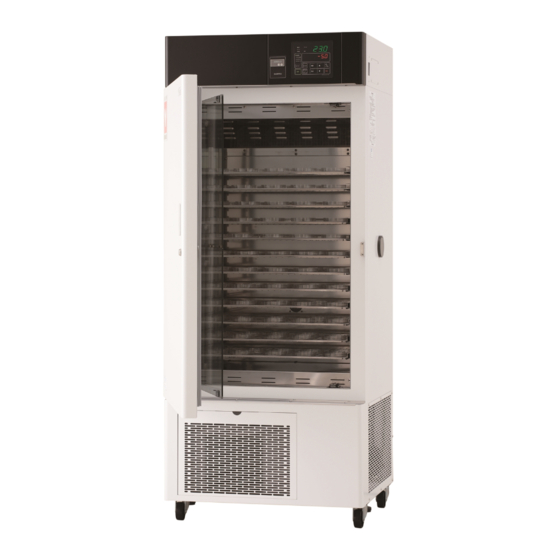
Eco Incubator
Model INE800
First edition
● Thank you very much for purchasing
this Yamato eco incubator INE800.
● Please
Instructions" and "Warranty" before
operating this unit to assure proper
operation.
documents, be sure to store them
securely together with the "Warranty"
at a handy place for future reference.
Warning
: Before operating the unit, be sure
to
understand important warnings in
the operating instructions.
Yamato Scientific Co., Ltd.
read
the
After
reading
read
carefully
This paper has been printed on recycled paper.
"Operating
these
and
fully
Advertisement
Table of Contents

Subscribe to Our Youtube Channel
Related Manuals for Yamato INE800


Summary of Contents for Yamato INE800
- Page 1 Eco Incubator Model INE800 First edition ● Thank you very much for purchasing this Yamato eco incubator INE800. ● Please read “Operating Instructions” and “Warranty” before operating this unit to assure proper operation. After reading these documents, be sure to store them securely together with the “Warranty”...
-
Page 3: Table Of Contents
Contents 1. Safety precautions ........................1 Explanation of pictograms ........................1 List of symbols ............................2 Warning・Cautions ..........................3 2. Before operating the unit ......................4 How to install and preparation before operation ................... 4 Cautions for operation ........................... 7 About defrosting of the refrigerator ....................... -
Page 5: Safety Precautions
1. Safety precautions Explanation of pictograms About pictograms A variety of pictograms are indicated in this operating instruction and on products for safe operation. Possible results from improper operation ignoring them are as follows. Be sure to fully understand the descriptions below before proceeding to the text. -
Page 6: List Of Symbols
1. Safety precautions List of symbols Warning Danger!: High Danger!: High Danger!: Moving Danger!: Hazard General warnings voltage temperature part of explosion Caution Caution for no Caution for water General cautions Electrical shock! Burning! liquid heating! leak! Poisonous For water only material Prohibitions Do not... -
Page 7: Warning・Cautions
1.Safety precautions Warning・Cautions Warning Never operate the unit in an atmosphere containing flammable or explosive gas Never operate the unit in an atmosphere containing flammable or explosive gas. Otherwise, an explosion or a fire may result since the unit is not explosion-proof. See section “13 List of dangerous materials”... -
Page 8: Before Operating The Unit
2. Before operating the unit How to install and preparation before operation Warning 1. Be sure to connect the ground wire. ・ Be sure to connect the earth wire (green core wire of the power cord) to the earth wire or the earth terminal to avoid an electrical shock due to earth leakage. - Page 9 2. Before operating the unit How to install and preparation before operation Warning Never operate the unit in an atmosphere containing flammable or explosive gas. ● Never operate the unit in an atmosphere containing flammable or explosive gas. Since the unit is not explosion-proof, an arc is discharged when switching the ELB “ON” and “OFF”...
- Page 10 2. Before operating the unit How to install and preparation before operation 6.Power supply ●Use a power supply that meets the electrical capacity of the unit. 10A (ELB capacity:15A) Electrical capacity::AC100V Avoid connecting too many devices using a branching outlet or extending a wire with a cord reel or refrigerating function and temperature controlling function may degrade due to voltage drop and heat generation or a fire may occur.
-
Page 11: Cautions For Operation
2. Before operating the unit. Cautions for operation Warning 1.Specimen that must not be used. This unit is not explosion-proof. Never attempt to dry or process a specimen that contains a flammable or explosive component. Explosive gas Flammable gas Cautions 2. -
Page 12: About Defrosting Of The Refrigerator
2. Before operating the unit About defrosting of the refrigerator When a lot of frost is formed on the evaporator of the refrigerator, the freezing capacity may be degraded and the set temperature may not be maintained. The unit allows frosting on the evaporator through the frost observation window at the back of the unit. - Page 13 2. Before operating the unit About defrosting of the refrigerator 3 Setting the refrigerator operation mode of the refrigerator (continuous & cycle) The refrigerator operation mode is a function that enables continuous operation, cycle operation or stopping the refrigerator. Continuous operation is used when temperature control precision is important. Note that frost tends to form the more the lower the temperature is at the set temperature range of 0~30℃.
-
Page 14: Names And Functions Of Each Part
3. Names and functions of each part Main unit Controller Standalone overheat Output terminal preventive device RS485 Com. terminal Temp. output terminal Other optional terminals Magnet packing Door Serial # and ratings sticker Door lock Φ50mm cable port With a silicone cap Inner Shelf rest/board door... -
Page 15: Structure Of The Main Unit
3. Names and functions of each part Structure of the main unit Internal fan Shelf rest Five sets included Shelf boards Temp. sensor Five boards included Control: Pt100Ω Overheat prevention: K-thermocouple Shelf rest pillar Holds up to 23 boards Wire heater Door Inner door reinforcing glass... -
Page 16: Operation Panel
33. Names and functions of each part Operation panel ① ⑦ ⑤ ⑧ ⑨ ⑥ ⑩ ② ⑪ ⑫ ④ ③ ⑬ ⑱ ⑯ ⑭ ⑮ ⑰ ⑲ Standalone overheat prevention Name Description Main display Displays the internal temperature and error numbers. Sub display Displays the set temperature and various pieces of information. -
Page 17: Operating Procedures
4. Operating procedures Initial setting to clock setting The backup battery contained in the controller is a consumable part. Its rough service life is about five years but we recommend replacing it with a new one earlier. ※ Contact our service department for replacement of the batteries. Make a backup copy beforehand if a program is being used. -
Page 18: Setting A Buzzer Sound Pattern
4. Operating procedures Setting the clock 3 Setting the year and month/day Follow the procedures below to set the date and the clock. ① The TIME lamp flashes and the screen for the year and month/date appears. ② Press the key. -
Page 19: Setting The Refrigerator Mode
4. Operating procedures Setting the refrigerator mode 1 Setting the refrigerator mode ① Press the key several times until [REFCL] appears in the Sub display and then press key. ② When [REF] appears in the Sub display, press key, select a refrigerator mode from three options using the ▲▼... -
Page 20: Setting Auto Defrost
4. Operating procedures Setting auto defrost ※You cannot change the current auto defrost setting while 1 Setting auto defrost the unit is in operation. First, stop operation before setting. ① Press the key several times until [dEFCL] appears in the Sub display and then press the key. -
Page 21: Operating Procedures
4. Operating procedures Operating procedures Press longer FIXD TEMP FIXD TEMP PROGRAM PROGRAM FIXD TEMP AUTO STOP AUTO START AUTO START Register Register program program Set temp. input Start wait [TIME] Run [TIME] * [CLOCK] /Start /Run end [CLOCK] CLOCK TIME Start wait [TIME] [CLOCK]... -
Page 22: Fixed Temperature Operation
4. Operating procedures Fixed temperature operation The mode operates the unit continuously at a fixed temperature. Operation at the set temperature continues until operation is stopped. ▲ t POWER key ▲ STOP key Temp. set→START SV:Set temperature t:Time Setting fixed temperature operation 1 Turn power on Turn the ELB at the upper right side of the unit ”ON”. - Page 23 4. Operating procedures Fixed temperature operation 4 Starting/stopping operation ① You start and stop operation with the keys. Caution You cannot resume operation of the refrigerator for three minutes from immdeately after operation stopped. In this case, the refrigerator enters the standby mode, “REFRIGERATOR lamp”...
-
Page 24: Auto Stop Operation
4. Operating procedures Auto stop operation You can stop operation automatically with the timer in this operation mode. (When run time is set.) t Wait Timer start Start(manual) Stop (auto) SV:Set temp. t:Time Setting the auto stop operation 1 Turning power on Turn the ELB at the upper right side of the main unit “ON”. - Page 25 4. Operating procedures Auto stop operation Example 1 Run time setting Operation will stop automatically 2hr 30 min after the temperature of 20℃(set temperature) is attained. TIME Example 2 Stop time setting Operation is made at the set temperature of 20℃and automatically stops at 3:00 p.m.
-
Page 26: Auto Start Operation
4. Operating procedures Auto start operation You can start operation automatically with the timer in this operation mode. Note that operation will not stop automatically and you need to stop operation manually. t Timer start Operation start(auto) Setting the auto start operation Turn the ELB at the upper right side of the unit “ON”. - Page 27 4. Operating procedures Auto start operation Example 1 Start time setting Press the key and operation will start at set START temperature of 20℃ after 2hr 30min. TIME Example 2 Start setting on the clock Press the key and operation will start at set START temperature of 20℃...
-
Page 28: Program Operation
4. Operating procedures Program operation Operation is performed as programmed in this mode as shown in the diagram below. Start pv (Temp) Set temp. Step 1 Step 2 Step 4 Step 5 Step 6 Step 7 Step 8 Step 3 (Time)... - Page 29 4. Operating procedures Program operation Example 1 When six steps are registered in pattern 2 and steps 3 to 6 will be repeated five times before completion.(STEP1 & 2→STEP3, 4, 5 and 6× five time→END) Temp. STEP6 STEP2 STEP3 STEP5 STEP1 STEP4 Repeat five times...
-
Page 30: How To Input A Program
4. Operating procedures How to input a program Input of repeat 0 (no repetition) Input of repeat 0(no repetition) Wait function ON setting (Setting time is counted when displayed is ±1℃of the set temperature) WAIT Refrigerator mode Cnt setting 1-10 END setting oFF(oFF for inputting the next step;on for inputting the final step)... - Page 31 4. Operating procedures How to input a program Step6 Inputting pattern 02 & step 06 Inputting 40℃ TEMP Inputting 01hr 00min TIME Inputting repeat 3(next step returns to 3) Inputting the repetition times of 5(repeat five times) Setting wait function ON (Setting time is counted when the indicated temperature is±1℃...
- Page 32 4. Operating procedures How to input a program 3 Selecting a program operation mode Press the key to turn the lamp for the program operation on. ※ When you use the unit for the first time, fixed temperature operation has been selected. Otherwise, the operation mode you selected in the last session will be selected.
- Page 33 4. Operating procedures How to input a program When the “start temperature” and the “set temperature” are the same, the temperature will be maintained at that level until the set time has elapsed. At this time, if the indicated temperature becomes ±1℃ or more to the set temperature, the mode will change to “wait” and counting of the remaining time will be aborted.
-
Page 34: Manual Defrost
4. Operating procedures Manual defrost Frost may tend to form on the evaporator in the unit depending on the specific conditions during operation. Regularly check for frosting through the observation window at the back inside the unit and perform defrosting (removal of frost) if a lot of frost is found. If frequent defrosting is necessary, separately set the auto defrost function. -
Page 35: Setting The Recovery Mode
4. Operating procedures Setting the key lock mode 3 Setting the key lock ① When the Sub display shows [KLoCK], decide on it with the key. ② Use the ▲▼ keys to select a key lock type and decide on it with the key. -
Page 36: Setting A Calibration Offset
4. Operating procedures Setting a calibration offset The calibration offset function offsets differences between the indicated internal temperature of the controller and measured internal temperature. This function enables parallel compensation in minus or plus direction over the whole temperature band of the unit. Example When the measured internal temperature is lower than the indicated one by 2℃: You can calibrate the internal temperature against the current indication of the temperature by... -
Page 37: Backup Setting
4. Operating procedures Backup setting You can backup, readout and reset controller setting information. 1 Turning power OFF Keeping the key pressed longer will turn power OFF. 2 Entering the password ① If you keep the key pressed longer, the Sub display shows [UPASS] and the Main display shows a screen for entering two-digit numeric values. -
Page 38: To View Indications On The Monitor
44. Operating procedures To view indications on the monitor * “Monitor display” is a function to check power consumption or integral run time of the unit. You cannot modify the indications on the monitor. 1 Viewing the indications on the monitor Keep the key pressed longer. -
Page 39: Setting The Temperature Output Terminal
4. Operating procedures Setting the temperature output terminal The temperature output terminal has a function to output the temperature displayed on the controller to the recorder. 1 Turning power on Turn the ELB at the upper right side of the unit “On”. Keeping the key pressed longer will turn power ON. -
Page 40: Setting External Communication
4. Operating procedures Setting external communication External communication is a function used to remotely perform operation of the unit and monitor it by connecting to a PC. Connecting to terminals USB/RS485 conversion unit External com. recommend. recommend twisted shielded wire for connection and its length shall Output terminal be 10m or shorter. - Page 41 4. Operating procedures Setting external communication 1. Settings Relating to Communication 1.1 Communication Settings Before starting communication with the V controller (hereinafter called the "unit"), set communication parameters on the personal computer. Item Communication setting Communication protocol MODBUS-ASCII/RTU Data length 7/8bit Parity Non/odd/evn...
- Page 42 4. Operating procedures Setting external communication 2.Data transmission system Com system:Half-duplex asynchronous system (Boring selecting system) Com. distance:Max. 500m (depending on influences from the environment) Connection method:Multidrop system (Max 1 :31 stations) Start bit:1 bit Transmission code: ASCII (ASCII mode) Binary (RTU mode) Error check:...
- Page 43 4. Operating procedures Setting external communication 4.1 Slave address Slave address shall be set in the range from one to 99 beforehand. The master generally performs transmission with on slave. All of connected devices will receive messages from the master alike but the slaves that reply to those messages are limited to those slaves that have the same address as the slave address in the command message.
- Page 44 4. Operating procedures Setting external communication 4.5.1 Calculation of CRC-16 In the CRC system, information to send is divided with a generating polynominal and suffixing the generated remainder to the information. The generating polynominal is as follows: 1 + X The following calculation procedures are applied to from the Slave address to the end of data.
- Page 45 4. Operating procedures Setting external communication Details of function codes Replies by each of function codes are shown below. 4.6.1 Readout of analogue settings [Function code:03(03H)] Readout will be made for ”Analogue settings (2 byte:16 bit)data” whose numbers are continuous for the specified number of values starting with the specified number.
- Page 46 4. Operating procedures Setting external communication 4.6.2 Readout of analogue input data [Function code:04(04H)] Readout will be made for ”Analogue input (2 byte:16 bit) data” whose numbers are continuous for the specified number of values starting with the specified number. Data is divided into high 8 bits and low 8 bits, which then will be arranged in the order of their numbers to form data for the reply message.
- Page 47 4. Operating procedures Setting external communication 4.7 Process of an abnormality When no reply will be returned No reply will be returned ignoring the message in the following cases: ①An transmission error (overrun, framing, parity, CRC or LRC) is found in the message. ②The slave address in the message is different from my address.
- Page 48 4. Operating procedures Setting external communication 4.8 Communication error codes Communication error codes are as follows. Error code Description Function code error When a function code other than those defined is received. Relative number (Reference #) error When the starting or setting number received is the one not defined. Incorrect number of data pieces ・...
- Page 49 4. Operating procedures Setting external communication List of references Setting range (in the Reference # Data name Initial value Remarks code communication mode) Fixed temperature PV decimal point 40001 operation SLL~SLH 0.0℃ *Offset to SLL~SLH. SV temp. setting Fixed value auto PV decimal point 40002 start...
- Page 50 4. Operating procedures Setting external communication Setting range (in the Reference # Data name Initial value Remarks code communication mode) Fixed temp. operation quick 00~59 40016 L:Minute auto stop time (0~59) setting(L) Fixed temp. operation quick 00~23 40017 H:Hour auto stop clock (0~23) setting(H) Fixed temp.
- Page 51 4. Operating procedures Setting external communication Setting range (in the Reference # Data name Initial value Remarks code communication mode) Integral power consumption 0~999KW/h 40027 0 KW/h monitor (0~999) KW/h Integral power consumption 0~999MW/h 40028 0 MW/h monitor (0~999) MW/h Integral CO2 consumption 0~999Kg...
- Page 52 4. Operating procedures Setting external communication Setting range (in the Reference # Data name Initial value Remarks code communication mode) OFF/MLOC/FLOC/ Key lock 41001 setting (0/1/2/3) ON/CLK(click Buzzer sound 41002 OFF)/OFF setting (0/1/2) Calendar 2010~2099 41003 setting 2010 (10~99) Year Calendar 1~12(month) 41004...
- Page 53 4. Operating procedures Setting external communication Setting range (in the Reference # Data name Initial value Remarks code communication mode) Auto operation only. Defrost *Setting differs 1~96h 41014 operation 24 h depending on the (1~96) interval setting mode. Defrost Common for auto and operation time manual 0~59min...
- Page 54 44. Operating procedures Setting external communication Setting range Reference # Data name code (in the communication mode) PT1:-110℃~110℃ +over range:32767 Measured temp. 30101 -over range:-32768 monitor(PV) PV decimal point PV decimal 30102 point position DP.0/DP.1(0/1) setting SV during RUN(Target SV during program run) Target -1999~9999℃...
- Page 55 4. Operating procedures Setting external communication Setting range Reference # Data name code (in the communication mode) BIT0=Temperature sensor error BIT1=Triac short circuit BIT2=Heater disconnection BIT3=Fan error BIT4= BIT5=Standalone overheat preventive device error BIT6= BIT7=Melting of main relay contact BIT8=Refrigerator error BIT9=RAM error BIT10=EEPROM error BIT11=...
- Page 56 4. Operating procedures Setting external communication Setting range Reference # Data name code (in the communication mode) Destination No. 【High byte】 of step repetition being Repetition destination No.0~99 R 30111 【Low byte】 executed/remain ing number of Remaining repetition number: 0~99/255(INF=255) step repetition 【High byte】...
- Page 57 44. Operating procedures Setting external communication Setting range Reference # Data name code (in the communication mode) Integral live time 30131 max:65535h monitor Integral run time 30132 max:65535h monitor Power consumption 30133 0~999KW/h monitor (KW/h) Power consumption 30134 0~999MW/h monitor (MW/h) CO2 consumption 30135 0~999Kg...
- Page 58 4. Operating procedures Setting external communication Setting range Reference # Data name code (in the communication mode) 31001 Pattern # 1~99 31002 Step # 1~99 31003 Ending step setting OFF/ON PV decimal point 31004 Step temp. setting SLL~SLH 31005 Step time setting (H) 00~99/INF 31006 Step time setting(L) 00~59/INF Repeat setting...
- Page 59 4. Operating procedures Setting external communication Setting range Reference # Data name code (in the communication mode) 32471 Pattern # 1~99 32472 Step # 1~99 32473 Ending step setting OFF/ON PV decimal point 32474 Step temp. setting SLL~SLH 32475 Step time setting(H) 00~99/INF 32476 Step time setting(L) 00~59/INF Repeat setting...
- Page 60 4. Operating procedures Setting external communication 5.Wire connection Here is an example of a multi drop wire connection. Main unit ID:01 Com. cable USB-RS485 converter V controller ID:02 Com. cable V controller Up to 31 units can connected ID:31 100Ω1/4W Termination resistor V controller...
-
Page 61: Setting Time-Up Output (Optional)
4. Operating procedures Setting time-up output (optional) Time-up output is a function that outputs a signal when operation is terminated (END indication). Connecting terminals Connect the time-up output terminal at the upper right side of the unit. Connect the a contact(relay contact). Connect the b contact(relay contact). -
Page 62: About The Standalone Overheat Preventive Device
4. Operating procedures About the standalone overheat preventive device Setting a temperature on the standalone overheat preventive device * Setting a temperature with the ▼▲ keys. About the standalone overheat preventive device Operation may stop when the difference between the set temperature on the standalone overheat preventive device and that on the controller, which activates the preventive device. -
Page 63: Handling Precautions
Yamato sales office or our customer service center for inspection. Otherwise, a fire or an electrical shock may result. The user shall never attempt to repair the unit to avoid any possible dangers. -
Page 64: Maintenance Procedures
6. Maintenance procedures Daily inspection/maintenance Warning ● Be sure to pull out the power cord unless necessary before trying to do inspection and maintenance works. ● Start these works after the device has returned to the normal temperature. ● Never try to disassemble the unit. Caution ●... - Page 65 6. Maintenance procedures Daily inspection/maintenance When specimen spills over ● Clean the inside of the unit. If soil has extended to inside the rectifying board, remove the lower rectifying board and clean the inside. ・Remove the rectifying boards at the lower part of the inside. They can be separated into front and rear parts.
-
Page 66: When The Unit Is Not To Be Used For A Long Time Or When Disposing
7. When the unit is not to be used for a long time or when disposing When the unit is not to be used for a long time or when disposing Warning Caution When the unit is not going to be used for a long When disposing the unit time ●... -
Page 67: When A Trouble Occurs
8. When a trouble occurs Safety device and error codes The unit has the self diagnostic function with a controller and a separate safety device. Table below shows possible causes and measures when the safety device is triggered. [Error code] When an error occurs to the unit, the buzzer sounds and operations stops. -
Page 68: Troubleshooting
8. When a trouble occurs Troubleshooting Symptom Causes Solutions ● Imperfect power supply of the user side ● Assure power supply to be Power will not turn on even power AC100V±10%. switch is turned ON. ● ELB error ● Replace ●... -
Page 69: After Sales Service And Warranty
9. After sales service and warranty When requesting a repair When requesting a repair If any trouble occurs, immediately stop operation, turn the power switch off, pull out the power plug and contact your dealer, our sales office or our customer service center. Information necessary for requesting a repair ●... -
Page 70: Specifications
10. Specifications Model INE800 System Forced blow circulation Operating temperature range *1 0℃~60℃ ±0.2℃ former JTM(continuous run at ±0.3℃ JIS Temp. fluctuation 37℃) (continuous run at 37℃) Temp. control accuracy(at 37℃) ±0.5℃ former JTM(cycle run at 37℃) ±1.0℃ JIS Temp. fluctuation (cycle run at 37℃) -
Page 71: Wiring Diagram
11. Wiring Diagram... - Page 72 11. Wiring Diagram Part symbols in the wiring diagram Name Symbol Name Symbol NF 1 & 2 Noise filter Temp. sensor (double sensor Pt & K) Electric Leakage Breaker Temp. sensor (thermistor) Terminal block Standalone overheat preventive device P 1~3 Heater (inside) SSR1 Solid state relay(main heater)...
-
Page 73: List Of Replacement Parts
Heater wire IN045 Yamato AC100V/750W IB016 IN81S-40481 Yamato Cord heater Terminal block LT00009399 MF10-4AX 6P with a cover Toyo PAS3K1A1-0B6 Yamato INE800 Digital themostad set INE80S0100 INE80-PAS3-P0100 3020060003 SEV-502DXF Saginomiya Solenoid valve 3020060004 NEV-603DXF Saginomiya Solenoid valve 3250010002 FV222D0010C Meiko... -
Page 74: List Of Dangerous Materials
13. List of dangerous materials Never use an explosive substance a flammable substance or a substance containing them for this device. ①Nitroglycol, glycerine trinitrate, cellulose nitrate and other explosive nitrate esters ②Trinitrobenzen, trinitrotoluene, picric acid and other explosive nitro compounds ③Acetyl hydroperoxide, methyl ethyl ketone peroxide, benzoyl peroxide and other organic peroxides ④Metallic azide, including sodium azide, etc. -
Page 75: Standard Installation Manual
14. Standard installation manual *Install the product according to the following: (Confirm separately for optional items or special specifications) Installation mgr. Model Serial number Date Installation mgr. Judgment (company name) TOC No. Reference page of the Judgm № Item Implementation method operating instruction manual Specifications Check for number of accessories on... - Page 76 Be sure to use the unit strictly following the handling and operating instructions in this operating instruction. Yamato Scientific Co., Ltd. assumes no responsibility for an accident or a malfunction caused by use of this product in any way not specified in this operating instruction.
Need help?
Do you have a question about the INE800 and is the answer not in the manual?
Questions and answers