Table of Contents
Advertisement
Quick Links
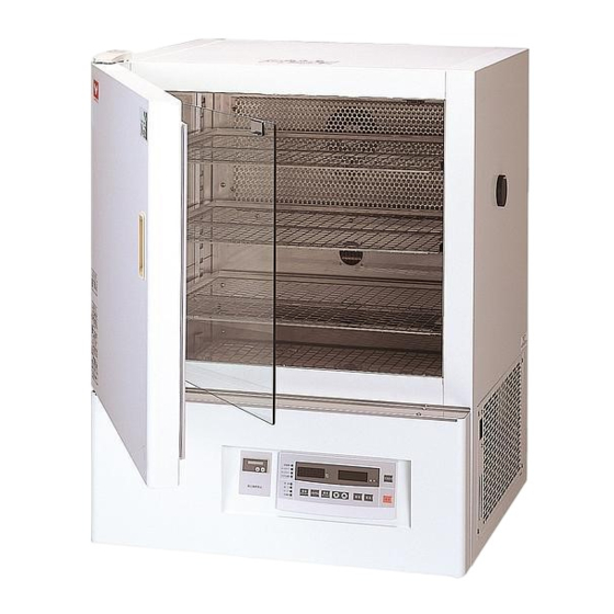
Programmable
Low Temperature Incubator
Model
IN604/804
Instruction Manual
- First Edition -
Thank you for purchasing " Programmable Low
Temperature Incubator, IN Series" of Yamato
Scientific Co., Ltd.
To use this unit properly, read this "Instruction
Manual" thoroughly before using this unit.
Keep this instruction manual around this unit for
referring at anytime.
WARNING!:
Carefully read and thoroughly understand the
important warning items described in this
manual before using this unit.
Yamato Scientific America Inc.
This paper has been printed on recycled paper.
Advertisement
Table of Contents


Need help?
Do you have a question about the IN604 and is the answer not in the manual?
Questions and answers