
Related Manuals for EBS CPX220NWB


Summary of Contents for EBS CPX220NWB
- Page 1 ALARM CONTROL UNIT CPX220NWB Installation and programming manual Version of the manual: v1.2 Date of issue: 2016.10.27 Firmware version: 2.6.3 GPRS transmitter configurator version: 1.3.64.3 OSM server version: 1.3.60.4...
- Page 2 DECLARATION OF COMPLIANCE We, EBS Sp. z o.o., declare with full responsibility that the present product meets all requirements provided for in the Directive 1999/5/EC of European Parliament and Council dated 9 March 1999. The copy of the “Declaration of Compliance”...
-
Page 3: Table Of Contents
EMERGENCY BUTTONS ......................41 4.4. TEXT MESSAGES CONFIGURATION ....................42 CONFIGURATION WIZARD ......................51 5.1. PRELIMINARY NOTES ........................51 5.2. COMPUTER – REQUIREMENTS ......................51 5.3. PROGRAM FUNCTONS ........................51 CPX220NWB ALARM CONTROL UNIT – INSTALLER MANUAL 3 / 123... - Page 4 SMS FORWARD ........................93 6.9. LINK CONTROL ..........................94 6.9.1. GSM ............................94 6.9.2. GPRS ............................. 95 6.10. FIRMWARE ............................. 95 6.11. DEVICE MONITORING ........................96 6.12. EVENTS HISTORY ........................... 97 CPX220NWB ALARM CONTROL UNIT – INSTALLER MANUAL 4 / 123...
- Page 5 DRAWING 9. CONTROL PANEL HORIZONTAL LOCATION .................. 26 DRAWING 10. CONTROL PANEL VERTICAL LOCATION ..................26 DRAWING 11. SIGNAL LOSS THROUGH CONSTRUCTION MATERIALS..............27 DRAWING 12. SENSOR PLACEMENT ........................ 28 CPX220NWB ALARM CONTROL UNIT – INSTALLER MANUAL 5 / 123...
-
Page 6: Introduction
1. INTRODUCTION Thank you for choosing EBS alarm control unit. CPX220NWB is a simple, functional alarm control unit integrated with GSM/GPRS/SMS transmitter, intended for small- and medium- sized facilities. The central unit is equipped with 3 outputs and 16 zones with the possibility to be divided into 2 partitions. Dedicated KP16 LED keypad was designed in a modern, discreet style. -
Page 7: Control Unit Functions
Possibility to restrict the scope of authorization to a few codes only SYSTEM OPTIONS Automatic diagnosis of basic system components Possibility to review faults, alarm memories, event log System/technical event history – min. 5000 events CPX220NWB ALARM CONTROL UNIT – INSTALLER MANUAL 7 / 123... -
Page 8: Specifications
Lead-acid 12V Low voltage – event treshold: Voltage battery cut off level: below 9V Working temperature: -10ºC to +55ºC Working humidity: 5% to 93% PCB dimensions: 152 x 78 x 30mm CPX220NWB ALARM CONTROL UNIT – INSTALLER MANUAL 8 / 123... -
Page 9: Accessories And Software Applications
Communication Server for Alarm Receiving Center Mobile Configuration App of GPRS Transmitters. AVA INSTALL For Installers (Android) Mobile Monitoring application for controll and monitoring of controll panel. (Android, iOS). For Users. CPX220NWB ALARM CONTROL UNIT – INSTALLER MANUAL 9 / 123... -
Page 10: Installation And Wiring
NOTE: If you use more than one keyboard in the system, be sure to address each assignment of the keyboard (see chapter 3.6.4.). 9. Verify the operation of the system and all its components. CPX220NWB ALARM CONTROL UNIT – INSTALLER MANUAL 10 / 123... -
Page 11: Description Of Pcb Elements
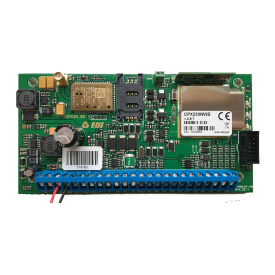
(especcialy wires). Don’t put antennas into cases (above all in metal cases). Antenna wire shouldn’t be flexed or rucked. There is not recommend to extend antenna wire. CPX220NWB ALARM CONTROL UNIT – INSTALLER MANUAL 11 / 123... - Page 12 9. Screw terminals of the control unit For detailed information on feeding, input and output connectors, please refer to chapter 3.3. Assembly holes of the control unit (132x61mm hole span) CPX220NWB ALARM CONTROL UNIT – INSTALLER MANUAL 12 / 123...
- Page 13 OBDNA casing can be ordered (the casing includes appropriate 230VAC/18VAC transformer). Wireless module antenna connector CPX220NWB included two types of antennas: internal and external dipole type. 433MHz internal antenna Internal antenna can be used wherever required compact size and antenna provides appropriate coverage level detectors.
- Page 14 GND socket. Correct install position for dipol antenna in the attached photo below. Wireless module The wireless module is used to receive signals from remote controls and wireless detectors. CPX220NWB ALARM CONTROL UNIT – INSTALLER MANUAL 14 / 123...
-
Page 15: Description Of Screw Terminals Of The Control Unit
3.3. DESCRIPTION OF SCREW TERMINALS OF THE CONTROL UNIT NOTE: Any assembly and installation works shall be carried out with power supply off and battery disconnected. Drawing 2. Description of screw terminals of the control unit CPX220NWB ALARM CONTROL UNIT – INSTALLER MANUAL 15 / 123... -
Page 16: Configuration Of Wired Input Lines
(DEOL-NO or DEOL-NC) using 1.1kΩ resistors. Both resistor types are included in the delivery of the control unit. Various configurations of input lines are presented in the drawing 3. Drawing 3. Configuration of input lines CPX220NWB ALARM CONTROL UNIT – INSTALLER MANUAL 16 / 123... -
Page 17: Sample Connection Of Signalling Device
3.5. SAMPLE CONNECTION OF SIGNALLING DEVICE 3.5.1. Internal signalling device without independent source of power supply Drawing 4. Sample connection of internal signalling device without independent source of power supply CPX220NWB ALARM CONTROL UNIT – INSTALLER MANUAL 17 / 123... -
Page 18: External Signalling Device With Independent Source Of Power Supply
3.5.2. External signalling device with independent source of power supply Drawing 5. Sample connection of external signalling device with independent source of power supply CPX220NWB ALARM CONTROL UNIT – INSTALLER MANUAL 18 / 123... -
Page 19: Kp16 Keypad
2. ALARM LED (red): Flashing light – means that alarms were present in the system (alarm memory). Constant light – means that system is in alarm state. Off – system is operating correctly. CPX220NWB ALARM CONTROL UNIT – INSTALLER MANUAL 19 / 123... - Page 20 After the keypad is assembled the switch contact is closed. Unauthorized disassembly of the keypad will send the message to the alarm control unit 12. - 14. Emergency buttons See item 4.3.11. Emergency buttons and 6.3.6. Emergency Buttons. CPX220NWB ALARM CONTROL UNIT – INSTALLER MANUAL 20 / 123...
-
Page 21: Keypad Specification
, which means a new keypad address. 3. After about 5 seconds the keypad will display the programmed keypad address. 4. After programming the keypad address, reset the control panel CPX220NWB. CPX220NWB ALARM CONTROL UNIT – INSTALLER MANUAL 21 / 123... -
Page 22: Wireless Keypad Kp1W
3.7. WIRELESS KEYPAD KP1W The wireless keypad KP1W was designed to work with the hybrid central panel CPX220NWB. There is a possibility to add three of these keypads, however each of them occupies one of 16 input lines. The transmission between the keypad and the central panel is protected with changing code and encrypted. -
Page 23: Description Of Keypad Elements
4. and 10. Anti-sabotage switch After the keypad is assembled the switch contact is closed. Unauthorized disassembly of the keypad will send the message to the alarm control unit. 5. Canal for wires CPX220NWB ALARM CONTROL UNIT – INSTALLER MANUAL 23 / 123... -
Page 24: Keypad Specification
125 x 102 x 33 mm Wight without battery 150 g *Working conditions: test transmission every 15 minutes, keyboard use (arming/disarming) 2 times a day, open door switch closed, working temperature 20°C CPX220NWB ALARM CONTROL UNIT – INSTALLER MANUAL 24 / 123... -
Page 25: Keypad Installation
The connector can be found on the keypad board and labelled 9 in Figure 7. This sensor in the alarm system CPX220NWB will have assigned the same line number as the keypad. 3.8. CONTROL PANEL LOCATION The control panel should be located in the central part of the object. -
Page 26: Drawing 9. Control Panel Horizontal Location
Medium attenuation have light concrete and brick walls. Reinforced concrete and metal latticed plaster have the greatest attenuation. The drawing 11 shows the signal loss through various different types of materials. CPX220NWB ALARM CONTROL UNIT – INSTALLER MANUAL 26 / 123... -
Page 27: Drawing 11. Signal Loss Through Construction Materials
Drawing 11. Signal loss through construction materials CPX220NWB ALARM CONTROL UNIT – INSTALLER MANUAL 27 / 123... -
Page 28: Wireless Detectors Installation Recommendations
In this way you get the best radio coverage. Additional installation tips describes the drawing 12. Drawing 12. Sensor placement CPX220NWB ALARM CONTROL UNIT – INSTALLER MANUAL 28 / 123... -
Page 29: Service Mode
After pressing the numerical button, the lately entered digit is displayed on a keypad. The way the digits are displayed on a keypad is presented in the table below: CPX220NWB ALARM CONTROL UNIT – INSTALLER MANUAL 29 / 123... -
Page 30: Activation Of Service Mode
Power loss time raport Reset to default settings System options Users remote manager Zones configuration <XX> <Y> Outputs configuration <XX> <Y> Partitions configuration <XX> <Y> Wireless zones configuration <XX> <Y> CPX220NWB ALARM CONTROL UNIT – INSTALLER MANUAL 30 / 123... -
Page 31: Installer Code
BIT type. By pressing 1, 2, 3, 4, 5 and 6 keys, you can switch on/off proper option. 3 beeps will confirm the successfully entered function. <Options> Where: Options – number of option (BIT type parameter): CPX220NWB ALARM CONTROL UNIT – INSTALLER MANUAL 31 / 123... -
Page 32: Users Remote Management
That function allow to switch on or switch off remote users management. The argument of the function is BIT type. By pressing key 1, you can switch on/off option. 3 beeps will confirm the successfully entered function. <Options> CPX220NWB ALARM CONTROL UNIT – INSTALLER MANUAL 32 / 123... -
Page 33: Zones Configuration
4 – number of alarms after which the zone will be automatically blocked until re- arming (DEC type parameter). If 0, zone will not be blocked. 5 – zone options (BIT type parameter): CPX220NWB ALARM CONTROL UNIT – INSTALLER MANUAL 33 / 123... -
Page 34: Outputs Configuration
Codes of output configuration functions are defined as per the following pattern: <XX> <Y> where: CPX220NWB ALARM CONTROL UNIT – INSTALLER MANUAL 34 / 123... - Page 35 3 output type into triggered by power failure: c) change of many parameters at the time for output 1 using complex function – output 1 is to be set as alarm signalling with activation time 120 seconds: CPX220NWB ALARM CONTROL UNIT – INSTALLER MANUAL 35 / 123...
-
Page 36: Partitions Configuration
8 – auto-disarming time (DEC type parameter, time of day written in the 24-hour notation in the form HHMM), 9 – auto-disarming option (BIT type parameter): o 1 – auto-disarming activation/deactivation Notes: CPX220NWB ALARM CONTROL UNIT – INSTALLER MANUAL 36 / 123... - Page 37 Press cancel changes entered in currently configured parameter only and exit service function – previously entered parameters, confirmed with , will not be cancelled. CPX220NWB ALARM CONTROL UNIT – INSTALLER MANUAL 37 / 123...
-
Page 38: Wireless Zones Configuration
Example: a) delete a wireless sensor no. 10: b) add a wireless sensor no. 11: CPX220NWB ALARM CONTROL UNIT – INSTALLER MANUAL 38 / 123... -
Page 39: Remote Controllers Configuration
Codes of the remote control configuration functions are defined as per the following pattern: <XX> <Y> Where: XX – determines the number of remote control CPX220NWB ALARM CONTROL UNIT – INSTALLER MANUAL 39 / 123... - Page 40 1: b) add a remote control no. 1: 4.3.10.2. Delete all remote controllers To remove all remote controllers from the system, enter the following function: CPX220NWB ALARM CONTROL UNIT – INSTALLER MANUAL 40 / 123...
-
Page 41: Emergency Buttons
Functions which configure all three buttons, will not change the outputs setting. Example: a) enabling all emergency buttons: b) enabling “panic” (burglary) function ( held) and changing output 2 and output 3 state: CPX220NWB ALARM CONTROL UNIT – INSTALLER MANUAL 41 / 123... -
Page 42: Text Messages Configuration
CPX220NWB can store up to 10 phone numbers and up to 32 text messages. If, for any reason, the SMS can not be send at the moment, it will be send as soon as the connection with the GSM network is re-established but not later than 1 day after the occurrence of the event triggering SMS send request (text messages get expired and are deleted). - Page 43 VALUE – new name of the partition Example 1: 1234 SETNAME=PARTITION,1,Cellar Example 2: 1234 SETNAME="PARTITION,2,Kids Room" Feedback message SETNAME::OK or SETNAME:ERROR Feedback message SETNAME::OK – command accepted description SETNAME:ERROR – command rejected by the system CPX220NWB ALARM CONTROL UNIT – INSTALLER MANUAL 43 / 123...
- Page 44 NUMBER – phone number, on which the texts will be send Example: 1234 SETTELNUM=3,800123456 Feedback message SETTELNUM:OK SETTELNUM:ERROR Feedback message SETTELNUM:OK – command accepted description SETTELNUM:ERROR – command rejected by the system CPX220NWB ALARM CONTROL UNIT – INSTALLER MANUAL 44 / 123...
- Page 45 ID – index of text, possible values: 1 to 32 MESSAGE – content of the text message Example: 1234 SETMESSAGE=4,Robbery Feedback message SETMESSAGE:OK or SETMESSAGE:ERROR Feedback message SETMESSAGE:OK – command accepted description SETMESSAGE:ERROR – command rejected by the system CPX220NWB ALARM CONTROL UNIT – INSTALLER MANUAL 45 / 123...
- Page 46 ID – index of text, possible values: 1 to 32 Example: 1234 GETMESSAGE=30 Feedback message GETMESSAGE=ID,MESSAGE GETMESSAGE:ERROR Feedback message GETMESSAGE=ID,MESSAGE – information about the description contents of text message GETMESSAGE:ERROR – command rejected by the system CPX220NWB ALARM CONTROL UNIT – INSTALLER MANUAL 46 / 123...
- Page 47 6 will be sent to phone numbers with indexes 1,8 and 9. Feedback message SETUSERSMS=EVENT,TELNUM,MSG_ID:OK SETUSERSMS=EVENT,TELNUM,MSG_ID:ERROR Feedback message SETUSERSMS=EVENT,TELNUM,MSG_ID:OK – description command accepted SETUSERSMS=EVENT,TELNUM,MSG_ID:ERROR – command rejected by the system CPX220NWB ALARM CONTROL UNIT – INSTALLER MANUAL 47 / 123...
- Page 48 Example: 1234 GETUSERSMS=ARM1 Feedback message GETUSERSMS=EVENT:TELNUM,MSG_ID GETUSERSMS=EVENT:ERROR Feedback message GETUSERSMS=EVENT:TELNUM,MSG_ID – description information about text message and phone number assinged to the event GETUSERSMS=EVENT:ERROR – command rejected by the system CPX220NWB ALARM CONTROL UNIT – INSTALLER MANUAL 48 / 123...
- Page 49 (to OUTPUT3-TAMPER) OUTPUT1-TAMPEREND Fault of zones 1…3 ended (to OUTPUT3-TAMPEREND) POWER-FAIL Power failure POWER-OK Power failure ended BATTERY-FAIL Battery failure BATTERY-OK Battery failure ended AUX1-FAIL Failure of auxiliary output 1 CPX220NWB ALARM CONTROL UNIT – INSTALLER MANUAL 49 / 123...
- Page 50 List of errors sent as feedback messages Alias name Description ERROR-PERMISSION Permission to issue this command was not granted ERROR-FORMAT Wrong command syntax ERROR-VALUE Wrong parameter value ERROR-EMPTY Parameter value missing ERROR Other error CPX220NWB ALARM CONTROL UNIT – INSTALLER MANUAL 50 / 123...
-
Page 51: Configuration Wizard
5.1. PRELIMINARY NOTES The configuration wizard of GPRS transmitters can be downloaded from www.ebs.pl (login: ebs, password: ebs). Activate the option of installation wizard which leads through the program installation process. By default it will be installed in C:\Program Files\EBS\ directory. -
Page 52: Menu -> File
Opens a new set of parameters. In this option configuration parameters of the equipment can be edited. Select a relevant type of the equipment: CPX220NWB 5.3.1.2. File -> Open If you have a file with recorded settings you can use it for programming another equipment. - Page 53 Click [Add] button to confirm the setting. The connection is saved (and moved to the table). From that moment the program will enable a wire connection with the equipment and allows reading and recording the parameters in the equipment’s memory. CPX220NWB ALARM CONTROL UNIT – INSTALLER MANUAL 53 / 123...
- Page 54 Connection function (or clicking icon on a taskbar) and opening GSM Modem tab. The window will be displayed on the screen where you define: Connection name, e.g. RemoteCSD CPX220NWB ALARM CONTROL UNIT – INSTALLER MANUAL 54 / 123...
- Page 55 C:\Program Files\EBS\KonfiguratorLX\configs\CPX220NWB_20000\ CPX220NWB_20000 directory contains all files related to programming the CPX220NWB type device of the serial number 20000. Files names contain date and time of the operation and its type (recording/reading). The files are recorded with .cmi extension.
-
Page 56: Menu -> Operations
It is also possible to set internal timer of the device. For the above you have to check the box “Set the time” and enter a respective date and time. A correct entry is confirmed with a relevant message. CPX220NWB ALARM CONTROL UNIT – INSTALLER MANUAL 56 / 123... - Page 57 The function enables to read out the events lately recorded in the memory of the equipment. Please refer to chapter 6.12. 5.3.2.5. Operations -> Equipment monitoring The function allows the on-going monitoring of the equipment condition. Please refer to chapter 6.11. CPX220NWB ALARM CONTROL UNIT – INSTALLER MANUAL 57 / 123...
-
Page 58: Menu -> Help
(and sends) information only from equipment that is registered in its database, the first operation you have to do for remote programming it to properly register the equipment. The procedure is described in OSM.2007 user manual. CPX220NWB ALARM CONTROL UNIT – INSTALLER MANUAL 58 / 123... - Page 59 Close the configuration wizard’s window after you finish the data input. The equipment is ready for data transmission in accordance with new settings. CPX220NWB ALARM CONTROL UNIT – INSTALLER MANUAL 59 / 123...
-
Page 60: Programmable Parameters
GPRS: GPRS transmission (TCP/IP protocol) in standard. In case of any problems with that connection, no remote connection is possible No server connection: no transmission with server, remote communication with a user is possible only via SMS messages CPX220NWB ALARM CONTROL UNIT – INSTALLER MANUAL 60 / 123... -
Page 61: Access Point Name
It defines the name of access point to GPRS network. There is a possibility to obtain a private access point. In this case its name will be given by a particular GSM network operator. CPX220NWB ALARM CONTROL UNIT – INSTALLER MANUAL 61 / 123... -
Page 62: Primary Server Parameters
After a defined number of attempts, the equipment will initiate the procedure of connecting with secondary server. The option is active only in case the secondary server parameters were defined. CPX220NWB ALARM CONTROL UNIT – INSTALLER MANUAL 62 / 123... -
Page 63: Secondary Server Parameters
(in TCP/IP or SMS mode). Default factory setting is 0000. It should be changed at first equipment start-up (programming). The code can be composed of from four to seven digits. CPX220NWB ALARM CONTROL UNIT – INSTALLER MANUAL 63 / 123... - Page 64 PUK code (using any GSM phone). Default factory PIN code entered in the equipment is: 1111. CPX220NWB ALARM CONTROL UNIT – INSTALLER MANUAL 64 / 123...
-
Page 65: Transmission
GPRS and SMS transmissions. In case encrypted transmission was selected, you can enter own data encryption key (DEK) (256 bits - 0-9 and A-F characters) or use default setting. CPX220NWB ALARM CONTROL UNIT – INSTALLER MANUAL 65 / 123... -
Page 66: Inputs / Outputs
Instant – disruption of the line causes immediate alarm, if the system is armed. Delay – that type of line is usually used for detectors operation at the facility entries. The line switches into alarm state after the expiration of programmed CPX220NWB ALARM CONTROL UNIT – INSTALLER MANUAL 66 / 123... - Page 67 If this is not violated during exit time countdown, partition will be armed in the stay mode. If the system is armed, this zone behaves like the delayed zone. CPX220NWB ALARM CONTROL UNIT – INSTALLER MANUAL 67 / 123...
- Page 68 6.3.1.4. Sensitivity That parameter defines a minimum time the change must maintain at the particular zone, to be detected by a transmitter. Default factory setting of the parameter is 400 ms. CPX220NWB ALARM CONTROL UNIT – INSTALLER MANUAL 68 / 123...
- Page 69 First alarm will be generated after the line is returned and violated again. . 6.3.1.7. Ignore during arming Zone can be violated during partition arming (e.g. delay circuits shall be set to that option). CPX220NWB ALARM CONTROL UNIT – INSTALLER MANUAL 69 / 123...
-
Page 70: Wireless Zones
6.3.2. Wireless zones CPX220NWB is capable of storing information about up to 16 wirelles inputs number from 1 to 16. Remove the front cover of the detector that you want to enroll to the control panel. It is recommended to add wireless sensors individually. To prevent the accidental transmissions from other detectors, only one detector cover should be removed during the procedure of adding a new detector. - Page 71 A new window appears. Configurator will be waiting for a wirells signal to come. User has to press for a while the tamper switch on the sensor. CPX220NWB will detect the transmission and print sensor’s type and ID. Add Device To bind this sensor with the Alarm Control Unit, press .
- Page 72 Sensor preferences can be set now in the Inputs tab. You can choose the same options as for wired zones excluding sensitivity. CPX220NWB ALARM CONTROL UNIT – INSTALLER MANUAL 72 / 123...
-
Page 73: Partitions
6.3.3.4. Alarm time The parameter defines the time the alarm will be indicated by KP16 keypad. 6.3.3.5. Partition name The parameter allows you to give any name for the partition. CPX220NWB ALARM CONTROL UNIT – INSTALLER MANUAL 73 / 123... - Page 74 NOTE: To use the auto-arming/disarming function, you should do a firmware upgrade to version 2.4.7 or higher, then read and write the configuration of the device using “GPRS transmitters configurator” program in version 1.3.57.3 or higher. CPX220NWB ALARM CONTROL UNIT – INSTALLER MANUAL 74 / 123...
-
Page 75: Outputs
40ms. In the case of set time for exit chirp is generated after arming, similarly in the case of the time for entry chirp is generated after disarming. Alarm & chirp – The output is activated when alarm is detected or when arming/disarming. CPX220NWB ALARM CONTROL UNIT – INSTALLER MANUAL 75 / 123... -
Page 76: Remote Controllers
Pressing OK will invoke new window indicating, that CPX220NWB is waiting for incoming tranmisson from the remote controller. User has to press one of the controller button, in order to bind it with the Alarm Control Unit. Device’s CPX220NWB ALARM CONTROL UNIT –... - Page 77 For normal and silent alarm can be sent a message to the monitoring station, depending on the configuration of the control panel. The control panel allows you to assign remote control buttons to various functions. It is possibile to configure different alarm button. CPX220NWB ALARM CONTROL UNIT – INSTALLER MANUAL 77 / 123...
-
Page 78: Emergency Buttons
User can choose which outputs should be turned on in case of the emergency button activation (pressing and holding a button for 3 seconds). Each of the outpus has the reminder of it’s function chosen in the “Outputs” tab. CPX220NWB ALARM CONTROL UNIT – INSTALLER MANUAL 78 / 123... -
Page 79: System Options
Checking alarm memory and fault memory will be available only after entering user code. This option must be enabled in order to comply with EN 50131 standard requirements for Grade 2. CPX220NWB ALARM CONTROL UNIT – INSTALLER MANUAL 79 / 123... -
Page 80: Alarms And Inputs Interlocking States Are Not Displayed
This option allows user managing. To be able to manager the users one has to press the ‘Edit’ button first and the input the correct administrator code. Granted the authorization, it will be possible to edit the users’ passwords and partition priviliages. CPX220NWB ALARM CONTROL UNIT – INSTALLER MANUAL 80 / 123... -
Page 81: Monitoring
That option allows determining which of available signals generated by the equipment will be transmitted to the monitoring station. NOTE: The “Configuration change” event refers to configuration change via SMS or via GPRS instructions only. CPX220NWB ALARM CONTROL UNIT – INSTALLER MANUAL 81 / 123... -
Page 82: Events
(normalisation). In order to transmit a particular signal you have to check it (by clicking a relevant check box on the right hand side). Press [Clear] button to remove all checked signals. Press [Reverse] to reverse the check into the opposite ones. CPX220NWB ALARM CONTROL UNIT – INSTALLER MANUAL 82 / 123... -
Page 83: Additional Data
GSM status – status about connection to GSM network, type of connection to server (GPRS/SMS), information about ongoing phone calls GSM signal level quality – quality of connection to GSM network (CSQ and BER parameters) CPX220NWB ALARM CONTROL UNIT – INSTALLER MANUAL 83 / 123... -
Page 84: Restrictions
To remove the number from the table, place the cursor in a particular number line and click [Remove]. “Remove all” option will clear all the numbers from the table. CPX220NWB ALARM CONTROL UNIT – INSTALLER MANUAL 84 / 123... - Page 85 SMS tests to server SMS events sent to server SMS events sent to the user Replies to commands CPX220NWB ALARM CONTROL UNIT – INSTALLER MANUAL 85 / 123...
- Page 86 SMS, e.g. in case of a fault. Counter reset: That parameter defines time (in minutes) after which the counter of SMS sent is to be reset. CPX220NWB ALARM CONTROL UNIT – INSTALLER MANUAL 86 / 123...
-
Page 87: Remote Commands
6.7.2. Remote commands 6.7.2.1. Users remote management enable Selecting this option allows you to remotely configure user accounts. -
Page 88: Sms Notifications
6.8. SMS NOTIFICATIONS 6.8.1. Phones CPX220NWB can notify users about occurrence of certain events by text message. Before sending the message, may occur an additional attempt a voice call (see item 6.8.4. Options). In order to add user’s number to the notification list, one has to type in the number next to the number index. -
Page 89: Messages
In text messages can be used only alphanumeric characters, as well as: ! @ # $ % " < > & * ( ) + : ? ` ; ' = , . / and space. CPX220NWB ALARM CONTROL UNIT – INSTALLER MANUAL 89 / 123... -
Page 90: Events
From now on, whenever this event occurs, a text containing selected message will be send to the selected phone numbers. Before sending the message, may occur an additional attempt a voice call (see item 6.8.4. Options). CPX220NWB ALARM CONTROL UNIT – INSTALLER MANUAL 90 / 123... -
Page 91: Options
Note: The producer does not recommend using this option because it reduces security of the system. The option for use only by advanced users. CPX220NWB ALARM CONTROL UNIT – INSTALLER MANUAL 91 / 123... - Page 92 CPX220NWB ALARM CONTROL UNIT – INSTALLER MANUAL 92 / 123...
-
Page 93: Sms Forward
NOTE: The user is responsible for correct entering the telephone numbers that prevents any turmoil in sending SMS messages. CPX220NWB ALARM CONTROL UNIT – INSTALLER MANUAL 93 / 123... -
Page 94: Link Control
Device reset In case the equipment lost the GSM connection, it shall wait for a defined period of time after the fact was ascertained and then it shall perform stipulated tasks. CPX220NWB ALARM CONTROL UNIT – INSTALLER MANUAL 94 / 123... -
Page 95: Gprs
The equipment has integrated bootloader that enables module software update. During the programming all that process information is displayed. The following activities shall be performed: Start configuration wizard, Go to wizard’s “Firmware” option, CPX220NWB ALARM CONTROL UNIT – INSTALLER MANUAL 95 / 123... -
Page 96: Device Monitoring
GD-PROG cable in DEBUG mode and then, in “Port” box select an appropriate RS232 port. Monitor allows the control of the following parameters: Condition of mains power supply GSM network signal strength and bit error ratio (BER) CPX220NWB ALARM CONTROL UNIT – INSTALLER MANUAL 96 / 123... -
Page 97: Events History
“Read” button. After correct reading you will get the access to “Filtering” and “Graphs” functions which allow you a quick diagnosis of the equipment. CPX220NWB ALARM CONTROL UNIT – INSTALLER MANUAL 97 / 123... - Page 98 CPX220NWB ALARM CONTROL UNIT – INSTALLER MANUAL 98 / 123...
-
Page 99: Led Indication
GSM range = 8 GPRS mode GSM range = 6 SMS mode 7.3. TRANSMISSION During data transmission green LED indicates the data sending. LEDs Description ERROR STATUS (green) (red) (yellow) GPRS transmission transmission CPX220NWB ALARM CONTROL UNIT – INSTALLER MANUAL 99 / 123... -
Page 100: Programming
During the equipment’s operation errors can occur. Error is indicated by constant light of red LED and most often it means a communication problem with a modem or SIM card. CPX220NWB ALARM CONTROL UNIT – INSTALLER MANUAL 100 / 123... -
Page 101: Grade 2 Settings
- Input 1 – 16 tamper - Output 1 – 3 tamper - Power - Battery - Jamming - Keypad output failure - Output AUX1 failure - Output AUX2 failure CPX220NWB ALARM CONTROL UNIT – INSTALLER MANUAL 101 / 123... -
Page 102: The Behavior Of The System In Compatibility Mode For Grade 2
the codes in the system must be at least 5 characters after entering an invalid code three times, all keypads in the system will be blocked for 90 seconds. CPX220NWB ALARM CONTROL UNIT – INSTALLER MANUAL 102 / 123... -
Page 103: Extras
However, there are parameters, changes to which will be detected only in special circumstances, for example – the server address. If it is changed when the device is online, a restart is needed. When CPX220NWB boots up, it will connect to the newly configured address. -
Page 104: Configuration Parameters
Sets the phone number for sending SMS with the events in the absence of GPRS communication. If the number is not configured sending SMS messages will not be available. Phone_number may contain a prefix of the country. CPX220NWB ALARM CONTROL UNIT – INSTALLER MANUAL 104 / 123... -
Page 105: General Commands
, and it will not necessarily be the first command in the list. 9.1.2.1. DISC Format: DISC Limitations: Can be executed by ATS only Description Disconnects TCP connection with OSM server CPX220NWB ALARM CONTROL UNIT – INSTALLER MANUAL 105 / 123... - Page 106 PORT – OSM server port APN – APN name by means of which the GPRS session is compiled UN – APN user name PW –APN password DNS0 –DNS server address CPX220NWB ALARM CONTROL UNIT – INSTALLER MANUAL 106 / 123...
- Page 107 Format: GETSTATUS Limitations: Can be executed by ATS, administrator or user. Description Gets the current status of the device. The returned data are in the following format: zones,partitions,outputs,battery_voltage,voltage_AC,0x0,0x0, blocked_zones where: CPX220NWB ALARM CONTROL UNIT – INSTALLER MANUAL 107 / 123...
-
Page 108: Commands For Managing The Users In Cp
Battery_voltage – battery voltage in mV (12000 = 12V). If the battery is not connected, the readings may be incorrect, and be around 9V (9000) voltage_AC – AC voltage at the AC terminals of CPX220NWB (downstream the transformer) in mV (18000 = 18V) blocked_zones –... - Page 109 If the specified password is incorrect CPGETUSERID:ENOT_ALLOWED If the command is sent via open SMS or the configuration does not allow remote management of users CPGETUSERID:EFORMAT If the format of the sent command is incorrect CPX220NWB ALARM CONTROL UNIT – INSTALLER MANUAL 109 / 123...
- Page 110 If the administrator password specified is incorrect CPSETUSERPARTITIONS:ENOT_ALLOWED If the command is sent via open SMS or the configuration does not allow remote management of users CPSETUSERPARTITIONS:EFORMAT If the format of the sent command is incorrect CPX220NWB ALARM CONTROL UNIT – INSTALLER MANUAL 110 / 123...
- Page 111 If the new password is too short or too long or does not consist of digits CPSETUSERPASSWORD:ENOT_ALLOWED If the command is sent via open SMS or the configuration does not allow remote management of users CPSETUSERPASSWORD:EFORMAT If the format of the sent command is incorrect CPX220NWB ALARM CONTROL UNIT – INSTALLER MANUAL 111 / 123...
- Page 112 8 inclusive. The command needs the option“Allow remote user management” to be set active in the Configurator. Can be executed only by ATS or administrator. If the command is executed by ATS, specify adminPassword CPX220NWB ALARM CONTROL UNIT – INSTALLER MANUAL 112 / 123...
- Page 113 If the new password is too short or too long or does not consist of digits CPSETADMINPASSWORD: EPERMISIONS If the password can not be changed because it is already used by another user. If you type the current administrator password, the command returns EOK. CPX220NWB ALARM CONTROL UNIT – INSTALLER MANUAL 113 / 123...
-
Page 114: Commands For Managing The Partitions, Zones And Outputs
– battery voltage in mV (12000 = 12V). If the battery is not connected, the readings may be incorrect, and be around 9V (9000) powerSupplyVoltage – AC voltage at AC terminals of CPX220NWB (downstream the transformer) in mV (18000 = 18V). - Page 115 This parameter values are valid only for armed partitions. CPGETSTATUS:EPERMISIONS If the specified password is incorrect CPGETSTATUS:ENOT_ALLOWED If the command was sent via open SMS CPDELUSER:EFORMAT If the format of the sent command is incorrect CPX220NWB ALARM CONTROL UNIT – INSTALLER MANUAL 115 / 123...
- Page 116 1 – configuration memory failure CPGETFAILURES:EPERMISIONS If the specified password is incorrect CPGETFAILURES:ENOT_ALLOWED If the command was sent via open SMS CPDELUSER:EFORMAT If the format of the sent command is incorrect CPX220NWB ALARM CONTROL UNIT – INSTALLER MANUAL 116 / 123...
- Page 117 CPSETPARTITIONS=[STAY,]partitions,password:EFORMAT If the data format is incorrect (partitions,password are the command arguments) CPSETPARTITIONS=[STAY,]partitions:EPERMISIONS If the user with the specified password does not exist CPX220NWB ALARM CONTROL UNIT – INSTALLER MANUAL 117 / 123...
- Page 118 CPUNSETPARTITIONS=partitions,password:EFORMAT If the data format is incorrect (partitions,password are the command arguments) CPUNSETPARTITIONS=partitions:EPERMISIONS If the user with the specified password does not exist CPX220NWB ALARM CONTROL UNIT – INSTALLER MANUAL 118 / 123...
- Page 119 If the format of the sent command is incorrect CPZONESLOCK:EPERMISIONS If the user has not authorization to the proper partition CPZONESLOCK:ENOT_EXISTS If the user with the specified password does not exist CPX220NWB ALARM CONTROL UNIT – INSTALLER MANUAL 119 / 123...
- Page 120 If the format of the sent command is incorrect CPZONESUNLOCK:EPERMISIONS If the user has not authorization to the proper partition CPZONESUNLOCK:ENOT_EXISTS If the user with the specified password does not exist CPX220NWB ALARM CONTROL UNIT – INSTALLER MANUAL 120 / 123...
- Page 121 0) means the zone 1. CPPARTITIONSGETZONES:EPERMISIONS If the specified password is incorrect CPPARTITIONSGETZONES:ENOT_ALLOWED If the command was sent via open SMS CPPARTITIONSGETZONES:EFORMAT If the format of the sent command is incorrect CPX220NWB ALARM CONTROL UNIT – INSTALLER MANUAL 121 / 123...
- Page 122 0) means the output 1. CPPARTITIONSGETOUTPUTS:EPERMISIONS If the specified password is incorrect CPPARTITIONSGETOUTPUTS:ENOT_ALLOWED If the command was sent via open SMS CPPARTITIONSGETOUTPUTS:EFORMAT If the format of the sent command is incorrect CPX220NWB ALARM CONTROL UNIT – INSTALLER MANUAL 122 / 123...
-
Page 123: Change History
Added information about smoke detector SD-20 and wireless 2016.10.21 / i1.1 / 2.6.2 keypad KP1W Added information about flood detector FL-10 and wireless 2016.10.27 / i1.2 / 2.6.3 magnetic contact MC-11 CPX220NWB ALARM CONTROL UNIT – INSTALLER MANUAL 123 / 123...
Need help?
Do you have a question about the CPX220NWB and is the answer not in the manual?
Questions and answers