Table of Contents
Advertisement
Advertisement
Table of Contents

Related Manuals for Unipulse F701-C


Summary of Contents for Unipulse F701-C
- Page 1 F701-C WEIGHING CONTROLLER OPERATION MANUAL 01 Apr. 2015 Rev. 1.16...
-
Page 2: Safety Precautions
Thank you very much for purchasing our Weighing Controller F701-C. For good performance, and proper and safe use of the F701-C, be sure to read this instruction manual and properly understand the contents of it before use. Also, carefully keep this instruction manual so that it can be referred to at any time. - Page 3 - Use greatly impacting human lives and assets, such as medical devices, transport devices entertainment devices, and safety devices. Warning on installation ● Do not disassemble, repair, or modify the F701-C. Doing so may cause a fire or an electric shock. ● Do not install in the following environments.
- Page 4 - Where static electricity, relay noise or the like is generated. ● Install the F701-C as far away from devices generating high frequency, high voltage, large current, surge, etc., as possible. Also, carry out wiring separately from their power lines. Do not carry out parallel wiring and common wiring.
- Page 5 ● For turning on/off the power, be sure to keep intervals of 5 seconds or more. ● After power-on, make sure to warm up the F701-C for at least 30 minutes or more before use. ● If the F701-C is not used by the specified method, its protective performance may be impaired.
-
Page 6: Table Of Contents
CONTENTS CONTENTS 1.APPEARANCE DESCRIPTION ..........1 1-1.Front Panel ....................1 1-2.Rear Panel ..................... 6 2.CONNECTION ................8 2-1.Load cell Connection ................... 8 2-1-1.6-wire Connection ..................10 2-1-2.4-wire Connection ..................10 2-1-3.Connecting Load cells in Parallel ............... 11 2-1-4.Sensor Cable ....................11 2-2.Connection of the Power Input Terminals ..........12 2-3.Connection of the Guard Ground ............. - Page 7 CONTENTS 4-4-5.Minimum Scale Division ................47 4-4-6.Balance Weight Value .................. 48 4-4-7.Gravitational Acceleration ................48 4-4-8.1/4 Scale Division ..................50 4-5.Zero Calibration ..................51 4-6.Span Calibration ..................53 4-7.Secondary Calibration (Equivalent Calibration) ........54 5. FUNCTION SETTINGS .............55 5-1.Display Frequency ..................55 5-2.Subdisplay Selection .................
- Page 8 CONTENTS 6-4.Final / Set Point 2 / Set Point 1 / Compensation / Over / Under ..... 86 6-5.Negative Compensation ................89 6-6.Near Zero / Upper Limit / Lower Limit ............90 6-7.Upper/Lower Limit Comparison / Upper/Lower Limit Comparison Mode / Near Zero Comparison / Final and Comparison / Over/Under Comparison Mode ..............
- Page 9 CONTENTS 9-4-9.Accumulation command <Edge Input> ............ 116 9-4-10.Accumulation Clear <Edge Input> ............116 9-4-11.Input Selection ..................117 9-5.External Output Signal ................118 9-5-1.Near Zero ..................... 118 9-5-2.Lower Limit, Upper Limit ................118 9-5-3.Stable ......................118 9-5-4.Weight Error ....................118 9-5-5.Sequence Error ................... 119 9-5-6.RUN ......................
- Page 10 CONTENTS 11.OVER SCALE & ERROR .............157 11-1.Over Scale ....................157 11-2.Sequence Error ..................157 11-3.Calibration Error ..................158 12.TROUBLE SHOOTING ............159 13.REPLACEMENT OF THE BACKUP BATTERY ....166 14.BLOCK DIAGRAM ...............167 15.DIMENSIONS ...............168 16.MOUNTING ON A PANEL ...........169 17.SPECIFICATIONS ..............170 17-1.Analog Section ..................170 17-2.Display Section ..................
- Page 11 CONTENTS M E M O...
-
Page 12: 1.Appearance Description
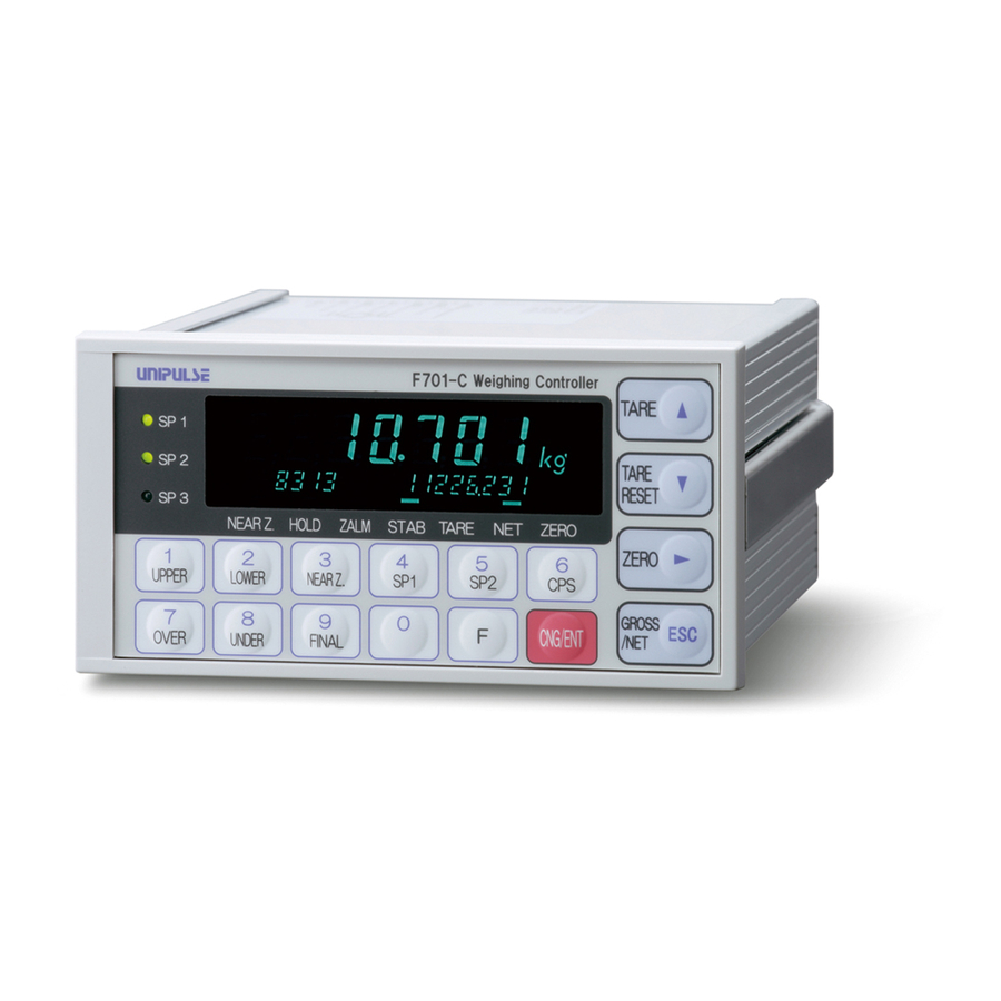
1.APPEARANCE DESCRIPTION 1. APPEARANCE DESCRIPTION 1-1. Front Panel ① Main display ③ Unit indication ② Subdisplay ④ Status display ⑥ Function keys ⑤ Setting keys ① Main display The following three types are displayed. (1) Weight value display Displays the Gross weight or the Net weight. When error occurred, the display shows error and weight value alternately. - Page 13 1.APPEARANCE DESCRIPTION ② Subdisplay Weighing data, such as Accumulation Value, and various setting values are displayed by setting. * Please refer to "- Function Selection" on P.32, "5-2.Subdisplay Selection" on P.56. (1) Accumulation Count, Accumulation Value Accumulation Count Accumulation Value (2) Latest Accumulation Data, Accumulation Value Latest Accumulation Data Accumulation Value...
-
Page 14: Status Display
1.APPEARANCE DESCRIPTION Accumulation Count Displays the count accumulated by the auto accumulation command or external input/output signal, or through RS-232C communication, etc. Accumulation Value Displays the value accumulated by the auto accumulation command or external input/output signal, or through RS-232C communication, etc. Latest Accumulation Data Displays the latest data accumulated by the auto accumulation command or external input/output signal, or through RS-232C... -
Page 15: Function Keys
1.APPEARANCE DESCRIPTION ZERO - Lights at a true zero point (0±1/4 scale division). (When the 1/4 scale division display is OFF under Function Selection in setting mode 3.) - Lights at a true zero point (0±1/4 scale division), “ ” ZERO and at the central point of the scale interval of the indicated value (indicated value ±1/4 ×... - Page 16 1.APPEARANCE DESCRIPTION When → is pressed, Gross is zeroed CNG/ENT ZERO ZERO immediately. (In setting mode 0) However, if this operation is performed with Gross out of the DZ Regulation Value, “ ” flashes. ZALM (For details of the DZ Regulation Value, refer to "5-10.Zero Regulation Value"...
-
Page 17: Rear Panel
1.APPEARANCE DESCRIPTION 1-2. Rear Panel ① AC power input terminal block ⑨ Option space ② Protective ground ③ Frame ground ④ Control connector ⑤ RS-232C connector ⑦ LOCK switch ⑥ SI/F terminal block ⑧ Load cell input terminal block ① AC power input terminal block Connect AC power code. - Page 18 RS-232C connector for receiving and transmitting weight data and status information. The applicable connector is JAE DE-09SN or its equivalent. ⑥ SI/F terminal block 2-wire serial interface is to connect unipulse peripheral equipment such as printer, remote display or data converter. ⑦ LOCK switch LOCK switch for avoiding changes of setting value, it prohibits to change setting value while the switch is ON.
-
Page 19: 2.Connection
2.CONNECTION 2. CONNECTION 2-1. Load cell Connection The voltage application of F701-C is 10V, and the maximum current is 120mA, to which up to four 350Ω load cells can be connected in parallel. Load cell terminal block Load cell terminal block pin assignments Pin No. - Page 20 1) Peel the sheath of the wire to be connected 5mm. 2) Twist the end to such an extent that it will not become loose. 3) Remove the terminal block from the F701-C body with a strong pull. 4) Loosen the screw with a screwdriver to open the hole.
-
Page 21: 6-Wire Connection
2.CONNECTION 2-1-1. 6-wire Connection The load cell input of the F701-C is a 6-wire (remote sense) connection. 6-wire shielded load cell cable should be used and kept separate from AC or other noise generating wire. Load cell +EXC -EXC -OUT... -
Page 22: Connecting Load Cells In Parallel
2.CONNECTION 2-1-3. Connecting Load cells in Parallel In some industrial weighing apparatus, two or more load cells may be connected in parallel to form a hopper scale or track scale. The manner of connection is shown below. Parallel connection can simply be made by using the optionally available B410 (summing box for 4-point multi load cell). -
Page 23: Connection Of The Power Input Terminals
7A. For use at voltages exceeding the rating and for overseas use, have a separate AC cable prepared. - Since the F701-C has no power switch, install a breaker. - Be sure to ground the protective ground terminal to prevent electric shocks. -
Page 24: Si/F Connection
2.CONNECTION 2-4. SI/F Connection The SI/F allows connection of up to three nonpolarized external devices. As for wire materials, use parallel 2-core cables, cabtyre cables, or the like. Connect to the cage clamp type terminal block by using the attached mini screwdriver. 1) Strip the casing 0.2in (6mm) on the cable to be connected. -
Page 25: Connection Of The Control Connector
2.CONNECTION 2-5. Connection of the Control Connector Connect to the control connector (rear panel “CONTROL”). The applicable connector is the following (accessory) manufactured by Fujitsu Component or an equivalent: Connector : FCN-361J024-AU Cover : FCN-360C024-B 2-5-1. Control Connector-Pin Assignment For details, please refer to "9.EXTERNAL INPUT/OUTPUT SIGNALS (CONTROL CONNECTOR)"... -
Page 26: How To Assemble The Connector
2.CONNECTION 2-5-2. How to Assemble the Connector Nut M2 (four) Pan-head machine screw Pan-head machine screw M2×10 (long) (two) M2×8 (short) (two) Washer (two) Case (two) Connector Screw (two) (1) Set the connector and screws (two) into the grooves of the case (one side). (2) Cover with the other case, and fit the cases. -
Page 27: Equivalent Circuit (Input)
A signal is inputted to the signal input circuit by short-circuiting or opening the input terminal and the COM terminal. Short-circuiting is effected by means of a contact (such as a relay or a switch) or a noncontact (such as a transistor or an open-collector TTL). Open F701-C +12V Inside Short Approx. -
Page 28: 3.Methods Of Setting
3.METHODS OF SETTING 3. METHODS OF SETTING 3-1. Setting Procedure Change settings in the order of “setting mode selection” → “setting item selection” → “setting value entry”. 3-1-1. Method of Selecting a Setting Mode In the text, the method of selecting a setting mode is described as follows: (Example) For selecting setting mode 3 →... - Page 29 3.METHODS OF SETTING 3) Select the setting mode number. ( NEAR Z. The input number blinks. Setting mode number 4) Press the key. CNG/ENT The selected setting mode number and weight value are displayed (Setting mode display). Present weight value Setting mode number By pressing the key when the setting mode number is displayed, you...
-
Page 30: Method Of Entering A Setting Value
3.METHODS OF SETTING 3-1-2. Method of Entering a Setting Value In the text, the method of entering a setting value is described as follows: (Example 1) For setting the Balance Weight Value to 50.00kg (Setting by numerical input: Unsigned) → →... - Page 31 3.METHODS OF SETTING (Example 2) For setting the Compensation to -0.30kg (Setting by numerical input: Signed) 6 → → → CNG/ENT CNG/ENT This operation can be performed by the following procedure. * However, it is assumed that setting mode 0 has already been selected. 1) Select the setting item.
- Page 32 3.METHODS OF SETTING (Example 3) For setting the 1/4 scale division display to OFF (Setting from choices) → → → CNG/ENT ZERO ZERO ZERO CNG/ENT OVER This operation can be performed by the following procedure. * However, it is assumed that setting mode 3 has already been selected. 1) Select the setting item.
- Page 33 3.METHODS OF SETTING 4) Select from choices. (Since the 1/4 scale division display should be turned off, press The blinking digit moves to the lower one. Since the blinking digit moves every time key is pressed, setting can be ZERO 1/4 scale division display redone again and again.
-
Page 34: Setting Mode
3.METHODS OF SETTING 3-2. Setting Mode Setting mode 0 Setting mode 1 Setting mode 2 Setting mode 3 Upper Limit Comparison Inhibit Time Weighing Function 1 Balance Weight Value / P.24 / P.26 / P.28 / P.31 UPPER Lower Limit Judging Time Weighing Function 2 Capacity... -
Page 35: Setting Mode 0
3.METHODS OF SETTING 3-2-1. Setting Mode 0 In setting mode 0, setting values for final discharging control are to be set. - Upper Limit (0 ~ 99999) UPPER (For details, please refer to "6-6" on P.90.) - Lower Limit (0 ~ 99999) LOWER (For details, please refer to "6-6"... - Page 36 3.METHODS OF SETTING - Over (0 ~ 999) OVER (For details, please refer to "6-4" on P.86.) - Under (0 ~ 999) UNDER (For details, please refer to "6-4" on P.86.) - Final (0 ~ 99999) FINAL (For details, please refer to "6-4" on P.86.)
-
Page 37: Setting Mode 1
3.METHODS OF SETTING 3-2-2. Setting Mode 1 In setting mode 1, output signals for final discharging control and parameters in sequence mode, etc., are to be set. - Comparison Inhibit Time sec. (0.00 ~ 9.99) . UPPER (For details, please refer to "6-8" on P.93.) - Judging Time sec. - Page 38 3.METHODS OF SETTING - Auto Free Fall Compensation Regulation (0 ~ 99999) OVER (For details, please refer to "6-3" on P.83.) - Analog Filter (0 ~ 3) UNDER (For details, please refer to "5-4" on P.57.) - Tare Weight (0 ~ 99999) FINAL (For details, please refer to "5-13"...
-
Page 39: Setting Mode 2
3.METHODS OF SETTING 3-2-3. Setting Mode 2 In setting mode 2, the display and internal functions of the F701-C are to be tuned. - Weighing Function 1 UPPER Discharging control mode Near Zero comparison 2 : External selection 4 : ON when |Net weight| ≦ Near Zero... - Page 40 3.METHODS OF SETTING - Weighing Function 3 NEAR Z. 1 : Negative Compensation 1 : Digital tare subtraction Effect 0 : Negative Compensation 0 : Digital tare subtraction Inhibit (For details, please refer to (For details, please refer to "5-13" on P.65.) "6-5"...
- Page 41 3.METHODS OF SETTING - Function Key Invalid [TARE] key [GROSS / NET] key 1 : Valid 1 : Valid 0 : Invalid 0 : Invalid [TARE RESET] key [ZERO] key 1 : Valid 1 : Valid 0 : Invalid 0 : Invalid (For details, please refer to "5-17"...
-
Page 42: Setting Mode 3
3.METHODS OF SETTING 3-2-4. Setting Mode 3 In setting mode 3, setting values relating to initial calibration are to be set. - Balance Weight Value (0 ~ 99999) UPPER (For details, please refer to "4-4-6" on P.48.) - Capacity (0 ~ 99999) LOWER (For details, please refer to "4-4-4"... - Page 43 "5-1" on P.55.) Request When using the F701-C for any balance weight to undergo type approval by the Measurement Law, set the 1/4 scale division display to OFF. If it is set to OFF, the “zero point” lights only at a true zero point (0±1/4 scale division).
-
Page 44: Setting Mode 4
3.METHODS OF SETTING 3-2-5. Setting Mode 4 In setting mode 4, setting values relating to communication are to be set. - D/A Output Mode UPPER Test mode Output mode 2 : 20mA fixed output 1 : Net weight 1 : 4mA fixed output 0 : Gross weight 0 : Tied to the weight value (For details, please refer to "10-4-3"... - Page 45 3.METHODS OF SETTING - ID Number (0 ~ 9999) (For details, please refer to "10-5-4" on P.148.) - RS-232C I/F Baud rate Communication mode 5 : 38400bps 7 : Communication mode 6 4 : 19200bps 6 : Communication mode 5 3 : 9600bps 5 : Communication mode 4 2 : 4800bps...
- Page 46 3.METHODS OF SETTING - External Function Selection OVER BCD data update rate At discharging weighing time 1 times/sec. 1 : Net weight is displayed with 2 times/sec. the sign not reversed. 5 times/sec. 0 : Net weight is displayed with 4 : 10 times/sec.
-
Page 47: Setting Mode 5
3.METHODS OF SETTING 3-2-6. Setting Mode 5 - Input Selection UPPER Input selection 4 (B5 pin) Input selection 1 (B2 pin) 6 : Accumulation Clear 6 : Accumulation Clear 5 : Accumulation Command 5 : Accumulation Command 4 : Stop 4 : Stop 3 : Start 3 : Start... - Page 48 3.METHODS OF SETTING - CC-Link I/F Number of occupied station & Transmission speed NEAR Z * Not defined Transmission speed 4 : 10M Number of occupied station 3 : 5M 2 : Occupies 4 stations 2 : 2.5M 1 : Occupies 2 stations 1 : 625k 0 : Occupies 1 station 0 : 156k...
-
Page 49: Setting Mode 8
3.METHODS OF SETTING 3-2-7. Setting Mode 8 In setting mode 8, statistical data having been accumulated in the F701-C is displayed, including Average Weight, Max.Value, Min. Value, General Standard Deviation, Sample Standard Deviation, Accumulation Count, Latest Accumulation Data, Max. - Min. - Page 50 3.METHODS OF SETTING - Max. - Min. (R) (0 ~ 99999) UNDER - Optional Board FINAL BCD parallel data CC-Link interface output interface 1 : Mounted 1 : Mounted 0 : Not mounted 0 : Not mounted RS-485 communication interface D/A converter 1 : Mounted 1 : Mounted...
- Page 51 3.METHODS OF SETTING 【Example】 Times Accumu Actual Average Max. General Sample Max. Min. lation weighing S.D. S.D. - Min. value (Latest Accumulation Data) 0.000 0.000 0.000 0.000 0.000 0.000 error error 20.050 20.050 20.050 20.050 20.050 0.000 0.000 error 40.090 20.040 20.045 20.050...
-
Page 52: 4.Calibration
4. CALIBRATION 4-1. Span Calibration Calibration is performed for matching the F701-C to a load cell. For example, it is work to adjust so that the F701-C accurately displays 100.00kg when an actual load (or weight) of 100kg is applied to the load cell (balance section) of the weighing apparatus to which the F701-C is connected. -
Page 53: Span Calibration Procedure
4.CALIBRATION 4-2. Span Calibration Procedure Follow the steps below to perform Span Calibration. Release calibration inhibit LOCK by the switch OFF on the rear LOCK Switch OFF panel. Release Calibration LOCK Release Setting Value LOCK which inhibits the calibration. The displayed unit is set. Unit Decimal Place Register the position of decimal point. -
Page 54: Secondary Calibration Procedure (Equivalent Calibration)
Calibration procedure performed by entering the rated output value (mV/V) and rated capacity value of load cell without using real load. Secondary calibration function is provided for provisional calibration when the F701-C develops trouble or the calibration value is mistakenly changed. - Page 55 4.CALIBRATION Request - Set the Balance Weight Value to the Capacity or less. - For performing calibration at the rated value according to the specifications of the load cell, set the Capacity to the same value as the rated value of the load cell.
-
Page 56: Preparation For Calibration
4-4. Preparation for Calibration 4-4-1. LOCK Release F701-C features a LOCK function for disabling changes in calibration and setting values. The software LOCK is performed with the operation on the display; the hardware LOCK is located on rear panel. Release both of locks when the calibration is performed. -
Page 57: Unit
CNG/ENT CNG/ENT NEAR Z. 2) Select a desired decimal place. (7-Function Selection) → → → CNG/ENT CNG/ENT ZERO ZERO OVER Decimal place In the F701-C, the decimal place is all fixed except for weight-related descriptions. * It cannot be changed. -
Page 58: Capacity
4.CALIBRATION 4-4-4. Capacity Register the maximum capacity of the scale. If the registered value exceeds by 9 scale divisions, display shows over scale, “ ”. (Input range / 0 ~ 99999) Operation 1) Select setting mode 3. → → → CNG/ENT CNG/ENT NEAR Z. -
Page 59: Balance Weight Value
4.CALIBRATION 4-4-6. Balance Weight Value Register the value of load (balance weight) before the Span Calibration. (Input range / 0 ~ 99999) Operation 1) Select setting mode 3. → → → CNG/ENT CNG/ENT NEAR Z. 2) Input the Balance Weight Value. (1-Balance Weight Value) →... - Page 60 4.CALIBRATION 3) If the Area number is set at 00, input Acceleration. (9-Gravitational Acceleration : acceleration input) → → → CNG/ENT CNG/ENT FINAL Acceleration (9.700 ~ 9.999) If the area number is set at 00, Gravitational Acceleration (Acceleration input) becomes valid. Gravitational acceleration correction table 9.806 9.805...
-
Page 61: 1/4 Scale Division
4.CALIBRATION 4-4-8. 1/4 Scale Division It divides the minimum scale division into four (4) parts. The “ ” (center zero) lamp turns on ZERO when the weight is between +1/4 division and -1/4 division. 1/4 scale division selects ON/OFF. Operation 1) Select setting mode 3. -
Page 62: Zero Calibration
4.CALIBRATION 4-5. Zero Calibration Register initial zero point. - Verify there are no excess loads applied to load cell (or scale). - Check that “ ” is ON. (Correct calibration can not be completed if signal is unstable.) STAB Operation 1) Select setting mode 9 (Calibration mode). - Page 63 4.CALIBRATION - This table is for a 350 Ω load cell. - The temperature coefficient of the connected resistor directly influences the accuracy of the controller. Use a resistance having a temperature coefficient of 50ppm/ ℃ or more (recommended value of about 5ppm/ ℃ ). Resistance Strain Calculated value...
-
Page 64: Span Calibration
Span Calibration means putting a load (test weight) on the load cell (or scale) and calibrating so the F701-C indicates correct weight. - Put the Balance Weight Value which is set the Balance Weight Value, on the load cell (or scale). -
Page 65: Secondary Calibration (Equivalent Calibration)
4.CALIBRATION 4-7. Secondary Calibration (Equivalent Calibration) By key-inputting the weight value corresponding to the output value (mV/V) of the load cell, calibration is performed so that the input of the entered output value results in the entered weight value display. Operation 1) Select setting mode 3. -
Page 66: 5. Function Settings
5.FUNCTION SETTINGS 5. FUNCTION SETTINGS 5-1. Display Frequency Select the F701-C display frequency. The numbers of updates on the display per second is only selected here. Internal A/D conversion speed and CPU processing speed are not changed. The available display frequencies are: 25, 13, 6 or 3 times/sec.. -
Page 67: Subdisplay Selection
5.FUNCTION SETTINGS 5-2. Subdisplay Selection Set the data to be displayed in the subdisplay area. What is displayed in the subdisplay area is the data set here out of: Near Zero/Upper Limit/Lower Limit; Final/Over/Under; Accumulation Count/Latest Accumulation Data/Final; Latest Accumulation Data/Accumulation Value; Accumulation Count/Accumulation Value;... -
Page 68: Analog Filter
When indicated value is stable, this function automatically insert the Digital Filter for restraining the instability. Select whether inserts it or not. Regarding the definition of stability, refer to "5-6.Motion Detection (MD)" on P.58. Stab OFF or filter is not F701-C inserted in stable condition. Analog Digital... -
Page 69: Motion Detection (Md)
5.FUNCTION SETTINGS 5-6. Motion Detection (MD) Set the parameter to detect the stability of the indicated value. When the range of weight changes is within the set range and the status lasts for set period of time, the Stab. turns ON considering to be the weight stable. There are stable mode and checker mode in Motion Detection. - Page 70 5.FUNCTION SETTINGS When the Stab. is ON, it enables to insert the Digital Filter to restrain the instability of weight value. (Please refer to "5-5.Filter in Stable Condition" on P.57.) Stab OFF Analog Digital Digital Comparator Filter Filter Filter Cutoff Counts selectable Stab.
-
Page 71: Zero Tracking (Zt)
5.FUNCTION SETTINGS 5-7. Zero Tracking (ZT) This function automatically adjusts slow drifts and slight shifting of the zero point due to small amounts of accumulation on a scale. - Zero Tracking adjusts the zero point every set period when the shifting of the zero point is within the set point. -
Page 72: Digital Zero (Dz)
5.FUNCTION SETTINGS 5-8. Digital Zero (DZ) The Gross weight is forcibly zeroed by this function. The Net weight changes according to the following expression: (Net weight) = (Gross weight) - (Tare weight). If the digital zero operation is performed where Gross weight exceeds the DZ Regulation Value (Please refer to "5-10.Zero Regulation Value"... -
Page 73: Digital Zero Clear
5.FUNCTION SETTINGS 5-9. Digital Zero Clear This function clears the digital zero. If this operation is performed when “ ” flashes, the digital zero is cleared, and “ ” goes ZALM ZALM out. Operation 1) By selecting setting mode 9 (Calibration mode), the digital zero is cleared. →... -
Page 74: One-Touch Tare Subtraction
5.FUNCTION SETTINGS 5-11. One-touch Tare Subtraction Tare is subtracted and Net weight is zeroed by pressing key. TARE However, the operation is performed only when “ ” is on depending on the setting of STAB Restriction on the Tare Subtraction Function in setting mode 4. The range of Tare subtraction can be selected from all range or 0 <... -
Page 75: One-Touch Tare Subtraction Reset
5.FUNCTION SETTINGS 5-12. One-touch Tare Subtraction Reset The subtracted Tare can be restored and Net weight becomes equal to Gross weight. Operation TARE 1) Press RESET 2) “ ” goes out. TARE - Tare subtraction reset by external signal By short-circuiting A5pin (Tare subtraction OFF) and COM on the control connector, Tare subtraction is immediately reset, and Net weight and Gross weight are equalized. -
Page 76: Digital Tare Subtraction
5.FUNCTION SETTINGS 5-13. Digital Tare Subtraction Tare is subtracted and Net weight is zeroed. Set Tare Weight by pressing key then set digital tare subtraction ON. TARE a) Digital tare subtraction (Select from ON/OFF) b) Tare Weight (Input range / 0 ~ 99999) Operation 1) Select setting mode 2. -
Page 77: Restriction Of The Tare Subtraction Function
5.FUNCTION SETTINGS 5-14. Restriction of the Tare Subtraction Function It can be restricted the function of digital tare subtraction or one touch tare subtraction. a) One-touch tare subtraction (Select from Regularly / In stable mode) acceptance condition It displays the timing of the Tare subtraction. b) Range of tare subtraction (Whole range or from 0 <... -
Page 78: Switching Gross Weight/Net Weight Display
5.FUNCTION SETTINGS 5-15. Switching Gross Weight/Net Weight Display The switching Gross weight/Net weight is executed by pressing on the main display. It can GROSS ESC /NET be switched over ON/OFF by using the signal from control connector to avoid false operation on the display. -
Page 79: Reversing Symbol At Discharging Control
5.FUNCTION SETTINGS 5-16. Reversing Symbol at Discharging Control When discharging a fixed quantity material from material bin, Net weight becomes negative. Discharging weight can be revised to positive by reversing the polarity of Net weight. Select from Net weight with - sign ON or Net weight with - sign OFF. Operation 1) Select setting mode 4. -
Page 80: 6.Discharging Control Mode
The discharging control means the control method for discharging raw material from the hopper or tank. F701-C enables to discharge accurate quantity with the proper combination of setting the control of Final, Set Point 2, Set Point 1, Compensation and Judging Over, Under, Go and Timer for Comparison Inhibit, Judging. - Page 81 Completion of discharge is confirmed with the Near Zero signal. In weighing from the second time onward, (1) ~ (5) are repeated. The feeding valves and discharge valves should be opened and closed through the sequencer or relay sequence according to the control signals from the F701-C.
- Page 82 6.DISCHARGING CONTROL MODE Over Final Final – CPS Under Final – SP2 Final – SP1 Near Zero TIME Tare subtraction Comparison Inhibit Timer Judging Timer Near Zero Judgment (Go, Over or Under)
-
Page 83: Discharging Weighing
Final - Compensation, when one measurement is completed. When the weighing tank runs short, the feeding valves are to be opened to replenish the weighing tank with raw materials from the material tank to weigh. F701-C... - Page 84 The feeding valves and discharge valves should be opened and closed through the sequencer or relay sequence according to the control signals from the F701-C.
- Page 85 6.DISCHARGING CONTROL MODE Gross for Upper/Lower limit comparison, and Net for Final, Set Point 2, and Near Zero comparisons. GROSS (In discharging weighing, Net is compared negatively.) Raw materials are fed until the upper limit signal is output. Lower Limit TIME Final –...
-
Page 86: Discharging Mode
6.DISCHARGING CONTROL MODE Discharging Mode 6-1-3. Set the feeding or discharging. Selectable methods are feeding control, discharging control and external selection (Changing the feed/Discharge by the signal from control connector). Operation 1) Select setting mode 2. → → → CNG/ENT CNG/ENT LOWER 2) Select Discharging control mode. -
Page 87: Simple Comparison Control And Sequence Control
6.DISCHARGING CONTROL MODE 6-2. Simple Comparison Control and Sequence Control 6-2-1. Simple Comparison Compares weight value with discharging value regulerly. Output is always ON when the weight value satisfies the conditions of final discharging setting items. In simple comparison control, the next weighing is judged to be possible when the weight falls short of 25% of the Final after completion of the previous weighing. -
Page 88: Sequential Control
6.DISCHARGING CONTROL MODE ● The Over/Under comparison timing depends on the Over/Under comparison mode setting (Weighing Function 2 in setting mode 2). (It is set at “Regularly” in the illustration.) ● The completion signal output timing depends on the complete signal output mode setting (Weighing Function 2 in setting mode 2). - Page 89 6.DISCHARGING CONTROL MODE ① Normal sequence control (with Over/Under judgment) Over Final Under Final – CPS Final – SP2 Final – SP1 Near Zero TIME Tare Subtraction Start Stop Complete Judgment (Over, Go or Under) Comparison Inhibiti Timer Judging Timer Complete Timer HOLD Near Zero...
- Page 90 6.DISCHARGING CONTROL MODE ● t1 : Comparison Inhibit Time Comparison Inhibit Time in setting mode 1 t2 : Judging Time Judging Time in setting mode 1 t3 : Complete Output Time Complete Output Time in setting mode 1 ● Conditional expression - Near Zero turns ON when Weight value ≦...
- Page 91 6.DISCHARGING CONTROL MODE ● The completion signal output timing is such that the complete signal output mode setting (Weighing Function 2 in setting mode 2) is ignored, but it is output at the OFF edge (ON → OFF) of the final signal (Set Point 3 signal). ●...
- Page 92 6.DISCHARGING CONTROL MODE ● t1 : Comparison Inhibit Time Comparison Inhibit Time in setting mode 1 t2 : Judging Time Judging Time in setting mode 1 t3 : Completion output time Completion Output Time in setting mode 1 t4 : Adjust Feeding Time Adjust Feeding Time in setting mode 1 About the stop signal START...
-
Page 93: Sequence Mode
6.DISCHARGING CONTROL MODE START STOP Sequence error * ● For resetting the sequence error ( * ), input the ON edge (OFF → ON) of the stop signal. The start signal is not received at the time of a sequence error. Sequence Mode 6-2-3. -
Page 94: Auto Free Fall Compensation Regulation
× C F701-C can regulate the value of D for minimizing the errors. When D is within the range of (Final + AFFC.) ≧ Actual weight ≧ (Final - AFFC.), F701-C processes auto free fall compensation. And when compensation feeding is ON in Sequence Mode, F701-C samples the weight value before compensation feeding. - Page 95 6.DISCHARGING CONTROL MODE Example) Final 20.000 AFFC. 0.100 Average count of AFFC. AFFC. coefficient Times Actual Error Average count of Weighing AFFC. When negative CPS When negative CPS is inhibit. is effect. ← Power ON 20.050 +0.050 0.500 -0.033 20.040 +0.040 0.500 -0.033...
- Page 96 6.DISCHARGING CONTROL MODE Setting compensation parameter a) AFFC. Set the regulated value to avoid the compensation value becomes extremely large (or small). (Input range / 0 ~ 99999) b) AFFC. ON/OFF Selection of AFFC. When CC-Link is installed, writing of free fall compensation data can be prohibited, at the time of writing in the exclusive data area.
-
Page 97: Final / Set Point 2 / Set Point 1 / Compensation / Over / Under
6.DISCHARGING CONTROL MODE 6-4. Final / Set Point 2 / Set Point 1 / Compensation / Over / Under Setting for controlling and judging the discharge. WEIGHT Over Final Final – CPS Under Final – SP2 Final – SP1 Near Zero TIME Near Zero Over... - Page 98 6.DISCHARGING CONTROL MODE a) Final (Input range / 0 ~ 99999) b) Set Point 2 (Input range / 0 ~ 99999) c) Set Point 1 (Input range / 0 ~ 99999) d) Compensation (Input range / 0 ~ 9999: When negative compensation is inhibit) (Input range / -9999 ~ 9999: When negative compensation is effect) e) Over (Input range / 0 ~ 999)
- Page 99 6.DISCHARGING CONTROL MODE 1) Select setting mode 0. → → → CNG/ENT CNG/ENT 2) Input the Set Point 1. (4-Set Point 1) → → → CNG/ENT CNG/ENT Set Point 1 (0 ~ 99999) 1) Select setting mode 0. → → →...
-
Page 100: Negative Compensation
6.DISCHARGING CONTROL MODE 6-5. Negative Compensation The selection whether the negative value of input range of compensation is including or not. Select from Effect/ Inhibit. - Inhibit ....Not including the negative value of the input range of compensation. (Input range is 0 ~ 9999.) - Effect .....Including the negative value of the input range of compensation. -
Page 101: Near Zero / Upper Limit / Lower Limit
6.DISCHARGING CONTROL MODE 6-6. Near Zero / Upper Limit / Lower Limit Setting for judging the final discharging function. 〈 Conditional formula 〉 a) Near Zero Weight value ≦ Near Zero (Input range / 0 ~ 99999) b) Upper Limit Weight value >... -
Page 102: Upper/Lower Limit Comparison / Upper/Lower Limit Comparison Mode / Near Zero Comparison / Final And Comparison / Over/Under Comparison Mode
6.DISCHARGING CONTROL MODE 6-7. Upper/Lower Limit Comparison / Upper/Lower Limit Comparison Mode / Near Zero Comparison / Final and Comparison / Over/Under Comparison Mode It enables to select the weight (Gross/Net) to be compared and the timing of comparison at the each comparison point of Upper/Lower limit, Near Zero or Over/Under. - Page 103 6.DISCHARGING CONTROL MODE b), e) 1) Select setting mode 2. → → → CNG/ENT CNG/ENT LOWER 2) Set Upper/Lower limit comparison mode and Over/Under comparison mode. (2-Weighing Function 2) → → → CNG/ENT CNG/ENT ZERO ZERO LOWER Over/Under comparison mode Upper/Lower limit comparison mode 3 : Comparison is made, and the...
-
Page 104: Complete Signal Output Mode / Complete Output Time / Judging Time / Comparison Inhibit Time / Output Selection 2
6.DISCHARGING CONTROL MODE 6-8. Complete Signal Output Mode / Complete Output Time / Judging Time / Comparison Inhibit Time / Output Selection 2 - Comparison Inhibit Time/Judging Time The function which inhibits the comparison for certain period of time to eliminate false control or judgement with the vibration caused by opening or closing of valve. - Page 105 6.DISCHARGING CONTROL MODE a) Complete signal output mode (Select from Judging Time / Judge & Stable / Judging / Stable) b) Complete Output Time Input range / 0.00 ~ 9.99 c) Judging Time Input range / 0.00 ~ 9.99 d) Comparison Inhibit Time Input range / 0.00 ~ 9.99 e) Output Selection 2 Select from Go output / Complete output...
- Page 106 6.DISCHARGING CONTROL MODE 1) Select setting mode 1. → → → CNG/ENT CNG/ENT UPPER 2) Input the Judging Time. (2-Judging Time) → → → CNG/ENT CNG/ENT LOWER Judging Time (sec.) (0.00 ~ 9.99) 1) Select setting mode 1. → → →...
-
Page 107: Judging Times / Az Times / At Start Near Zero Confirmation / At Start Weight Value Confirmation / Adjust Feeding / Adjust Feeding Time
The auto free fall compensation function stores compensation samples by using the Over/Under judgment signals. If the number of Judging Times is set to 00 (no judgment), the F701-C cannot store such samples for auto free fall compensation, so that the compensation function does not work. - Page 108 6.DISCHARGING CONTROL MODE b) AZ times The selection whether the weight value is set 0 or not at start. When weight value = Gross weight, conduct digital zero or when weight value = Net weight, subtract the Tare to set weight value for 0. Set the number from 00 to 99.
- Page 109 6.DISCHARGING CONTROL MODE d) Weight value confirmation at the start of weighing Confirm whether the weighing value has reached SP1 at the start of weighing. (select from ON or OFF) If it has, “ ” will be displayed. Refer to "6-4.Final / Set Point 2 / Set Point 1 / Compensation / Over / Under" on P.86 concerning Set Point 1 setting.
- Page 110 6.DISCHARGING CONTROL MODE c), d), e) 1) Select setting mode 2. → → → CNG/ENT CNG/ENT LOWER 2) Set Near Zero check at start-time, weight value check at start-time and adjust feeding. (4- Sequence Mode) → → → CNG/ENT CNG/ENT ZERO (Sequence control) 1 : At start-time, weight value...
-
Page 111: Net Over / Gross Over
6.DISCHARGING CONTROL MODE 6-10. Net Over / Gross Over This function warns you that the Net or Gross weight exceeds the entered control value. a) Net Over (Input range / 0 ~ 99999) b) Gross Over (Input range / 0 ~ 99999) Conditional formula Display Net Over... -
Page 112: Weight Error / Sequence Error
6.DISCHARGING CONTROL MODE 6-11. Weight Error / Sequence Error Weight error When the display is LOAD, OFL or ZALM, the output turns ON. Sequence error When the display is Err, the output turns ON. Weight error and sequence error output signals are selectable by setting. Operation 1) Select setting mode 5. -
Page 113: 7. Statistical And Accumulation Function Setting And Operation
7.STATISTICAL AND ACCUMULATION FUNCTION SETTING AND OPERATION 7. STATISTICAL AND ACCUMULATION FUNCTION SETTING AND OPERATION Weight values are accumulated by this function. Based on the accumulated weight data, statistical data, such as the maximum, minimum, and average, are calculated. Weight values can be accumulated by the auto accumulation command or external input/output signal, through RS-232C communication, RS-485 communication (option), CC-Link (option). -
Page 114: Data Display
7.STATISTICAL AND ACCUMULATION FUNCTION SETTING AND OPERATION 7-1. Data Display The statistics data accumulated in F701-C are displayed. Weight values can be accumulated by weighing with the auto accumulation command ON or by turning ON the external signal input “Accumulation command”. - Page 115 Accumulation command through the RS-232C or RS-485 (option) An immediate accumulation is executed when the accumulation command “CI” is received from the host. Host F701-C * No return data Accumulation command through the CC-Link (option) Accumulation is executed by using the bit of RY0018 *.
-
Page 116: Accumulation Clear
7.STATISTICAL AND ACCUMULATION FUNCTION SETTING AND OPERATION 7-3. Accumulation Clear Clear Accumulated Data (times, accumulation value and statistical data). Operation 1) Select setting mode 9. → → → CNG/ENT CNG/ENT FINAL 2) Input the password “1235”. (9-Pass Word) → → →... - Page 117 Accumulation clear through the RS-232C or RS-485 (option) Immediate accumulation clearing is executed when the accumulation command “CJ” is received from the host. Host F701-C * No return data Accumulation clear through the CC-Link (option) Accumulation clearing is executed by using the bit of RY0019 *.
-
Page 118: Auto Accumulation Command
Select whether or not to automatically accumulate weight values in the F701-C. If the auto accumu- lation command is on, an accumulation is made when the complete signal of the F701-C turns on. At this time, the count, accumulation value and statistical data are updated, and also an auto print command is sent onto the SI/F format. - Page 119 7.STATISTICAL AND ACCUMULATION FUNCTION SETTING AND OPERATION 2) Sequence control Weighing Value over Final under Final - CPS Final - Setpoint 2 Final - Setpoint 1 Time Tare Start Complete Judging Time Accumulation Regarding Simple Comparison Control and Sequence Control refer to "6-2.Simple Comparison Control and Sequence Control"...
-
Page 120: 8.System Mode
8.SYSTEM MODE 8. SYSTEM MODE 8-1. LOCK (soft) Lock for protecting from false operation, refer to "18.THE LIST OF INITIAL SETTING VALUE" on P.176 regarding effective setting value for LOCK (soft). Select from ON/OFF. Operation 1) Select setting mode 4. →... -
Page 121: Self-Check And Memory Clear
8.SYSTEM MODE 8-3. Self-Check and Memory Clear This equipment is provided with the self-check function by which the memory is automatically checked to detect problems, and the visual check function by which the display can be checked visually. While pressing the key, turn ON the power. -
Page 122: (Control Connector)
9.EXTERNAL INPUT/OUTPUT SIGNALS (CONTROL CONNECTOR) 9. EXTERNAL INPUT/OUTPUT SIGNALS (CONTROL CONNECTOR) The Input/Output circuit and internal circuit are photocoupler-insulated electrically. 9-1. Control Connector-Pin Assignment The applicable connector is the following (accessory) manufactured by Fujitsu Component or an equivalent: Connector: FCN-361J024-AU / Cover: FCN-360C024-B *... -
Page 123: Equivalent Circuit (Input)
A signal is inputted to the signal input circuit by short-circuiting or opening the input terminal and the COM terminal. Short-circuiting is effected by means of a contact (such as a relay or a switch) or a noncontact (such as a transistor or an open-collector TTL). Open F701-C +12V Inside Short approx. -
Page 124: External Input Signal
9.EXTERNAL INPUT/OUTPUT SIGNALS (CONTROL CONNECTOR) 9-4. External Input Signal 9-4-1. Gross/Net Switching (G/N) <Edge Input> <Level Input> Edge input or level input is selectable by the setting of Gross weight/Net weight display (External Function Selection in setting mode 4). * For the method of setting, refer to "5-15.Switching Gross Weight/Net Weight Display" on P.67. - In the case of edge input (G/N setting: internal key mode) When external input is ON edge (OFF →... -
Page 125: Tare Subtraction (Tare On)
9.EXTERNAL INPUT/OUTPUT SIGNALS (CONTROL CONNECTOR) 9-4-3. Tare Subtraction (TARE ON) <Edge Input> Subtract the Tare at once by external input ON edge (OFF → ON), it brings the Net weight to zero. key operation also results in the same movement (when [TARE] key is valid under the TARE Function Key Invalid setting in setting mode 2) However, the operation is performed only when “... -
Page 126: Judge
9.EXTERNAL INPUT/OUTPUT SIGNALS (CONTROL CONNECTOR) 9-4-6. Judge <Level Input> Valid when Over/Under comparison or Upper/Lower limit comparison (Weighing Function 2 in setting mode 2) is set to external judgment input. * For the method of setting, refer to "6-7.Upper/Lower Limit Comparison / Upper/Lower Limit Comparison Mode / Near Zero Comparison / Final and Comparison / Over/Under Comparison Mode"... -
Page 127: Accumulation Command
9.EXTERNAL INPUT/OUTPUT SIGNALS (CONTROL CONNECTOR) 9-4-9. Accumulation command <Edge Input> An immediate accumulation is executed at the ON edge (OFF → ON) of the external input. The weight value (gross or net) set in the over/under comparison mode is accumulated. Pulse width 50msec or more ccumulation Clear 9-4-10. -
Page 128: Input Selection
9.EXTERNAL INPUT/OUTPUT SIGNALS (CONTROL CONNECTOR) 9-4-11. Input Selection On each pin of input selection 1 (B2) to 4 (B5) of the external input/output signals, the input signal can be selected by setting. Settable items are accumulation clear, accumulation command, stop, start, feed/discharge, judge, and hold (common to input selection 1 to 4). -
Page 129: External Output Signal
9.EXTERNAL INPUT/OUTPUT SIGNALS (CONTROL CONNECTOR) 9-5. External Output Signal 9-5-1. Near Zero The output turns ON when Weight value ≦ Set value of Near Zero. Near Zero in setting mode 0 Near zero comparison under Weighing Function 1 in setting mode 2 * For the method of setting, refer to "6-6.Near Zero / Upper Limit / Lower Limit"... -
Page 130: Sequence Error
* For the error display, refer to "11.OVER SCALE & ERROR" on P.157. 9-5-6. RUN This output turns ON when F701-C is ready to operate. RUN can be outputted externally as the signal of output selection 3 by setting. Operation 1) Select setting mode 5. -
Page 131: Sp1, Sp2, Sp3
9.EXTERNAL INPUT/OUTPUT SIGNALS (CONTROL CONNECTOR) 9-5-8. SP1, SP2, SP3 ◆ In simple comparison mode SP1 turns ON when Weight value ≧ Final - SP1 SP2 turns ON when Weight value ≧ Final - SP2 SP3 turns ON when Weight value ≧ Final - CPS Final, Set Point 1, Set Point 2, Compensation in setting mode 0 Final and Over/Under comparison under Weighing Function 1... -
Page 132: Under, Go, Over
9.EXTERNAL INPUT/OUTPUT SIGNALS (CONTROL CONNECTOR) 9-5-9. Under, Go, Over ◆ In simple comparison mode Select comparison mode in Over/Under comparison mode (Weighing Function 2 in setting mode 2). The under signal turns ON when Weight value < Final - Under The over signal turns ON when Weight value >... -
Page 133: Complete
9.EXTERNAL INPUT/OUTPUT SIGNALS (CONTROL CONNECTOR) 9-5-10. Complete ◆ In simple comparison mode Select the complete signal output timing in complete signal output mode (Weighing Function 2 in setting mode 2). The output ON time depends on the Complete Output Time in setting mode 1. * For the method of setting, refer to "6-8.Complete Signal Output Mode / Complete Output Time / Judging Time / Comparison Inhibit Time / Output Selection 2"... -
Page 134: Output Selection
9.EXTERNAL INPUT/OUTPUT SIGNALS (CONTROL CONNECTOR) 9-5-11. Output selection Each signal of the weight error, sequence error, complete, go, RUN, and accumulation error outputs is selective by setting. Weight error and sequence error The weight error and sequence error are outputted from output selection 1 of B9 pin. Complete and Go The complete and go are outputted from output selection 2 of B10 pin. -
Page 135: 10.Interface
10. INTERFACE 10-1. 2-wire Serial Interface (SI/F) This 2-wire serial interface is for connecting the F701-C to peripheral equipment such as a printer or remote display. A two-core parallel cable or a cabtyre cable (Wire with covering thickened for construction) may be used for connection. When a two-core parallel cable or a cabtyre cable is used, the transmitting distance is approximately 30m. -
Page 136: Rs-232C Interface
ASCII 2.Connector pin assignment Adaptable connector : 9-pin D-SUB connector (JAE DE-09SN, OMRON XM3D-0921 etc) * 10-2-2. Cable F701-C personal computer (9-pin) Cross type F701-C personal computer (25-pin) Cross type The above diagram is for connecting a personal computer as a DTE (Data Terminal Equipment) device. -
Page 137: Setting Values For Rs-232C
F701-C. 10-2-4. Communication Mode - Communication mode 0 F701-C communicates with the command from the host computer. The terminator can be selected “CR” or “CR+LF”. - Communication mode 1 F701-C sends Gross weight continuously. - Page 138 F701-C sends Net weight at the timing of auto print command. Command is invalid at this mode. Transmission format 2 (20byte) - Communication mode 6 F701-C sends Gross and Net weight at the timing of auto print command. Command is invalid at this mode. Transmission format 3 (23byte) Request Please refer to each page about following items.
-
Page 139: Transmission Format
10.INTERFACE 10-2-5. Transmission Format - Transmission format 1 9 10 11 12 13 14 15 16 17 18 19 ± CR LF Sign HEADER Gross weight, 5-digit + decimal point + or - - Transmission format 2 9 10 11 12 13 14 15 16 17 18 19 ±... -
Page 140: Communication Format
10-2-6. Communication Format - Reading out the Gross weight (sign, 5-digt weight value, decimal point) Host A CR + CR LF F701-C - Reading out the Net weight (sign, 5-digit weight value, decimal point) Host + CR LF F701-C - Reading out the Tare weight (sign, 5-digit weight value, decimal point) Host +... - Page 141 10.INTERFACE - Reading out the status 2 (7-digit) Host CR LF F701-C Complte output signal output signal Over output signal output signal output signal Under output signal output signal - Reading out the status 3 (7-digit) Host CR LF F701-C...
- Page 142 Error output signal Sequence error 0 or 1 Span calibrating Operation Zero calibrating Same as the error mode Weighing display of F701-C. Calibration error -LOAD 0 or 2 +LOAD Weighting value OFL3 Same as the error Over flow OFL2 display of F701-C.
- Page 143 * For setting value No., refer to "Setting value communication format" on P.134. - Zero Calibration Host 0 CR F701-C Calibrating 0: Normally completed, 1 ~ 9 : Error (same as the error display of F701-C) - Span Calibration Host 0 CR F701-C Calibrating 0: Normally completed, 1 ~ 9 : Error...
- Page 144 10.INTERFACE - Gross weight selection Host F701-C * No return data - Net weight selection Host F701-C * No return data - Tare subtraction Host F701-C * No return data - Tare subtraction reset Host F701-C * No return data...
- Page 145 10.INTERFACE - Setting value communication format Use the following for reading and writing set values. For the communication formats, see p.132. Setting value No. 5-digit setting value (max.) * Where the setting is 0, do not enter other values than 0.
- Page 146 10.INTERFACE Setting value No. 5-digit setting value (max.) * Where the setting is 0, do not enter other values than 0.
- Page 147 10.INTERFACE Setting value No. 5-digit setting value (max.) * Where the setting is 0, do not enter other values than 0.
-
Page 148: Bcd Parallel Data Output Interface
A signal is inputted to the signal input circuit by short-circuiting or opening the input terminal and the COM terminal. Short-circuiting is effected by means of a contact (such as a relay or a switch) or a noncontact (such as a transistor or an open-collector TTL). Open F701-C +12V Inside Short Approx. -
Page 149: Equivalent Circuit (Output)
10.INTERFACE 10-3-3. Equivalent Circuit (Output) The signal output circuit is open-collecter output of TTL. +12V F701-C Vext Inside Outside Vceo=30V(max) Ic =120mA (max) ● Internal transistor status ● Output pin level Output data Negative Positive Output data Negative Positive H... -
Page 150: Over Status Output (Over)
10.INTERFACE 10-3-6. Over Status Output (OVER) When weight values output as BCD data are on the following conditions, 1 (OVER) is output. Weight value Conditional expression Net weight Net weight > Net over setting value Gross weight Gross weight > Gross over setting value Tare weight Tare weight >... -
Page 151: Bcd Data Update Rate Selection
10.INTERFACE 10-3-9. BCD Data Update Rate Selection Operation 1) Select setting mode 4. → → → CNG/ENT CNG/ENT 2) Set the Data update rate. (7-External Function Selection) → → → CNG/ENT CNG/ENT OVER Data update rate 1 times/sec. STROBE range Approx. -
Page 152: D/A Converter
10.INTERFACE 10-4. D/A Converter The D/A converter is an interface to output measured weight values as electrical signals. Current in proportion to the weight value (4mA ~ 20mA) can be output. The over range is ±5% of the full scale. 10-4-1. - Page 153 10.INTERFACE - Taking current output signals Connect an external equipment (load resistance 350Ω or less) between CUR.(+) ~ G(-) of F701-C. F701-C ← Inside Outside → CUR. (+) + External equipment - G (-) Load resistance: 350Ω or less CAUTION Do not apply voltage or current to the current output terminal externally by mistake.
-
Page 154: Specifications
10-4-3. Method of Adjusting the D/A Zero and Gain The D/A converter of the F701-C obtains analog output by setting the weight value to output 4mA of current and the weight value to output 20mA of current, respectively. Input each setting value and select D/A Output Mode in setting mode 4. - Page 155 10.INTERFACE a) D/A Output Mode b) D/A Zero Output Weight (Input range / 0 ~ 99999 or Capacity) c) D/A Full Scale (Input range / 0 ~ 99999 or Capacity) Operation 1) Select setting mode 4. → → → CNG/ENT CNG/ENT 2) Set Test mode and Output mode.
-
Page 156: About D/A Resolution
10.INTERFACE Example When setting is as follows: D/A Output Mode ....01 D/A Zero Output Weight..00500 D/A Full Scale......02500 Current (mA) Resolution 1/10000 2000 2500 D/A Zero Output Weight setting D/A Full Scale setting Current (mA) 3.84 Zero 4.00 1000 8.00... -
Page 157: Communication Interface
- Couple a terminal resistor of 100 ~ 200Ω to the receiving end. - The F701-C side has internal terminal resistor. By turning ON the Rt switch, it is not necessary to install external resistance. -
Page 158: Setting Values For Rs-485
0 : 1200bps Parity bit Character length 2 : Even 1 : 8bit 1 : Odd 0 : 7bit 0 : None 2. The initial set for RS-485 port of connecting personal computer and sequencer should be the same setting of F701-C. -
Page 159: Communication Method
1. For connecting more than one F701-C, assign an ID number to each F701-C. 2. When a start command including an ID number is sent from the host, only one F701-C is brought into transmittable condition, in which reading of weight data, reading and changing of setting values, commands, etc., become valid. -
Page 160: Communication Format
10-5-5. Communication Format - Reading out the Gross weight (sign, 5-digt weight value, decimal point) Host A CR + CR LF F701-C - Reading out the Net weight (sign, 5-digit weight value, decimal point) Host + CR LF F701-C - Reading out the Tare weight (sign, 5-digit weight value, decimal point) Host +... - Page 161 10.INTERFACE - Reading out the status 2 (7-digit) Host CR LF F701-C Complte output signal output signal Over output signal output signal output signal Under output signal output signal - Reading out the status 3 (7-digit) Host CR LF F701-C...
- Page 162 Error output signal Sequence error 0 or 1 Span calibrating Operation Zero calibrating Same as the error mode Weighing display of F701-C. Calibration error -LOAD 0 or 2 +LOAD Weighting value OFL3 Same as the error Over flow OFL2 display of F701-C.
- Page 163 * For setting value No., refer to "Setting value communication format" on P.154. - Zero Calibration Host 0 CR F701-C Calibrating 0: Normally completed, 1 ~ 9 : Error (same as the error display of F701-C) - Span Calibration Host 0 CR F701-C Calibrating 0: Normally completed, 1 ~ 9 : Error...
- Page 164 10.INTERFACE - Gross weight selection Host F701-C * No return data - Net weight selection Host F701-C * No return data - Tare subtraction Host F701-C * No return data - Tare subtraction reset Host F701-C * No return data...
- Page 165 10.INTERFACE - Setting value communication format Use the following for reading and writing set values. For the communication formats, see p.152. Setting value No. 5-digit setting value (max.) * Where the setting is 0, do not enter other values than 0.
- Page 166 10.INTERFACE Setting value No. 5-digit setting value (max.) * Where the setting is 0, do not enter other values than 0.
- Page 167 10.INTERFACE Setting value No. 5-digit setting value (max.) * Where the setting is 0, do not enter other values than 0.
-
Page 168: 11.Over Scale & Error
11.OVER SCALE & ERROR 11. OVER SCALE & ERROR 11-1. Over Scale The weight error output turns ON. The input of A/D converter overflowed Net weight > Net Over set value Gross weight > Capacity + 9 scale division Gross weight > Gross Over set value * Net weight = Gross weight - Tare weight 11-2. -
Page 169: Calibration Error
11.OVER SCALE & ERROR 11-3. Calibration Error Error item Alarm message Re-do Zero Calibration. The initial Tare is beyond the zero adjustment range. The initial Tare is minus. The input balance weight is beyonde the Capacity. The balance weight is “00000”. The load cell output dose not reach the span adjustment range. -
Page 170: 12.Trouble Shooting
Check whether the output of the load cell is within span adjutment range; Check there are breakages in the cable which is connected to the F701-C and the load cell; And whether the load cell connector on the rear panel is open or not, when the load cell input termi- nal block is open (not connected with the load cell) will display “... -
Page 171: Error Display
12.TROUBLE SHOOTING ● Error display (Sequence error) When start signal turns ON, stop signal turns ON. Turn OFF stop signal then start weighing. (Sequence error) During weigh cycle, the stop signal turns ON. Set the stop signal from OFF to ON to resolve the sequence error. (Sequence error) It is displayed if a ZALM condition is brought about when the auto zero is in operation by sequence control. - Page 172 12.TROUBLE SHOOTING (Calibration error) Zero Calibration must be entered again. Zero Calibration should always be done before Span Caibration. If “ ” appears after Calibration, Zero Calibration must be entered again. After Zero Calibration “ ” will disappear. (Calibration error) Initial dead load is above zero adjustment range.
- Page 173 The set Balance Weight Value is “00000”. Set adequate value to Balance Weight Value. (Calibration error) he load cell output dose not reach the span adjustment range of the F701-C. Check how load is applied to load cell; check load cell has sufficient outpul (mV/V) to reach span range.
- Page 174 STAB Calibration. Do Calibration again. The span adjustable range of the F701-C is 0.3 ~ 3.2 (mV/V). Since display to the Capacity is guaranteed in Span Calibration, calibration cannot be performed if the load cell output is under 0.3 (mV/V) ( ) or exceeds 3.2 (mV/V) (...
- Page 175 The setting values stored in the SRAM (refer to "18.THE LIST OF INITIAL SETTING VALUE" on P.176) are backed up by the lithium battery. If the power of the F701-C is turned off with the voltage of the lithium battery having dropped, the setting values are lost.
- Page 176 It is displayed if a checksum error occurs in self-checking or at power-on. (NOV RAM check error) It is displayed if a NOV RAM check error occurs in self-checking. * In the case of self-check error display, the F701-C is faulty. Request repair from your distributor or us.
-
Page 177: 13.Replacement Of The Backup Battery
The life of the lithium battery for memory backup is approx. 7 years. For replacement of the battery, send the F701-C to us in a manner similar to repair. Since the setting values in the “SRAM” (refer to "18.THE LIST OF INITIAL SETTING VALUE" on P.176) are lost when the battery is removed, record the setting values beforehand. -
Page 178: 14.Block Diagram
14.BLOCK DIAGRAM 14. BLOCK DIAGRAM... -
Page 179: 15.Dimensions
15.DIMENSIONS 15. DIMENSIONS Unit:mm... -
Page 180: 16.Mounting On A Panel
16.MOUNTING ON A PANEL 16. MOUNTING ON A PANEL Please follow the procedure for mounting a panel to F701-C. (1) Make a hole in the mounting panel. Unit : mm Panel cutout size 138W×68H (mm) Mounting panel thickness 1.6mm or more (2) Remove the mounting rails on both sides of the controller, and insert the controller into the panel. -
Page 181: 17.Specifications
17.SPECIFICATIONS 17. SPECIFICATIONS 17-1. Analog Section Excitation voltage DC10V±5% Output current : within 120mA Remote sense type (Up to four 350Ω load cells can be connected in parallel.) Zero adjustment range 0 ~ 2mV/V Coarse adjustment: Digital control by course adjustment circuit Fine adjustment: Automatic adjustment by digital operation Gain adjustment range... -
Page 182: Display Section
17.SPECIFICATIONS 17-2. Display Section Display Main display : Numerical display (7-digit) by fluorescent character display tube; 10.4mm in character height Subdisplay : Numerical display (18-digit) by fluorescent character display tube; 4.0mm in character height Indicated value 5-digit, sign: negative display at the highest digit Unit Label attached (t, kg, g, N, lb) Capacity... -
Page 183: External Input/Output
(Emitter = COM terminal) Output LO with transistor ON. 17-5. Interface < Standard equipment > Two-wire serial interface [SI/F] Serial interface to connect a UNIPULSE-manufactured printer, external display, etc. Transmitting method : Asynchronous Transmitting speed : 600bps RS-232C communication interface [232] Writing, changing, reading, etc., of weight data and various types of status, and additionally... - Page 184 17.SPECIFICATIONS Bit configuration : Star : 1bit Character length : 7 or 8bit selectable Stop : 1 or 2bit selectable Parity : None, Odd or Even selectable Code : ASCII < Option > (Number of options mountable: 1) BCD parallel data output interface [BCO] Parallel interface to send weight data to a printer, external display or various sorts of data processing equipment.
-
Page 185: General Performance
CC-Link interface [CCL] Links directly to PLC. CC-Link I/F operates as the remote device stations corresponding to CC-Link Ver.1.10. Refer to F701-C CC-Link I/F specifications for details. 17-6. General Performance Power supply voltage AC100 ~ 240V (+10%, -15%) [free power source 50/60Hz] Power consumption Approx. -
Page 186: Attachment
17.SPECIFICATIONS 17-7. Attachment AC input cord (3m)................1 Minus screw driver (For WAGO terminal)........1 Control signal Input/Output connector ..........1 Connector for BCD output (with BCD option) ......1 Connector for D/A converter (with D/A converter option) ...1 Connector for RS-485 (with the RS-485 option)......1 Connector for CC-Link (with the CC-Link option).......1 Operation manual................1 Jumper line..................2... -
Page 187: 18.The List Of Initial Setting Value
18.THE LIST OF INITIAL SETTING VALUE 18. THE LIST OF INITIAL SETTING VALUE * Initial value : Factory-shipped values. * LOCK 1 : Changing of setting values is inhibited by the software switch (Setting Value LOCK in setting mode 4) (stored in the SRAM). * LOCK 2 : Changing of setting values is inhibited by the software switch (Setting Value LOCK in setting mode 4) (stored in the NOV RAM). -
Page 188: Setting Mode 2
18.THE LIST OF INITIAL SETTING VALUE 18-3. Setting Mode 2 → → → CNG/ENT CNG/ENT LOWER Initial LOCK 1 LOCK 2 LOCK SW Setting item Display value (SRAM) (NOV.RAM) (NOV.RAM) Weighing Function 1 0000 ◎ Weighing Function 2 01000 ◎ Weighing Function 3 00141 ◎... -
Page 189: Setting Mode 5
18.THE LIST OF INITIAL SETTING VALUE 18-6. Setting Mode 5 → → → CNG/ENT CNG/ENT Initial LOCK 1 LOCK 2 LOCK SW Setting item Display value (SRAM) (NOV.RAM) (NOV.RAM) Input Selection 0234 ◎ Output Selection ◎ CC-Link I/F Occupied station & ◎...
Need help?
Do you have a question about the F701-C and is the answer not in the manual?
Questions and answers