
Related Manuals for Rosslare AC-F4 Series


Summary of Contents for Rosslare AC-F4 Series
- Page 1 2013 March AC-F/G4x Family Outdoor Backlit Standalone Controllers Installation and Programming Manual Models: AC-F43 AC-F44 AC-G43 AC-G44 AC-F4x AC-G4x...
- Page 2 ROSSLARE. ROSSLARE reserves the right to revise and change this document at any time, without being obliged to announce such revisions or changes beforehand or after the fact.
-
Page 3: Table Of Contents
Table of Contents Table of Contents Introduction ..............9 Controller Types ..............9 Key Features ................9 Box Content ................. 10 Ancillary Equipment .............. 11 Front Panel Description ............11 Technical Specifications ..........13 Installation ..............14 Mounting the Controller ............14 Wiring the Controller ............ - Page 4 Table of Contents 4.4.3 Tamper Feature ................23 4.4.4 Lockout Feature (Keypad/Card Tamper) ........24 4.4.5 BL-D40 External Sounder .............. 24 Programming ............25 Introduction ................25 5.1.1 Entering the Programming Mode..........27 5.1.2 Exiting the Programming Mode ............ 27 Changing the Open Code ............
- Page 5 Table of Contents 5.13.1 Relay Code Assignment using Standard Method ......47 5.13.2 Relay Code Assignment using Search Method ......48 5.14 Changing PIN Code Length/Factory Default Settings ....49 5.15 Replacing a Programming Code ..........50 5.16 Replacing a Normal/Secure Code ........... 50 Limited Warranty ............
- Page 6 List of Figures List of Figures Figure 1: Front Panel of AC-F4x Series ............. 11 Figure 2: Front Panel of AC-G4x Series ............12 Figure 3: Drilling Holes Identification ............... 14 Figure 4: Wiring Diagram for Lock Strike Relay & REX........16 Figure 5: Wiring Diagram for Auxiliary Input &...
- Page 7 List of Tables List of Tables Table 1: Wiring Color Guide ................15 Table 2: Programming Menus................26 Table 3: Quick Reference Guide for Auxiliary Mode Setting ......35 AC-F/G4x Family Installation and Programming Manual...
- Page 8 The use of the software associated with the system and/or product, if applicable, is subject to the terms of the license provided as part of the purchase documents. ROSSLARE ENTERPRISES LIMITED and/or its related companies and/or subsidiaries’ (hereafter:"ROSSLARE") exclusive warranty and liability is limited to the warranty and liability statement provided in an appendix at the end of this document.
-
Page 9: Introduction
Introduction Introduction The AC-F4x series and AC-G4x series access control units are waterproof standalone controllers. All the units are suitable for both indoor and outdoor mounting. The unit(s) accepts up to 500 users and allows entry via a personal identification number (PIN) and/or by presenting a proximity card. -
Page 10: Box Content
Supplied with mounting template for easy installation Box Content Before beginning, verify that all of the following is in the box. If anything is missing please report the discrepancy to your nearest Rosslare Office. One unit One drilling template (label/sticker) ... -
Page 11: Ancillary Equipment
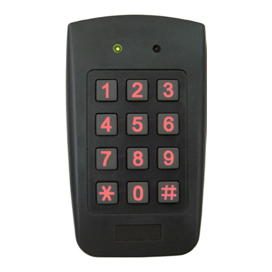
Magnetic contact (optional) – installed for door monitor capabilities. Other Rosslare accessories can be found at Rosslare's Website: www.rosslaresecurity.com F ront Panel Description 1 0 B Figure 1 and Figure 2 show the controls and indicators of all controller versions. -
Page 12: Figure 2: Front Panel Of Ac-G4X Series
Introduction Figure 2: Front Panel of AC-G4x Series AC-F/G4x Family Installation and Programming Manual... -
Page 13: Technical Specifications
Technical Specifications Technical Specifications AC-F43 AC-F44 AC-G43 AC-G44 Input 12 to 24 VDC Voltage* 16 to 24 VAC Maximum Input Current 125 mA 160 mA 125 mA 160 mA (12 VDC) Standby Input Current 75 mA 95 mA 75 mA 95 mA (12 VDC) Maximum Relay Current 2 A... -
Page 14: Installation
Installation Installation Mounting the Controller Prior to starting, select the location where the controller unit is to be mounted. To install the controller: 1. Open the controller by loosening and removing the case security screw at the bottom using the security spline key. 2. -
Page 15: Wiring The Controller
Installation Wiring the Controller The controllers are provided with a one-meter, pre-wired, 10- conductor 18-AWG cable. To wire the controller: 1. Cut and strip the conductors to the necessary length. 2. Splice the controller pigtail wires to the corresponding ancillary devices and insulate each connection, including unused wires. -
Page 16: Figure 4: Wiring Diagram For Lock Strike Relay & Rex
Installation Figure 4: Wiring Diagram for Lock Strike Relay & REX AC-F/G4x Family Installation and Programming Manual... -
Page 17: Figure 5: Wiring Diagram For Auxiliary Input & Output
Installation Figure 5: Wiring Diagram for Auxiliary Input & Output AC-F/G4x Family Installation and Programming Manual... -
Page 18: Figure 6: Wiring Diagram For The Bl-D40 External Sounder
Installation Figure 6: Wiring Diagram for the BL-D40 External Sounder AC-F/G4x Family Installation and Programming Manual... -
Page 19: Operation
Operation Operation • In the Operation chapter, “code” refers to a PIN code or proximity card depending on the unit you have. • Memory slots can be a proximity card or PIN code depending on the unit you have. Modes of Operation The control units have three modes of operation. -
Page 20: User Levels
Operation In case of power failure, once the power is restored, the controller returns to Normal mode for security reasons. User Levels The AC-F4x and AC-G4x series access control units accept up to 500 users and provide entry via the use of codes. Each user is allocated two memory slots: Memory Slot 1 (primary code) and Memory Slot 2 (secondary code). -
Page 21: Switching Operational Modes
Operation Switching Operational Modes The three modes of operation defined above, can be changed through a few steps. 4.3.1 From Normal to Secure Mode The default factory setting for the normal/secure code is 3838. To change from Normal to Secure mode: Mode Door 1. -
Page 22: From Normal To Bypass Mode
Operation auxiliary input is selected it de-activates the Norma/Secure mode code (see Section 5.8). 4.3.3 From Normal to Bypass Mode By default, there is no Normal/Bypass code. The Normal/Bypass code must first be programmed to use this function (see Section 5.6 to create/modify the Normal/Bypass code). -
Page 23: Auxiliary Input & Output
Operation 4.4.1 Auxiliary Input & Output For optimum usability in different applications, the controller’s auxiliary input and output can be configured in ten different modes of operation (see Section 5.8). 4.4.2 REX Button The REX pushbutton is located within the premises and is used to open the door from the inside. -
Page 24: Lockout Feature (Keypad/Card Tamper)
(opened or removed from the wall). The length of the siren can also be programmed in the controller. The controller communicates with the BL-D40 via a Rosslare proprietary protocol. If the BL-D40 receives an unrecognized code over its communication line or communications between the controller and the BL-D40 are severed, the strobe flashes repeatedly, until the communication problem has been resolved. -
Page 25: Programming
Programming Programming • In the Programming chapter, “code” refers to a PIN code or proximity card depending on the unit you have. • When entering a PIN or presenting a proximity card is mentioned, the meaning may vary between units. Introduction Programming an access control unit is done solely via the unit’s keypad-driven Programming Menu System. - Page 26 Programming Table 2 shows all the programming menus, with default factory codes and settings. Table 2: Programming Menus Menu Description Default Section 4 Digits 5 Digits 6 Digits 4-8 Digits Change Open code 2580 25802 258025 25802580 Change Auxiliary code 0852 08520 085208...
-
Page 27: Entering The Programming Mode
Programming 5.1.1 Entering the Programming Mode • The controller must be in Normal mode to enter the programming mode. • The factory default 4-digit programming code is 1234. • If a Programming code is not entered within 5 seconds, the controller returns to Normal mode. -
Page 28: Changing The Open Code
Programming Changing the Open Code The open code is mainly used as a method to quickly test the Lock Strike relay during installation. The factory 4-digit default setting for the open code is 2580. For security reasons, when the first user is added to the controller or the auxiliary code is changed, the default open code is automatically deleted;... -
Page 29: Changing The Auxiliary Code
Programming Changing the Auxiliary Code The auxiliary code is mainly used as a method to quickly test the Auxiliary relay during installation. The default 4-digit factory setting for the auxiliary code is 0852. For security reasons, when the first user is added to the controller or the open code is changed, the default auxiliary code is automatically deleted;... -
Page 30: Changing The Programming Code
Programming Changing the Programming Code • The code 0000 is not valid; thus, the programming code cannot be erased. • For wrong entries, you hear a long beep and the controller returns to Normal mode. To change the Programming code: Mode Door 1. -
Page 31: Changing The Normal/Bypass Code
Programming The Mode indicator flashes red. Mode Door Green 3. Enter the new Normal/Secure code. The system returns to Normal mode. Mode Door You hear three beeps. Green The Door indicator turns off. The Mode indicator turns green. ... -
Page 32: Setting Fail Safe/Secure Operation
Programming Enable Bypass Code and disable the door chime – enter any code ending with 0. Enable Bypass Code and enable the door chime – enter a code not ending with 0. The system returns to Normal mode. Mode Door ... -
Page 33: Setting Auxiliary Modes
Programming First Digit For fail secure operation, the first digit is set to 0. For fail safe operation, the first digit is set to 1. Second Digit Siren time, enter any number from 0 to 9 (minutes). Third and Fourth Digits The Lock Strike is to be released after the number of seconds entered (1 to 99). - Page 34 Programming The Mode indicator flashes green. Mode Door Green Green 3. Construct a code using the following instructions: Table 3 provides a quick reference listing for the auxiliary modes and settings) Auxiliary Mode Auxiliary Setting Auxiliary Relay activation is subject to the user’s Auxiliary code assignment (excluding Shunt, which is activated by all users).
- Page 35 Programming Table 3: Quick Reference Guide for Auxiliary Mode Setting Auxiliary Auxiliary Input Auxiliary Output Activated Auxiliary Auxiliary Settings (in seconds) Mode Function Relay AUX REX Valid code or AUX REX N.O. 01 to 99 Aux. Relay Release Time 00 Aux. relay toggle Normal/Secure switch Valid code N.O.
-
Page 36: Detailed Reference Guide
Programming 5.8.2 Detailed Reference Guide The following subsections provide brief descriptions of each auxiliary mode. To implement the features of each mode, see Section 5.8.1. 5.8.2.1 Auxiliary Mode 0 Auxiliary input function: Activates the auxiliary output Auxiliary output activated by: Valid user code, Auxiliary code, Auxiliary input For example, in Auxiliary Mode 0, the controller can function as a two-door controller. - Page 37 Programming be activated. The auxiliary input can switch the mode of operation of the controller between Normal and Secure mode. By connecting a switch timer or alarm system output to the auxiliary input, the controller can be automatically switched from Normal mode (during office hours) to Secure mode (after office hours).
- Page 38 Programming matches the condition of the magnetic contact switch; if the door opens, the auxiliary relay opens; if the door closes, the auxiliary relay closes. When a valid code is entered, a countdown for maximum Shunt time, as defined by the auxiliary setting, begins; if the door is not closed before the maximum Shunt time, the alarm is triggered.
- Page 39 Programming 5.8.2.9 Auxiliary Mode 8 Auxiliary input function: Green LED control Auxiliary output activated by: Valid user code, Auxiliary code For example, in Auxiliary Mode 8, the controller can function as a two-door controller and also provide indicator functionality control. The auxiliary relay is connected to the lock on the second door.
-
Page 40: Setting The Lockout Feature
Programming Setting the Lockout Feature If the controller is presented with wrong codes, (PIN or Card) consecutively several times the unit goes into lockout mode. When a lockout occurs, the controller keypad and reader are locked so no codes can be entered until the set lockout period expires. During Lockout, Mode LED is Off, Door LED flashes Red, and the controller beeps every two seconds The default setting for the Lockout Feature is 4000 (Lockout... -
Page 41: Backlight And Led Behavior
Programming 5.10 Backlight and LED Behavior This section is applicable for AC-Q4xHB/SB models only (backlight). The controller allows you to define the way the unit’s Backlight as well as the Mode and Door LEDs work. To define the Backlight and LEDs behavior: Mode Door 1. -
Page 42: Enrolling Codes
Programming 5.11 Enrolling Codes 5.11.1 Primary Codes Definition Primary codes can only be enrolled to an empty user slot, a slot with no existing primary code in the controller’s memory. A primary code must be unique; for instance, one user’s primary code may not be the same as that of another user. -
Page 43: Standard Method For Codes Enrolling
Programming 5.11.4 Standard Method for Codes Enrolling To enroll codes using the Standard method: Mode Door 1. Enter Programming mode. Green 2. Press 7 to enter Menu 7. Mode Door The Door indicator turns orange. Orange 3. Enter the 3-digit user slot number into the memory (from 001 to 500) so as to enroll a primary or secondary code. -
Page 44: Search Method For Codes Enrolling
Programming 5. Enter the code to be assigned as the primary or secondary code for this slot number. If the code entered is valid, the Mode indicator stops flashing and the controller is ready for the next 3-digit slot number (Step 3) or press # to move to the next slot number (Step 4). -
Page 45: Deleting Codes
Programming 6. Enter the code to be used as the secondary code. If the secondary code is valid, the controller beeps three times and returns to Normal mode. If the secondary code is invalid, the controller produces a long beep and waits for a valid secondary code to be entered. 5.12 Deleting Codes There are two methods to delete primary and secondary codes: a... -
Page 46: Search Method For Deleting Codes
Programming 4. Enter your programming code to confirm the deletion. If the programming code is valid, three beeps are heard and the controller returns to Normal mode. If the programming code is invalid, a long beep is heard and the controller returns to Normal mode 5.12.2 Search Method for Deleting Codes... -
Page 47: Relay Code Assignment Using Standard Method
Programming strike and auxiliary relay. Assignment of such codes is achievable for any valid user code entered in the controller. There are two methods to assign relay codes to users: a standard method and a search method. 5.13.1 Relay Code Assignment using Standard Method To assign the relay code using Standard method: Mode Door... -
Page 48: Relay Code Assignment Using Search Method
Programming 5.13.2 Relay Code Assignment using Search Method To assign the relay code using Search method: Mode Door 1. Enter Programming mode. Green 2. Press 9 to enter Menu 9. Mode Door The Mode indicator turns green. Green Orange The Door indicator turns orange 3. -
Page 49: Changing Pin Code Length/Factory Default Settings
Programming 5.14 Changing PIN Code Length/Factory Default Settings You must be very careful before using this command! Changing the PIN code length also erases the entire memory contents, including all user and special codes, and returns all codes to their factory default settings. To change PIN code length: Mode Door... -
Page 50: Replacing A Programming Code
Programming 5.15 Replacing a Programming Code The controller must be in Normal mode for the procedure to work. Insure that the Mode indicator is green before proceeding. To replace a Programming code: 1. Remove power from the controller. 2. Press and hold the REX pushbutton. 3. -
Page 51: Limited Warranty
ARRANTY EMEDY OVERAGE In the event of a breach of warranty, ROSSLARE will credit Customer with the price of the Product paid by Customer, provided that the warranty claim is delivered to ROSSLARE by the Customer during the warranty period in accordance with the terms of this warranty. Unless otherwise requested by a ROSSLARE representative, return of the failed product(s) is not immediately required. - Page 52 ROSSLARE or a ROSSLARE authorized service center. XCLUSIONS AND IMITATIONS ROSSLARE shall not be responsible or liable for any damage or loss resulting from the operation or performance of any Product or any systems in which a Product is incorporated. This warranty shall not...
- Page 53 In no event shall ROSSLARE be liable for damages in excess of the purchase price of the product, or for any other incidental, consequential or special damages, including but not limited to loss of...
- Page 54 Tel: +86 755 8610 6842 Canada Fax: +86 755 8610 6101 support.cn@rosslaresecurity.com Rosslare Security Products, Inc. Southlake, TX, USA India Toll Free: +1-866-632-1101 Rosslare Electronics India Pvt Ltd. Local: +1-817-305-0006 Tel/Fax: +91 20 40147830 Fax: +1-817-305-0069 Mobile: +91 9975768824 support.na@rosslaresecurity.com sales.in@rosslaresecurity.com...
Need help?
Do you have a question about the AC-F4 Series and is the answer not in the manual?
Questions and answers