
Related Manuals for Rosslare AC-225? AC-225IP? AC-225U


Summary of Contents for Rosslare AC-225? AC-225IP? AC-225U
- Page 1 AC-225 Advanced Scalable Networked Access Controller Hardware Installation and User Guide July 2007...
-
Page 3: Table Of Contents
Table of Contents Table of Contents 1. Introduction................. 3 1.1 Features..................5 1.2 VeriTrax AS-225 ...............5 2. Technical Specifications ............. 7 3. AC-225 Panel Set-Up ..............10 3.1 Inputs Wiring – Non-Supervised Inputs ........11 3.2 Inputs Wiring – Supervised Inputs...........11 3.3 Outputs Wiring ................12 3.4 Power Supply................13 3.5 Reader ..................15 3.6 MD-IO84 .................15... -
Page 4: Introduction
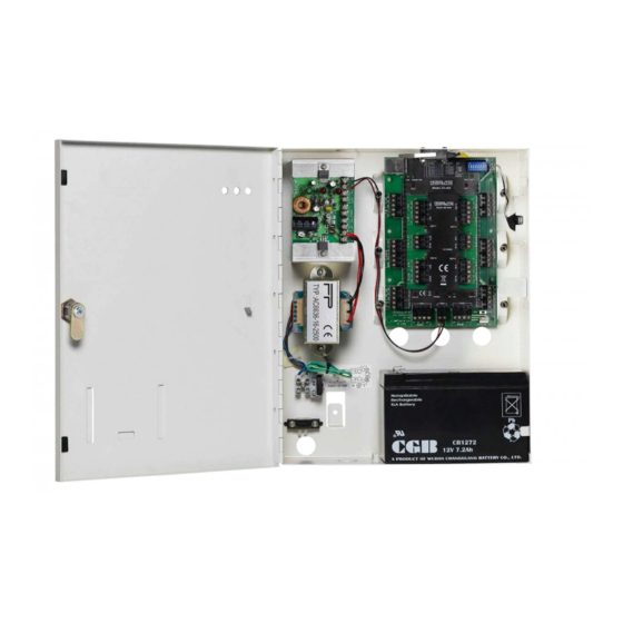
When used in combination with Rosslare's VeriTrax software system, the AC-225 gives you full control over access to your premises. The system can control both single and double door entrances, supports up to 30,000 users and uses flash memory to enable easy firmware upgrades. - Page 5 Introduction Figure 1 AC-225 panel AC-225 Hardware Installation and User Guide Page 4...
-
Page 6: Features
Introduction 1.1 Features The AC-225 is a powerful and adaptable access control solution with a range of powerful features. • Controls 1 or 2 doors (DIP switch controlled) • Two IN/OUT readers, with tamper switch and LED control • Four inputs, selectable as supervised or non-supervised •... - Page 7 Fingerprint Recognition VeriTrax can share user details with Rosslare's BioTraxNet software system. The BioTraxNet system can then download all selected users information to an AYC-W6500 fingerprint reader. AC-225 Hardware Installation and User Guide...
-
Page 8: Technical Specifications
Technical Specifications Technical Specifications Electrical Characteristics Operating Voltage 12V DC 0.5A from PS-14 Maximum Input Current AC-225: Standby: 80mA Maximum: 325mA AC-225IP: Standby: 120mA Maximum: 370mA General Inputs 4 supervised high impedance inputs. (12 supervised inputs when used with the optional MD-IO84 I/O expansion board) Maximum voltage: 5V DC Relay Outputs... - Page 9 Technical Specifications Communication Characteristics RS-232 Terminal Block RS-485 Molex and Terminal Block TCP/IP On-board RJ-45 connector (AC-225IP only) Speed Options 9600 bps 19200 bps 57600 bps 115200 bps Reader 2 reader ports Output voltage Environmental Characteristics Operating Temperature 32°F - 120°F (0°C - 49°C) Range Operating Humidity 0 - 90% (Non-condensing)
- Page 10 Technical Specifications Power Supply Specifications Input Voltage 16V AC / 2.5A From Transformer - 13.8V/300mA Output Voltage 1 From Transformer - 12VDC Lead Acid battery up to Backup Battery Charger 7A/H From Transformer - 12V DC / 0.5A Output Voltage 2 Access control panel - 12V DC / 1.5A Output Voltage 3...
-
Page 11: Ac-225 Panel Set-Up
AC-225 Panel Set-Up AC-225 Panel Set-Up Every AC-225 panel controls one or two doors. The panels connect together in a network and are controlled by a central server computer, running the AS-225 VeriTrax software system. The following diagram shows an example set-up for a network of AC-225 access control panels. -
Page 12: Inputs Wiring - Non-Supervised Inputs
AC-225 Panel Set-Up 3.1 Inputs Wiring – Non-Supervised Inputs Figure 3: Inputs Wiring – Non-supervised Inputs 3.2 Inputs Wiring – Supervised Inputs When wiring the AC-225 for supervised inputs, resistors should be placed on the input switch and not on the terminal block. For further details refer to Input and Output Requirements on page 16. -
Page 13: Outputs Wiring
AC-225 Panel Set-Up 3.3 Outputs Wiring The following diagram illustrates wiring for two main types of 12VDC electrical release mechanisms. Other electrical devices can be switched using the voltage free relay contacts. Figure 4: Door Lock – Failed Close Figure 5: Door Lock – Failed Open AC-225 Hardware Installation and User Guide Page 12... -
Page 14: Power Supply
AC-225 Panel Set-Up 3.4 Power Supply The following diagram illustrates wiring between the PS-14 power supply and the AC-225. It is recommended to add a 12VDC lead acid backup battery if the main power supply fails. If the main output is 12VDC, wire it to the PS-14. Otherwise support your power supply according to the output requirements. - Page 15 AC-225 Panel Set-Up Figure 6: Wiring Between PS-14 and AC-225 AC-225 Hardware Installation and User Guide Page 14...
-
Page 16: Reader
AC-225 Panel Set-Up 3.5 Reader Proximity & keypad readers are supplied with a limited cable. The color of the cable cover represents the cable’s function. Note: When extending the cable distance, be careful with the color of the cable cover. Refer to the reader specifications for the maximum cable length (typically 150m with an 18 AWG cable). -
Page 17: Input And Output Requirements
Input and Output Requirements Input and Output Requirements This chapter describes the AC-225 access control panel's input and output requirements. 4.1 Input Types There are four input types – Normally Open, Normally Closed, Normally Open Supervised 1 or 2 resistors, and Normally Closed Supervised 1 or 2 resistors. - Page 18 Input and Output Requirements Normally Open Input Connection: Normally Open Input has 2 states: • Switch Open - Normal State: Loop resistance = Infinite (open circuit). • Switch Closed – Abnormal State: Loop resistance = 0 (short circuit). Figure 8: Normally Open Input Connection Page 17 AC-225 Hardware Installation and User Guide...
- Page 19 Input and Output Requirements Normally Closed Input Connection: Normally Closed Input has two states: • Switch Closed - Normal State: Loop resistance = 0 (short circuit). • Switch Open – Abnormal State: Loop resistance = Infinite (open circuit). Figure 9: Normally Closed Input Connection AC-225 Hardware Installation and User Guide Page 18...
- Page 20 Input and Output Requirements Normally Open Supervised Single Resistor Input Connection Connect an 8.2K resistor in parallel to the input switch contacts. Normally Open Supervised Input has 3 states: • Switch Open - Normal State: Loop resistance = 8.2K. • Switch Closed – Abnormal State: Loop resistance = 0 (short circuit).
- Page 21 Input and Output Requirements Normally Open Supervised Double Resistor Input Connection Connect a 2.2K resistor in series to the input switch contacts. Connect an 8.2K resistor parallel to the input switch contacts. Normally Open Supervised Input has 3 states: 1) Switch Open - Normal State: Loop resistance = 10.4K.
- Page 22 Input and Output Requirements Normally Closed Supervised Single Resistor Input Connection Connect a 2.2K resistor in series to the input switch contacts. Normally Closed Supervised Input has 3 states: • Switch Closed - Normal State: Loop resistance = 2.2K. • Switch Open – Abnormal State: Loop resistance = Infinite (open circuit).
-
Page 23: Inputs Description
Input and Output Requirements • Open circuit (Infinite loop resistance) or short circuit (0 resistance) across input terminals - Trouble State. Figure 13: Normally Closed Supervised Input (Double Resistor) 4.2 Inputs Description Request to Exit Button (REX) Input Use the REX Input to open a door directly. The following should be defined: Single door controller: Door 1 –... - Page 24 Input and Output Requirements Door Monitor Input The Door Monitor Input typically connects to a Normally Closed door sensing micro-switch for door status monitoring. The following should be defined: Single door controller: Door 1 - IN1A Double door controller: Door 1 - IN 1A Door 2 - IN 2A The panel can generate two warning conditions: •...
-
Page 25: Outputs
Refer to the UL Listed burglary unit for connection instructions. 4.3 Outputs Rosslare Security recommends the use of suppression diodes for all outputs that will be connected to inductive loads and activated by DC current, such as Magnetic Lock ("Maglock") or door strike devices. -
Page 26: Card Readers And Keypads
Input and Output Requirements Note: The user can select either "Normally Open" or "Normally Closed" output contacts. The following should be defined: Single door controller: Door 1 – OUT1 Double door controller: Door 1 – OUT1 Door 2 – OUT2 The output can sink current from any power supply (see page 13). - Page 27 Input and Output Requirements Single door controller: Door 1 – Reader 1 IN/OUT Door 1 – Reader 2 IN/OUT Double door controller: Door 1 – Reader 1 IN/OUT Door 2 – Reader 2 IN/OUT Use the VeriTrax AS-225 software to set the readers for IN or OUT use and to set the data transmission format for each reader.
-
Page 28: Ac-225 Hardware Settings
AC-225 Hardware Settings AC-225 Hardware Settings Each AC-225 panel controls an entrance. The behavior of the panel is controlled by DIP switch settings. Select the appropriate DIP switch setting to operate the panel as either a single or double door. See below Access Control Panel Type, page 29. -
Page 29: Dip Switch Configuration
AC-225 Hardware Settings 5.1 DIP Switch Configuration The access control panel DIP switch controls a number of operating parameters including the device address and baud rates for serial communication. 1 2 3 4 5 6 7 8 Figure 14: DIP Switch The following is a list of DIP switch numbers and their functions: Function Switch... -
Page 30: Access Control Panel Type
AC-225 Hardware Settings 1 2 3 4 5 6 7 8 Figure 15: DIP Switch with Baud Rate Setting The following lists switch 1 and 2 status and baud rate: Switch 1 Switch 2 Baud Rate 9600 19200 115200 57600 Note: The access control panel baud rate must be identical to the host computer's serial port baud rate. -
Page 31: Access Control Panel Addressing
AC-225 Hardware Settings Single Door Controller This access type has two readers, IN and OUT, as follows: Outputs Door lock strike General purpose output General purpose output General purpose output Inputs Release to exit Door monitor input General purpose input General purpose input Note: For more information, refer to Input and Output... - Page 32 AC-225 Hardware Settings 1 2 3 4 5 6 7 8 Figure 17: DIP Switch with Internal Network Address Setting Note: For successful communications, the DIP switch must match the address set in the VeriTrax AS-225 software. The following table displays the 32 dip switch settings available: Address Switch 4 Switch 5 Switch 6 Switch 7 Switch 8 Page 31...
- Page 33 AC-225 Hardware Settings AC-225 Hardware Installation and User Guide Page 32...
-
Page 34: Communications
Communications Communications Communication lines are used to upload and download information between the access control panel and the VeriTrax AS-225 software. When the access control panel and the computer are communicating, the system’s two LEDs flash accordingly. • The RX LED flashes when the controller receives data •... - Page 35 Communications RS-232 Connection to the Computer Set the J1 switch to the RS-232 position. Access DB25 Connector control panel Connector Pin 5 Pin 7 Pin 2 Pin 3 Pin 3 Pin 2 Note: The RS-232 connection can only connect a single access control panel to the computer.
- Page 36 Communications Daisy Chaining Daisy chaining allows many panels to connect to the computer along a single serial line. The first panel is connected directly to the computer and a second panel connects to the first panel. Additional panels connect in the same way, one after another. AC-225 #1 RS-485 AC-225 #2...
-
Page 37: Tcp/Ip Network Connection
TCP/IP network, This means that one AC-225IP panel can support up to 31 AC-225 panels. To connect to a TCP/IP network using other AC-225 models, add Rosslare's MD-N32 TCP/IP to RS-232 gateway converter. Note: For more information on operating an MD-N32, refer to the MD-N32 User Manual. - Page 38 Figure 19: MD-N32 Configuration connecting a single panel When using an MD-N32, for a single panel, either an RS-232 cable or Rosslare's MD-14 RS-485 converter can be used. To connect an MD-N32 to more than one panel (up to 32 panels), Rosslare's MD-14 RS-485 converter must be used.
-
Page 39: Modem Network Connection
• 2 Standard Telephone cables – RJ11 plugs in both sides • Crossed 9 pin RS-232 cable (female jack on both sides) • Rosslare MD-14 (RS-232 to RS-485 converter) • 2 Rosslare MD-N33 (Modem to serial gateway) • Rosslare AC-225 panel AC-225 Hardware Installation and User Guide... - Page 40 Communications Prerequisites Before performing permanent modem installations, the modem that will be connected to the panel must be initialized from the computer running the VeriTrax software. Note: The telephone numbers shown in the examples below are for illustration purposes only. Computer Connections The MD-N33 must connect to the computer via a serial port.
-
Page 41: Appendix A. Limited Warranty
(24 Months). Warranty Remedy Coverage In the event of a breach of warranty, ROSSLARE will credit Customer with the price of the Product paid by Customer, provided that the warranty claim is delivered to ROSSLARE by the Customer during the warranty period in accordance with the terms of this warranty. - Page 42 This warranty shall not extend to any ancillary equipment not furnished by ROSSLARE, which is attached to or used in conjunction with a Product, nor to any Product that is used with any ancillary equipment, which is not furnished by ROSSLARE.
-
Page 43: Appendix B. Technical Support
Technical Support Appendix B. Technical Support Asia Pacific, Middle East, Africa Rosslare Security Products Headquarters 905-912 Wing Fat Industrial Bldg, 12 Wang Tai Road, Kowloon Bay Hong Kong Tel: +852 2795-5630 Fax: +852 2795-1508 E-mail: support.apac@rosslaresecurity.com United States and Canada... - Page 45 www.rosslaresecurity.com...
Need help?
Do you have a question about the AC-225? AC-225IP? AC-225U and is the answer not in the manual?
Questions and answers