Table of Contents
Advertisement
Advertisement
Table of Contents

Related Manuals for Rosslare AC-825IP


Summary of Contents for Rosslare AC-825IP
- Page 1 AC-825IP Networked Controller Hardware Installation and User Guide...
- Page 2 ROSSLARE. ROSSLARE reserves the right to revise and change this document at any time, without being obliged to announce such revisions or changes beforehand or after the fact.
-
Page 3: Table Of Contents
Compatible Readers ................10 2. Technical Specifications ..........11 ME-1515 Enclosure ................11 Expansions for AC-825IP ..............12 3. AC-825IP Panel Setup ............13 Mounting ..................14 3.1.1 Mounting the ME-1515 Enclosure .............. 14 Connecting the Pull-Safe™ Cable Locks ............16 3.1.2... - Page 4 Door Lock ....................36 Card Readers and Keypads ..............37 5. AC-825IP Hardware Settings .......... 39 DIP Switch Configuration ..............42 Setting AC-825IP Panel Type in AxTraxNG ......... 42 6. Communications ............. 43 TCP/IP Network Connection .............. 43 6.1.1 LAN and WAN Requirements ..............43 A.
- Page 5 Figure 26: Normally Open Supervised Input (Double Resistor) ......33 Figure 27: Normally Closed Supervised Input (Single Resistor) ......33 Figure 28: Normally Closed Supervised Input (Double Resistor) ...... 34 Figure 29: Connecting Multiple AC-825IP Panels to the AxTraxNG Server..43 AC-825IP Hardware Installation and User Guide...
- Page 6 List of Tables List of Tables Table 1: Serial Address and DIP Switch Combinations ........27 Table 2: Possible Hardware Settings .............. 39 AC-825IP Hardware Installation and User Guide...
- Page 7 ROSSLARE ENTERPRISES LIMITED and/or its related companies and/or subsidiaries’ (hereafter: "Rosslare") exclusive warranty and liability is limited to the warranty and liability statement provided in an appendix at the end of this document.
-
Page 8: Introduction
100,000 users and 500,000 events. Each AC-825IP access control unit (ACU) supports up to 6 doors (In/Out), each with 2 inputs and 1 output, and includes four additional auxiliary inputs and two auxiliary outputs. -
Page 9: Open Supervised Device Protocol
Each panel can connect to up to two readers via OSDP. Any device that is connected to the AC-825IP panel via RS-485 must have a unique serial address. AxTraxNG The AxTraxNG software is custom designed to set up, manage, and supervise all aspects of an access controller’s network. -
Page 10: Configurable Links
Compatible Readers The AC-825IP ACU provides support for most of the Wiegand formats, such as 26-bit, 30-bit, 32-bit, 35-bit, and 36-bit, as well as any OSDP readers that may be connected serially to the AC-825IP via RS-485 interface. -
Page 11: Technical Specifications
(per reader, between readers) Security Modes Normal and Secure ENVIRONMENTAL SPECIFICATIONS Operating Temp. Range -5°C to 50°C (23°F to 122°F) Storage Temp. Range -25°C to 50°C (-13°F to 122°F) Operating Humidity Range 0 to 85% (non-condensing) AC-825IP Hardware Installation and User Guide... -
Page 12: Expansions For Ac-825Ip
Range MECHANICAL SPECIFICATIONS Weight 150 g 230 g 200 g (8.1 oz) (7.1 oz) (5.3 oz) Dimensions (H x W x D) 178 x 87 x 30 mm (7.0 x 3.4 x 1.2 in.) AC-825IP Hardware Installation and User Guide... -
Page 13: Ac-825Ip Panel Setup
The unit should only be installed by a professional service person. Each AC-825IP panel controls 6 or 10 doors (with the D-805) (3 or 5 doors in double reader per door mode). The panels connect together in a network and are controlled by a central server computer, running the AxTraxNG software system. -
Page 14: Mounting
Bushings are needed for any conductors leaving the enclosure through the provided openings. Mounting The AC-825IP control panel either comes pre-mounted within the ME-1515 enclosure, which then needs to be wall mounted, or you can mount the control panel directly onto a wall using the DIN rail enclosure. -
Page 15: Figure 3: C14 Socket
Optionally, you can add Pull-Safe™ cable locks to secure the C13 power cord (see Section 3.1.2). The maximum power rating and input allowed is indicated on the cover of the AC terminal inside the enclosure (Figure 4). Figure 4: Location of the Maximum Power Rating Sticker AC-825IP Hardware Installation and User Guide... -
Page 16: Connecting The Pull-Safe™ Cable Locks
(Figure 5). Figure 5: Attaching the Pull-Safe Cable Locks Insert the screws into their designated areas and screw them in tightly. Pull on the cord to check that the cord is secured. AC-825IP Hardware Installation and User Guide... -
Page 17: Mounting Using The Din Rail
AC-825IP Panel Setup 3.1.3 Mounting using the DIN Rail The AC-825IP control panel and its extensions can also be installed directly on a wall (without the ME-1515 enclosure) using a DIN rail and the accompanying casing for the AC-825IP panel or extension(s). -
Page 18: Figure 8: Positioning The Panels
Add a kind of stopper or screw underneath each unit so the unit does not slide down the DIN rail. Figure 9: Adding a Screw as a Stopper If you have multiple units along a DIN rail, we suggest having a 2-cm gap between each unit. AC-825IP Hardware Installation and User Guide... -
Page 19: Figure 10: Din Rail Dimensions (Top View)
EN 50022 standard with the following dimensions as shown in Figure 10. Figure 10: DIN Rail Dimensions (Top View) Each unit needs to be connected to a power supply. For further information, please refer to the electrical specifications (Chapter 2). AC-825IP Hardware Installation and User Guide... -
Page 20: Input Wiring - Supervised Inputs
AC-825IP Panel Setup Input Wiring – Supervised Inputs When wiring the AC-825IP for supervised inputs, resistors should be placed on the input switch and not on the terminal block. Figure 11 presents a view of the inputs and their connection options. -
Page 21: Output Wiring
Figure 12 and Figure 13 illustrate wiring for two main types of 12 VDC electrical release mechanisms. Other electrical devices can be switched using the voltage free relay contacts. Figure 12: Door Lock – Failed Close AC-825IP Hardware Installation and User Guide... -
Page 22: Figure 13: Door Lock - Failed Open
AC-825IP Panel Setup Figure 13: Door Lock – Failed Open AC-825IP Hardware Installation and User Guide... -
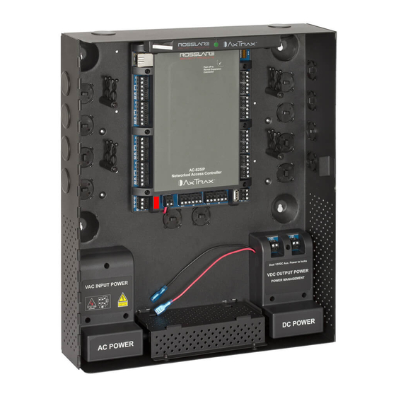
Page 23: Power Management
AC-825IP Panel Setup Power Management Figure 14 illustrates the AC-825IP ACU within the ME-1515 enclosure. It is recommended to add a 12 VDC lead acid backup battery in case the power management board fails (see Chapter 2). If the main input is 12 VDC, wire it to the power management board, which has a load rating of up to 4 A for lock connectivity (for battery installation instructions, please refer to Section 3.1). -
Page 24: Ac-825Ip Wiring Ports
Figure 15: AC-825IP Wiring Communications AUX1 and AUX 2 are additional auxiliary inputs and auxiliary outputs. Refer to Chapter 2 for maximum power ratings and further information. The USB G-bus ports and DIP switches are currently not functional. AC-825IP Hardware Installation and User Guide... -
Page 25: R/S/D/P-805 Extension Board Setup
(Figure 16). Figure 16: Slot for Expansion Board Attachment When adding an expansion board to the expansion slot of the AC-825IP panel, make sure the power to the control panel is off. The system can support up to 12 expansion boards via OSDP. -
Page 26: Daisy Chain System
AC-825IP Panel Setup 3.6.1 Daisy Chain System Figure 17 shows an example daisy chain setup for a network of one AC-825IP access control panel plus 6 expansion boards using four ME-1515 enclosures. Figure 17: Daisy Chain Setup The first expansion board is connected to the AC-825IP panel using the OSDP/RSDP bus (serial bus) at the bottom left of the panel (Figure 18). -
Page 27: Dip Switching
16 combinations. However, an AC-825IP panel supports up to 11 unique serial addresses (readers) per panel, so only a maximum of 11 of the 16 serial addresses can be used at any given time. - Page 28 AC-825IP Panel Setup Serial Address DIP Switch Setting Rosslare readers that support OSDP operation are compatible with most OSDP commands. The reader address is set using DIP switches on the back of the reader. AC-825IP Hardware Installation and User Guide...
-
Page 29: Readers And Cable Length
Readers are supplied with cables having a limited length. The color of the cable cover represents the cable’s functionality according to the Wiegand and OSDP standards (Figure 21 and Figure 22). Figure 21: Reader Wiring – Wiegand Figure 22: Reader Wiring – OSDP AC-825IP Hardware Installation and User Guide... - Page 30 OSDP readers MUST be set to addresses 13 and 14. Refer to the reader specifications for the maximum cable length, typically 150 m (492 ft) with an 18 AWG cable. AC-825IP Hardware Installation and User Guide...
-
Page 31: Input And Output Connections
Input and Output Connections Input and Output Connections This chapter describes the AC-825IP access control panel's input and output connections. Input Types There are four input types: Normally Closed (N.C.) Normally Open (N.O.) Single EOL resistor ... -
Page 32: Normally Open Supervised Single Eol Resistor Input Connection
Switch Open – Normal State: Loop resistance = 10.4 kΩ Switch Closed – Abnormal State: Loop resistance = 2.2 kΩ Open circuit (infinite loop resistance) or short circuit (0 resistance) across input terminals – Trouble State AC-825IP Hardware Installation and User Guide... -
Page 33: Normally Closed Supervised Single Eol Resistor Input Connection
Switch Closed – Normal State: Loop resistance = 2.2K Switch Open – Abnormal State: Loop resistance = 10.4 kΩ Open circuit (infinite loop resistance) or short circuit (0 resistance) across input terminals – Trouble State AC-825IP Hardware Installation and User Guide... -
Page 34: Inputs Description
The Door Monitor Input typically connects to a Normally Closed door sensing micro-switch for door status monitoring. Using Door Monitor enables many advanced options such as door forced alarm, door held open warnings, interlocking doors and more. AC-825IP Hardware Installation and User Guide... -
Page 35: General Purpose Inputs
General purpose inputs functions when using S-805 or D-805: Unit Expansions S-805 IN 1S to IN 16S P-805 IN 1P to IN 16P D-805 IN 2C IN 2D IN 4C IN 4D AC-825IP Hardware Installation and User Guide... -
Page 36: Outputs
Input and Output Connections Outputs Rosslare Security recommends the use of suppression diodes for all outputs that activate an inductive load. 4.3.1 Door Lock There are two types of door locking devices: Fail open (fail secure) Fail close (fail safe) -
Page 37: Card Readers And Keypads
One Readers per Door Door 1 – Reader 1 IN/OUT Door 2 – Reader 2 IN/OUT Door 3 – Reader 3 IN/OUT Door 4 – Reader 4 IN/OUT Door 5 – Reader 5 (OSDP) IN/OUT Door 6 – Reader 6 (OSDP) IN/OUT AC-825IP Hardware Installation and User Guide... - Page 38 The reader’s tamper output connects to the access control panel's Reader- Tamper input. If the reader is interfered with, an trouble signal can be generated. The controller activates the LED control for the time the door is open. AC-825IP Hardware Installation and User Guide...
-
Page 39: Ac-825Ip Hardware Settings
Door Exit or Entry One Reader per Door: Outputs Door1 Lock output (OUT 1) Door2 Lock output (OUT 2) Door3 Lock output (OUT 3) Door4 Lock output (OUT 4) Door5 Lock output (OUT 5) AC-825IP Hardware Installation and User Guide... - Page 40 Door3 Request-to-Exit (IN 5A) Door3 monitor input (IN 5B) Door4 Request-to-Exit (IN 1C) Door4 monitor input (IN 1D) Door5 Request-to-Exit (IN3C) Door5 monitor input (IN3D) Readers Reader1 (Door1 IN/OUT) Reader2 (Door1 OUT/IN) Reader3 (Door2 IN/OUT) AC-825IP Hardware Installation and User Guide...
- Page 41 (Door2 OUT /IN) Reader3 (Door3 IN/OUT) Reader4 (Door4 OUT /IN) Reader5 (OSDP) (Door5 IN/OUT) Reader6 (OSDP) (Door6 OUT /IN) Reader1D (Door7 IN/OUT) Reader2D (Door8 OUT /IN) Reader3D (Door9 OUT /IN) Reader4D (Door10 OUT /IN) AC-825IP Hardware Installation and User Guide...
-
Page 42: Dip Switch Configuration
Currently not used. Setting AC-825IP Panel Type in AxTraxNG The AC-825IP panel type is defined using AxTraxNG. There are two panel types: a panel with one reader per each door or a panel with two readers per each door. Please refer to the AxTraxNG manual for further details. -
Page 43: Communications
The devices can be connected to an IP network using any valid network address. Figure 29 illustrates the connection of a single AC-825IP to a computer via a LAN network. Figure 29: Connecting Multiple AC-825IP Panels to the AxTraxNG Server The maximum distance from the Ethernet port of the panel to the LAN connection is 99.97 m (328 ft). -
Page 44: Limited Warranty
The full ROSSLARE Limited Warranty Statement is available in the Quick Links section on the ROSSLARE website at www.rosslaresecurity.com. Rosslare considers any use of this product as agreement to the Warranty Terms even if you do not review them. AC-825IP Hardware Installation and User Guide... - Page 45 Tel: +86-755-8610-6842 Rosslare Security Products, Inc. Fax: +86-755-8610-6101 Southlake, TX, USA support.cn@rosslaresecurity.com Toll Free: +1-866-632-1101 Local: +1-817-305-0006 India Fax: +1-817-305-0069 Rosslare Electronics India Pvt Ltd. support.na@rosslaresecurity.com Tel/Fax: +91-20-40147830 Europe Mobile: +91-9975768824 sales.in@rosslaresecurity.com Rosslare Israel Ltd. Rosh HaAyin, Israel Tel: +972-3-938-6838 Fax: +972-3-938-6830 support.eu@rosslaresecurity.com...
Need help?
Do you have a question about the AC-825IP and is the answer not in the manual?
Questions and answers