Rosslare AC-Q41HB Installation And Programming Manual
Anti-vandal standalone controllers
Hide thumbs
Also See for AC-Q41HB:
- Instruction manual (58 pages) ,
- Installation and programming manual (57 pages)

Related Manuals for Rosslare AC-Q41HB


Summary of Contents for Rosslare AC-Q41HB
- Page 1 AC-Q4x Series Anti-Vandal Standalone Controllers Installation and Programming Manual Models: AC-Q41HB AC-Q41HP AC-Q41SB AC-Q42HB AC-Q42HP AC-Q42SB...
- Page 2 ROSSLARE. ROSSLARE reserves the right to revise and change this document at any time, without being obliged to announce such revisions or changes beforehand or after the fact.
-
Page 3: Table Of Contents
Table of Contents Table of Contents Introduction ..............9 Controller Types ..............9 Box Content ................. 10 Ancillary Equipment .............. 10 Front Panel Description ............11 Technical Specifications ..........12 Installation ..............14 Mounting ................14 Wiring .................. 15 3.2.1 Pre-wired Models ................ - Page 4 Table of Contents Tamper Feature ..............28 Lockout Feature (Keypad/Card Tamper) ........28 BL-D40 External Sounder ............29 Programming ............30 Entering the Programming Mode ........... 31 Exiting the Programming Mode ..........32 Changing the Open Code ............32 Changing the Auxiliary Code ..........33 Changing the Programming Code ..........
- Page 5 Table of Contents 5.13.1 Primary Codes Definition .............. 45 5.13.2 Secondary Codes Definition ............46 5.13.3 Enrolling Methods ................ 46 5.14 Deleting Primary and Secondary Codes ........49 5.14.1 Deleting Primary and Secondary Codes using the Standard Method ..................... 49 5.14.2 Deleting Primary and Secondary Codes using the Code Search Method ..................
- Page 6 List of Figures List of Figures Figure 1: Front Panel..................11 Figure 2: Drilling Holes Identification ............... 14 Figure 3: Pre-Wired Connection for Lock Strike Relay & REX......17 Figure 4: Pre-Wired Connection for Auxiliary Input & Output ......18 Figure 5: Pre-Wired Connection for the BL-D40 External Sounder ....
- Page 7 List of Tables List of Tables Table 1: Wire Color Guide ................16 Table 2: Programming Menus................30 Table 3: Quick Reference Guide for Auxiliary Mode Setting ......38 AC-Q4x Series Installation and Programming Manual...
- Page 8 ROSSLARE exclusive warranty and liability is limited to the warranty and liability statement provided in an appendix at the end of this document. ...
-
Page 9: Introduction
Type 41 – PIN only Type 42 – PIN and proximity card Type 44 – PIN and proximity card, with piezoelectric contacts Heater Relay Backlight Keypad Proximity Current Type AC-Q41HB Standard AC-Q41HP Standard AC-Q41SB ... -
Page 10: Box Content
Introduction Box Content Before beginning, verify that all of the following is in the box. If anything is missing please report the discrepancy to your nearest Rosslare Office. One controller unit Installation kit 1 drilling template (label/sticker) ... -
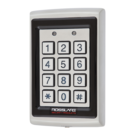
Page 11: Front Panel Description
Introduction Front Panel Description Controls and indicators of all controller versions are identical (excluding the antenna, which is unique to Q42 and Q44) (Figure 1). Figure 1: Front Panel AC-Q4x Series Installation and Programming Manual... -
Page 12: Technical Specifications
Technical Specifications Technical Specifications AC-Q41HB AC-Q42HB AC-Q44 Q41SB Q41HP Q42SB Q42HP Input 12–24 VDC Voltage 12–24 VAC 16–24 VAC 12–24 VAC 16–24 VAC Maximum Heater 130 mA 125 mA 145 mA 130 mA 145 mA 125 mA Input Current Heater... - Page 13 (4.7 x 3.0 x 1.1 in.) Weight 440 g (1.0 lb) 521 g (1.2 lb) * Measured using a Rosslare proximity card or equivalent. Range also depends on electrical environment and proximity to metal. AC-Q4x Series Installation and Programming Manual...
-
Page 14: Installation
Installation Installation Installation of an RFID reader adjacent to metallic surfaces might alter the reader’s specifications. To diminish this interference, use a plastic spacer when mounting the reader. Mounting Prior to starting, select the location where the controller unit is to be mounted. -
Page 15: Wiring
A Torx security screw tool is provided to tighten the security Torx screw. Wiring The controllers are provided either with a pre-wired cable or with a screw-type terminal block: Pre-wired Cabling Models Terminal Block Models AC-Q41SB AC-Q41HB/HP AC-Q42SB AC-Q42HB AC-Q44 AC-Q4x Series Installation and Programming Manual... -
Page 16: Pre-Wired Models
Installation 3.2.1 Pre-wired Models These units are supplied with a 10-conductor 60-cm (24-in.) pigtail (24-AWG cable) with exposed wires coated with solder. To wire the controller: 1. Select the appropriate connections according to Table 1. Table 1: Wire Color Guide Color Description V input... -
Page 17: Figure 3: Pre-Wired Connection For Lock Strike Relay & Rex
Installation Figure 3: Pre-Wired Connection for Lock Strike Relay & REX AC-Q4x Series Installation and Programming Manual... -
Page 18: Figure 4: Pre-Wired Connection For Auxiliary Input & Output
Installation Figure 4: Pre-Wired Connection for Auxiliary Input & Output AC-Q4x Series Installation and Programming Manual... -
Page 19: Figure 5: Pre-Wired Connection For The Bl-D40 External Sounder
Installation Figure 5: Pre-Wired Connection for the BL-D40 External Sounder AC-Q4x Series Installation and Programming Manual... -
Page 20: Terminal Block Models
Installation 3.2.2 Terminal Block Models These controllers come with removable terminal blocks that are pushed on pins on the motherboard of the controllers. To wire the terminal blocks: 1. Route the wires or cable through the large hole in the back cover See Figure 6. -
Page 21: Figure 7: Terminal Block Wiring Of The Lock Strike Relay & Rex
Installation Figure 7: Terminal Block Wiring of the Lock Strike Relay & REX AC-Q4x Series Installation and Programming Manual... -
Page 22: Figure 8: Terminal Block Wiring Of The Auxiliary Input And Output
Installation Figure 8: Terminal Block Wiring of the Auxiliary Input and Output AC-Q4x Series Installation and Programming Manual... -
Page 23: Figure 9: Terminal Block Wiring Of The Bl-D40 External Sounder
Installation Figure 9: Terminal Block Wiring of the BL-D40 External Sounder AC-Q4x Series Installation and Programming Manual... -
Page 24: Operation
Operation Operation • In the Operation chapter, “code” refers to a PIN code or proximity card depending on the unit you have. • Memory slots can be a proximity card or PIN code depending on the unit you have. Modes of Operation The control units have three modes of operation. -
Page 25: User Levels
Operation Fail Secure Operation, the door is locked until the star button (*) is pressed. When the Lock Strike relay is programmed for Fail Safe Operation, the door is constantly unlocked. In case of power failure, once the power is restored, the controller returns to Normal mode for security reasons. -
Page 26: Switching Operational Modes
Operation Switching Operational Modes The three modes of operation defined above can be changed through a few steps. 4.3.1 From Normal to Secure Mode The default factory setting for the normal/secure code is 3838. To change from Normal to Secure mode: 1. -
Page 27: From Normal To Bypass Mode
Operation 4.3.3 From Normal to Bypass Mode By default, there is no Normal/Bypass code. The Normal/Bypass code must first be programmed to use this function (see Section 5.7 to create/modify the Normal/Bypass code). To change from Normal to By pass mode: 1. -
Page 28: Tamper Feature
Operation The function of the REX button depends on the Lock Strike relay, whether it is programmed for failsafe or for fail secure operation. Fail Secure Operation From the moment the REX button is pressed, the door is unlocked until the Lock Strike Release time has elapsed. -
Page 29: Bl-D40 External Sounder
(opened or removed from the wall). The length of the siren can also be programmed in the controller. The controller communicates with the BL-D40 via a Rosslare proprietary protocol. If the BL-D40 receives an unrecognized code over its communication line or communications between the controller and the BL-D40 are severed, the strobe flashes repeatedly, until the communication problem has been resolved. -
Page 30: Programming
Programming Programming • In the Programming chapter, “code” refers to a PIN code or proximity card depending on the unit you have. • When entering a PIN or presenting a proximity card is mentioned, the meaning may vary between units. Programming is done solely via the unit’s keypad-driven Programming Menu System. -
Page 31: Entering The Programming Mode
Programming Menu Description Default Section 4-8 Digits Digits Digits Digits Enroll proximity cards, PIN 5.13 or both Delete proximity cards or 5.14 Code assignment with 5.15 strike/auxiliary Return to factory 5.16 defaults/Change PIN code Length Entering the Programming Mode • The controller must be in Normal mode to enter the programming mode. -
Page 32: Exiting The Programming Mode
Programming Exiting the Programming Mode • Wrong entries may reset the controller back to Normal mode. • If no key is pressed for 1 minute, while in programming mode, the controller exits Programming mode and returns to Normal mode. To ex it Programming mode: 1. -
Page 33: Changing The Auxiliary Code
Programming To change the Open code: 1. Enter Programming mode. Green 2. Press 1 to enter Menu 1. The left LED turns red. Red Green 3. Enter the new 4-digit Open code. You hear three beeps. Green The system returns to Normal mode. Changing the Auxiliary Code The Auxiliary code is mainly used as a method to quickly test the Auxiliary relay during installation. -
Page 34: Changing The Programming Code
Programming 3. Enter the new 4-digit Auxiliary code. You hear three beeps. The system returns to Normal mode. Green Changing the Programming Code • The Programming code cannot be erased; the code 0000 is invalid and does not erase the Programming code. •... -
Page 35: Changing The Normal/Bypass Code
Programming 3. Enter the new 4-digit Normal/Secure code. You hear three beeps. The system returns to Normal mode. Green Changing the Normal/Bypass Code The Normal/Bypass code is also used to turn the door chime off and on. Chime only functions with the BL-D40 external sounder. •... -
Page 36: Setting Fail Safe/Secure Operation, Tamper Siren And Lock Strike Release Time
Programming Setting Fail Safe/Secure Operation, Tamper Siren and Lock Strike Release Time The default value is 0004, which corresponds to Fail Secure operation, no siren, and 4-seconds Lock Strike release time. To set the Fail Safe/ Secure Operation, Tamper Siren and Lock Strike Release Time: 1. -
Page 37: Setting Auxiliary Modes
Programming Setting Auxiliary Modes The default auxiliary setting is 2004. Auxiliary Relay activation is subject to the user’s Auxiliary code assignment (excluding Shunt, which is activated by all users). For more details, see Section 5.15. To set Aux iliary modes: 1. -
Page 38: Table 3: Quick Reference Guide For Auxiliary Mode Setting
Programming Table 3: Quick Reference Guide for Auxiliary Mode Setting Auxiliary Auxiliary Auxiliary Output Auxiliary Auxiliary Settings Mode Input Activated by Relay (in seconds) Function AUX REX Valid code or AUX N.O. 01 to 99 Aux. Relay Release Time 00 Aux. relay toggle Normal/Secure Valid code N.O. -
Page 39: Auxiliary Mode 0
Programming The following subsections describe each Auxiliary mode. 5.9.1 Auxiliary Mode 0 Auxiliary input function: Activates the auxiliary output Auxiliary output activated by: Valid user code, Auxiliary code, Auxiliary input For example, in Auxiliary Mode 0, the controller can function as a 2-door controller. -
Page 40: Auxiliary Mode 3
Programming switch timer or alarm system output to the auxiliary input, the controller can be automatically switched from Normal mode (during office hours) to Secure mode (after office hours). 5.9.4 Auxiliary Mode 3 Auxiliary input function: Toggles Normal/Secure modes Auxiliary output activated by: Alarms For example, in Auxiliary Mode 3, the auxiliary output is activated if the controller is tampered;... -
Page 41: Auxiliary Mode 6
Programming opens, the auxiliary relay opens; if the door closes, the auxiliary relay closes. When a valid code is entered, a countdown for maximum Shunt time, as defined by the auxiliary setting, begins; if the door is not closed before the maximum Shunt time, the alarm is triggered. 5.9.7 Auxiliary Mode 6 Auxiliary input function: Door Monitor... -
Page 42: Auxiliary Mode 8
Programming 5.9.9 Auxiliary Mode 8 Auxiliary input function: Green LED control Auxiliary output activated by: Valid user code, Auxiliary code For example, in Auxiliary Mode 8, the controller can function as a 2-door controller and also provide indicator functionality control. The auxiliary relay is connected to the lock on the second door. -
Page 43: Keypad Heater Operation
Programming 5.10 Keypad Heater Operation This section is not applicable for AC-Q44 (without keypad heater). The controllers contain a built-in keypad heater. Once the heater circuitry is activated, the heater turns on when the ambient temperature drops to 4±1°C and remains on until the keypad temperature rises to 7(+2 or -1)°C. - Page 44 Programming controller beeps every two seconds. The default setting for the Lockout Feature is 4000 (Lockout Disabled). Using the lockout feature is highly recommended, especially when selecting to use short PIN code length (4 or 5 digits). To define the Lockout feature: Mode Door 1.
-
Page 45: Setting The Backlight Behavior
Programming 5.12 Setting the Backlight Behavior This section is applicable for AC-Q4xHB/SB models only (backlight). The controller allows you to define the way the unit’s backlight works. To set the backlight behavior: 1. Enter Programming mode. Press 6 to enter Menu 6. The left LED flashes green. -
Page 46: Secondary Codes Definition
Programming 5.13.2 Secondary Codes Definition Secondary codes can only be enrolled to a user slot that already includes a primary code. A secondary code need not be unique; for instance, one user’s Secondary code may be the same as that of another user. ... - Page 47 Programming 3. Enter the 3-digit user slot number between 001and 500 for the slot to which you wish to enroll a Primary or Secondary code. For example, User Slot 003 represents User #3. If the selected slot has no Primary code, the left LED flashes green, indicating that the Gree Orange controller is ready to accept a Primary code.
- Page 48 Programming 5.13.3.2 Enrolling Secondary Codes using the Code Search Method The code search method enables to quickly enroll a secondary code for a user whose primary code is known and whose slot number is unknown. To enroll secondary codes using the Code Search method: 1.
-
Page 49: Deleting Primary And Secondary Codes
Programming 5. Perform one of the following: Enter the PIN code to be used as the Secondary code. Present the user card to be used as the Secondary code. If the Secondary code is valid, the controller beeps three times and returns to Normal mode. -
Page 50: Deleting Primary And Secondary Codes Using The Code Search Method
Programming The left LED flashes red indicating the controller is waiting for the Programming code Red Orange to confirm the deletion. If the user slot is empty, you hear a long beep and the unit returns to Normal mode. 4. Enter your 4-digit Programming code to confirm the deletion. -
Page 51: Relay Codes Assignment
Programming 4. Perform one of the following: Enter the PIN code of the Primary code belonging to the user you want to delete. Present the user card of the Primary code belonging to the user you want to delete. The left LED flashes red. -
Page 52: Relay Code Assignment Using Search Method
Programming The left LED flashes green. Green Orange 4. Enter the assignment digit for the current user slot: 1 activates the Lock Strike relay only default 2 activates the Auxiliary relay only 3 activates the Lock Strike and Auxiliary relays ... - Page 53 Programming 4. Do one of the following: Enter the PIN code of the Primary code belonging to the user you want to delete. Present the user card of the Primary code belonging to the user you want to delete. The left LED flashes green.
-
Page 54: Changing Pin Code Length/Factory Default Settings
Programming 5.16 Changing PIN Code Length/Factory Default Settings You must be very careful before using this command! Changing the PIN code length also erases the entire memory contents, including all user and special codes, and returns all codes to their factory default settings. To change PIN code length: 1. -
Page 55: Replacing A Programming Code
Programming 5.17 Replacing a Programming Code The controller must be in Normal mode for the procedure to work. Ensure that the Mode indicator is green before proceeding. To replace a Programming code: 1. Remove power from the controller. 2. Press and hold the REX button. 3. -
Page 56: Limited Warranty
The full ROSSLARE Limited Warranty Statement is available in the Quick Links section on the ROSSLARE website at www.rosslaresecurity.com. Rosslare considers any use of this product as agreement to the Warranty Terms even if you do not review them. This device complies with part 15 of the FCC Rules. - Page 57 +86 755 8610 6842 Fax: +86 755 8610 6101 Rosslare Security Products, Inc. support.cn@rosslaresecurity.com Southlake, TX, USA Toll Free: +1-866-632-1101 India Local: +1-817-305-0006 Rosslare Electronics India Pvt Ltd. Fax: +1-817-305-0069 Tel/Fax: +91 20 40147830 support.na@rosslaresecurity.com Mobile: +91 9975768824 Europe sales.in@rosslaresecurity.com Rosslare Israel Ltd.
Need help?
Do you have a question about the AC-Q41HB and is the answer not in the manual?
Questions and answers