
Related Manuals for Rosslare AC-225 PCBA


Summarization of Contents
Introduction
AxTraxNG Software System
Details the capabilities and features of the AxTraxNG access control management software.
Client-Server Structure
Explains the client-server architecture of the AxTraxNG system.
Configurable Links
Describes how to trigger outputs or alarms based on selected inputs.
Fingerprint Recognition Integration
Information on integrating fingerprint readers with the BioTrax system.
Compatible Readers
Lists UL-listed PIN and PROX card readers compatible with the system.
Technical Specifications
Electrical Characteristics
Details operating voltage, maximum input current for AC-225 and AC-225IP.
General Inputs
Information on supervised inputs and expansion boards.
Relay Outputs
Details on the number and type of relay outputs available.
Reader Ports
Specifies the number of reader ports and their voltage/current ratings.
Visual Indicators & Audio
Describes the panel's LEDs and built-in sounder.
Battery Standby Time
Indicates the duration of backup operation with a 12V battery.
Communication Characteristics
Details RS-232, RS-485, and TCP/IP communication interfaces.
Speed Options
Lists the available communication speed options in bits per second.
Environmental Characteristics
Specifies the operating temperature and humidity ranges.
Dimensions and Weight
Provides physical dimensions and weight for AC-225 and AC-225IP models.
AC Transformer Specifications
Details AC transformer requirements for IP models.
PS-33 Power Supply Specifications
Lists input voltage, charger output, and panel/relay output voltages for PS-33.
PS-33 Power Supply Indication
Explains the indication for tamper output and power LEDs on PS-33.
AC-225x Panel Setup
Inputs Wiring – Non-supervised Inputs
Detailed view of non-supervised input connection options on the panel.
Inputs Wiring – Supervised Inputs
Instructions for wiring supervised inputs using resistors.
Outputs Wiring
Illustrates wiring for electrical release mechanisms and relay contacts.
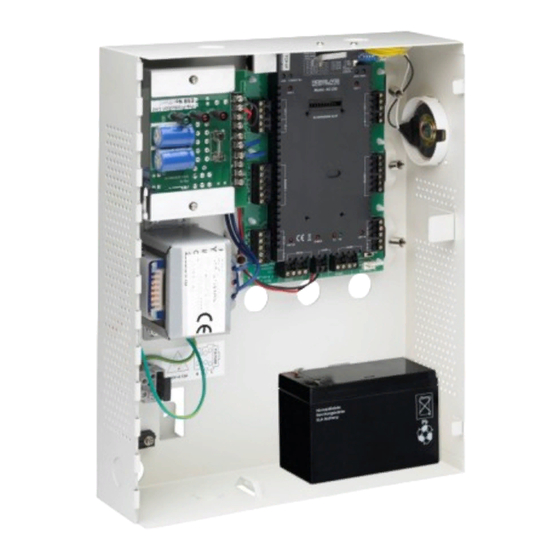
Power Supply Connection
Wiring between PS-33 power supply and AC-225x, including battery backup.
AC-225x Wiring Communications
Detailed view of panel wiring for communications.
Reader Connections
Explains reader wiring and cable function representation.
MD-IO84 Expansion Board
Details the MD-IO84 board for adding relay outputs and supervised inputs.
MD-D02 Expansion Board
Describes the MD-D02 board for adding reader and input/output ports.
Input and Output Connections
Input Types
Describes four input types: NO, NC, NO Supervised, NC Supervised.
Normally Open Input Connection
Explains the two states of a Normally Open input connection.
Normally Closed Input Connection
Details the two states of a Normally Closed input connection.
Normally Open Supervised Single Resistor Input
Wiring for NO supervised input with a single parallel resistor.
Normally Open Supervised Double Resistor Input
Wiring for NO supervised input with series and parallel resistors.
Normally Closed Supervised Single Resistor Input
Wiring for NC supervised input with a single series resistor.
Normally Closed Supervised Double Resistor Input
Wiring for NC supervised input with series and parallel resistors.
Inputs Description
Explains the function and connection of various input types.
Request to Exit (REX) Input
Details the REX input for opening doors without card or PIN entry.
Door Monitor Input
Explains the Door Monitor input for door status and advanced options.
General Purpose Inputs
Describes free inputs for various functions like tampering or alarms.
Outputs
Details door lock outputs and recommendations for inductive loads.
Card Readers and Keypads
Information on connecting card readers and keypads to the panel.
AC-225x Hardware Settings
DIP Switch Configuration
Controls operating parameters like device address and baud rates via DIP switches.
DIP Switch Functions
Lists the functions of DIP switches 1-8 for panel configuration.
Access Control Panel Baud Rate
Sets the serial port baud rate for PC communication via DIP switches.
Access Control Panel Type
Defines panel type (readers per door) using DIP switch 3.
Access Control Panel Addressing
Sets the panel's network address using DIP switches 4-8.
Communications
Serial Network Connection
Connects the panel to a computer using RS-232 or RS-485 serial interfaces.
RS-232 Connection to Computer
Details RS-232 connection, pinouts, and distance limitations.
RS-485 Connection to Computer
Explains RS-485 connection for multiple panels and extended distances.
Daisy Chaining
Describes how to connect multiple panels in a daisy chain configuration.
TCP/IP Network Connection
Connects panels via TCP/IP network using AxTraxNG software.
LAN and WAN Requirements
Details requirements for connecting via LAN/WAN, including distance.
Modem Network Connection
Controls panels via modem when serial or TCP/IP is unavailable.
Modem Connection Hardware Requirements
Lists required hardware for modem connections.
Modem Connection Prerequisites
States prerequisites for modem installations, including modem initialization.
Modem Computer Connections
Steps to connect the MD-N33 modem to the computer.
Modem AC-225x Panel Connections
Steps to connect the AC-225x panel to the modem setup.
Need help?
Do you have a question about the AC-225 PCBA and is the answer not in the manual?
Questions and answers