
Related Manuals for Baroness LM180E


Summary of Contents for Baroness LM180E
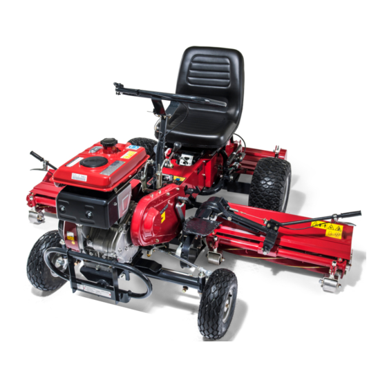
- Page 1 3-Unit Reel Mower Owner's Operating Manual Serial No. LM180E:21021- "Required reading" Read this manual before using the machine. Original Instructions Ver.1.2...
- Page 2 LM180E Greeting Thank you for purchasing the Baroness product. This manual describes the proper handling, adjustment, and inspection of your product. We hope you will use the product safely, and take advantage of its best performance. Keeping the Owner's Operating Manual Keep this manual in the box on the right side of the seat.
- Page 3 The operator is responsible for operating the product properly and safely. Maintenance service for this machine should be performed by a mechanic with expertise. If you have any questions concerning maintenance or genuine parts, please contact a Baroness dealer or Kyoeisha.
- Page 4 When replacing parts, be sure to use genuine Baroness parts or parts designated by Kyoeisha. Note that the Baroness product warranty may not apply to defects caused by the use of parts from other companies. Prior to use, carefully read the following manuals to thoroughly understand the contents for safe and correct operation.
-
Page 5: Table Of Contents
LM180E Contents Safety .............. Page 1-1 Safe Operating Practices .......Page 1-2 Disposal ............Page 2-1 Recycle and Waste Disposal ......Page 2-2 Product Overview .......... Page 3-1 Specifications ..........Page 3-2 Names of Each Section ......... Page 3-3 Regulation Decals ..........Page 3-4 Safety Signs and Instruction Signs .... - Page 6 LM180E Contents...
-
Page 7: Safety
LM180E Safety Safe Operating Practices ...... Page 1-2 Training ..........Page 1-2 Preparation ..........Page 1-2 Operation ..........Page 1-3 Maintenance .......... Page 1-4 Storage ..........Page 1-4 Page 1-1... -
Page 8: Safe Operating Practices
LM180E Safety Failure to adequately follow these safety Never allow children or people unfamiliar precautions may cause an accident resulting in with these instructions to use or service the injury or death. machine. Local regulations may restrict the age of the... -
Page 9: Operation
LM180E Safety If fuel is spilled, do not attempt to start the Do not stop or start suddenly. engine but move the machine away from Look behind and down before backing up to the area of spillage and avoid creating any be sure of a clear path. -
Page 10: Maintenance
LM180E Safety Reduce the throttle setting during engine Keep hands and feet away from moving run-out. parts. If possible, do not make adjustments with the Do not direct discharge material toward engine running. anyone. Avoid discharging material against a wall or Make sure that parts such as wires are not obstruction. -
Page 11: Disposal
LM180E Disposal Recycle and Waste Disposal ....Page 2-2 About Recycle ........Page 2-2 About Waste Disposal ......Page 2-2 Page 2-1... -
Page 12: Recycle And Waste Disposal
LM180E Disposal Recycle and Waste Disposal About Recycle Recycling battery etc. is recommended for environmental conservation and economical use of resources. It may be required by local laws. About Waste Disposal Make sure that waste generated when servicing or repairing the machine is disposed of in accordance with local regulations. -
Page 13: Product Overview
LM180E Product Overview Specifications ........Page 3-2 Specifications .........Page 3-2 Sound Pressure Level ......Page 3-3 Sound Power Level ....... Page 3-3 Vibration Level ........Page 3-3 Names of Each Section ......Page 3-3 Regulation Decals ........Page 3-4 Positions of Regulation Decals ....Page 3-4 Description of Regulation Decals .. -
Page 14: Specifications
LM180E Product Overview Specifications Specifications Type LM180E Total length 215 cm During 208 cm operation Dimensions Total width During 185 cm transport Total height Steering wheel 102 cm Total weight Machine (empty fuel tank) 381 kg Minimum turning radius 230 cm Model MITSUBISHI GB300LN... -
Page 15: Names Of Each Section
LM180E Product Overview Sound Pressure Level Names of Each Section Sound Pressure Level This machine was confirmed to have a continuous A-weighted sound pressure level of 89dB by measuring identical machines in accordance with the procedure specified in ISO 5395-1:2013. -
Page 16: Regulation Decals
LM180E Product Overview Regulation Decals Specification Decal (For Europe) Positions of Regulation Decals CE mark indicates that the machine sold in the EU nations complies with the EU requirements. The Specification decal indicates the CE marking, model , and weight, etc. -
Page 17: Safety Signs And Instruction Signs
If they are damaged, become dirty, or peel off, replace them with new ones. Part numbers for decals that need to be replaced are listed in the parts catalog. Order them from a Baroness dealer or Kyoeisha. wvzv36-001 Positions of Safety Decals and Instruction... -
Page 18: Description Of Safety Decals And Instruction Decals
LM180E Product Overview Description of Safety Decals and Caution to Mutilation Decal Instruction Decals K4205001600 Operation Decal DECAL, CAUTION TO MUTILATION Warning LM180E-1001Z0 STICKER, OPERATION May cut your hand or leg - Stop the cutter rotation and engine. Otherwise you may get injured. - Page 19 LM180E Product Overview Caution to Noise Decal K4205001330 DECAL, CAUTION TO NOISE bwu9po-001 Caution to Noise Decal_001 Decal on Reading Owner's Operating Manual K4205001560 Decal, read Owner's Operating Manual Warning Read the Owner's Operating Manual. tpfrw8-001 Decal on Reading Owner's Operating Manual_001...
- Page 20 LM180E Product Overview Page 3-8 Safety Signs and Instruction Signs...
-
Page 21: Handling Instructions
LM180E Handling Instructions Inspections ..........Page 4-2 Diff-lock Pedal ........Page 4-19 Parking Brake Lever ......Page 4-20 Reel Cutter (Cutting Cylinder) and Bed Knife (Bottom Blade) ...... Page 4-2 Move ............Page 4-20 Cover ............. Page 4-2 Traveling Operation ......Page 4-20 Roller ............. -
Page 22: Inspections
LM180E Handling Instructions Cover Inspections Inspection of Covers Inspect the machine according to the maintenance schedule so that you will be able to Warning take advantage of its optimum performance for a long period of time. If you have removed the covers during... -
Page 23: Air Cleaner
LM180E Handling Instructions Install the urethane element into the paper Air Cleaner element. Inspection of Air Cleaner Install the air cleaner cover. The air cleaner is a component that removes dirt from the intake air to prevent wear of the cylinder liners and piston rings so that the engine will always operate smoothly. -
Page 24: Belt
LM180E Handling Instructions Belt Around The Engine Inspection of Belt Inspection around The Engine Check the fuel system parts for loosened or Warning cracked joints and leakage. Replace the parts if necessary. The engine must be stopped when the belt is inspected. -
Page 25: Fuel
LM180E Handling Instructions The appropriate engine oil level should be Securely tighten the oil level gauge. between the upper and lower limit lines on the gauge. bgmiun-031 Supply of Engine Oil_001 bgmiun-015 Oil level gauge (oil filling port) Inspection of Engine Oil_002... -
Page 26: Fuel Strainer
LM180E Handling Instructions Fuel Strainer Supply of Fuel Inspection of Fuel Strainer Warning The fuel strainer is installed near the fuel tank Do not supply fuel above the FULL level of the and cleans the fuel that enters the carburetor. -
Page 27: Transmission
LM180E Handling Instructions Filling of Transmission Oil Important During installation, prevent contamination with Important dirt or dust. If the fuel is contaminated with dirt, dust, etc., Do not mix different types of transmission oil. the fuel flow will become insufficient. -
Page 28: Tightening Torques
LM180E Handling Instructions Tightening Torques Important Refer to the Tightening Torque table. Note that the Baroness product warranty may not apply to defects caused by incorrect or overtorque tightening, etc. Standard Tightening Torques Bolts and Nuts Important A number of bolts are used in each part of this machine. - Page 29 LM180E Handling Instructions General bolt Strength classification 4.8 Nominal diameter tib3yb-001 kgf-cm lb-in 3 - 5 30.59 - 50.99 26.55 - 44.26 7 - 9 71.38 - 91.77 61.96 - 79.66 14 - 19 142.76 - 193.74 123.91 - 168.17 29 - 38 295.71 - 387.49...
-
Page 30: Principal Tightening Torques
LM180E Handling Instructions Principal Tightening Torques Tightening Torque by Model LM180E Tighten the following bolts and nuts at the torque specified in the table. For thread locking adhesive, apply a mild to high-strength thread locker (ThreeBond 1322 or equivalent anaerobic sealant). -
Page 31: Adjustment Before Work
LM180E Handling Instructions With the nuts A and B, adjust the Adjustment before Work engagement between the reel cutter (cutting cylinder) and the bed knife (bottom blade) so Adjustment of Seat that newspaper (two to three sheets) will be Use the seat adjustment lever to adjust the cut by the edge of both blades when the seat back and forth. -
Page 32: Adjustment Of Cutting Height
LM180E Handling Instructions Install the belts for left and right mower units and for rear mower unit. Adjustment of Cutting Height Important The front wheel is provided to prevent the reel cutter (cutting cylinder) from damaging a convex portion of the lawn surface. -
Page 33: Procedure To Start/Stop Engine
LM180E Handling Instructions Procedure to Start/Stop Engine Procedure to Stop Engine Set the reel rotation lever to the "Stop" Start/Stop of Engine position. Procedure to Start Engine Shift the throttle lever to the "Low speed" position , and continue idling for 1 to 2 Caution minutes. -
Page 34: Operation Method
LM180E Handling Instructions Operation Method Cautions for when You Leave The Machine Caution If the brakes are not sufficiently effective, use the wheel stoppers to secure the machine. 6n6oux-205 Caution Positions of Operation Decals_003 Never park the machine on a slope. -
Page 35: Operation Method
LM180E Handling Instructions Description of Operation Decals Change Mark Engine Switch Mark LM180E-0802Z0 DECAL, SHIFTING K4203000670 This indicates the positions of the change Decal, engine switch lever. This indicates the engine switch positions. an8lyj-005 rcyo1p-010 Change Mark_001 Engine Switch Mark_001... -
Page 36: Throttle Lever
LM180E Handling Instructions Clutch Operation Mark Brake Mark Clutch operation mark K4209001200 This illustrates “Engage/Disengage" of the DECAL, BRAKE traveling clutch. It illustrates the locking position for the parking brake. 91a7z5-003 7elqr2-002 Clutch Operation Mark_001 Brake Mark_001 Engage Throttle Lever... -
Page 37: Change Lever
LM180E Handling Instructions Change Lever Traveling Clutch Lever Important Warning Do not change the lever position during Be careful of the machine suddenly traveling. Otherwise, the transmission will be accelerating when the machine starts to travel damaged. if the throttle lever is set to the "High speed"... -
Page 38: Reel Rotation Lever
LM180E Handling Instructions Reel Rotation Lever Mower Unit Lifting lever Left and Right Mower Units Caution Set the reel rotation lever to the engaged Caution position immediately before mowing. At all Before raising or lowering the mower units, other times, be sure to leave the reel clutch make sure that there are no people around lever in the disengaged position. -
Page 39: Brake Pedal
LM180E Handling Instructions Brake Pedal Rear Mower Unit The brake pedal is located in the right foot Important area. In order to stop the machine, depress the Before raising or lowering the mower units, brake pedal with your right foot until the pedal make sure that there are no people around hits the pedal stopper. -
Page 40: Move
LM180E Handling Instructions Parking Brake Lever Caution Under any circumstances drive the machine at Caution such a speed that you can stop it immediately for emergencies. Never park the machine on a slope. Caution Important Make sure not to touch rotating tires with your Be sure to release the parking brake before hands or legs. -
Page 41: Cutting Work
LM180E Handling Instructions Storage Frame Raise all mower units. Before Long-Term Storage Set the change lever to the "Neutral" Cleaning position. Remove dirt, grass clippings, oil stains etc. ・ Remove the wheel stoppers. completely from the main vehicle and Release the parking brake. - Page 42 LM180E Handling Instructions Page 4-22 Storage...
-
Page 43: Maintenance
LM180E Maintenance Maintenance Precautions ..... Page 5-2 Maintenance Schedule ......Page 5-2 Adjusted Values ........Page 5-5 Jacking Up The Machine .......Page 5-6 About Jacking Up The Machine .....Page 5-6 Jack-up Points ........Page 5-6 Greasing ..........Page 5-7 About Greasing ........Page 5-7 Greasing Points ........ -
Page 44: Maintenance Precautions
Use tools appropriate for each maintenance operation. Important For the safe and best performance of your machine, use Baroness genuine parts for replacement and accessories. Please note that our product warranty may be void if you use non-genuine parts for replacement or accessories. - Page 45 LM180E Maintenance Maintenance Item Remarks Clean engine and circumference ○ of the muffler cover Clean circumference of the recoil ○ ...
- Page 46 ○ Bed knife) required *1: Consult your local Baroness Dealer for this service. ・ *2: Refer to the Engine's Owner's Manual. ・ The values for consumables are not guaranteed.
-
Page 47: Adjusted Values
LM180E Maintenance Adjusted Values Diff-lock wire Create a slight play Clearance between pedal stopper and Brake pedal 5 - 7 mm (0.20 - 0.28 in) brake pedal Clearance between rod-tension metal Traveling clutch 7 - 8 mm (0.28 - 0.31 in) -
Page 48: Jacking Up The Machine
LM180E Maintenance Jack-up Points Jacking Up The Machine About Jacking Up The Machine Warning When replacing a tire or beginning any other maintenance or repairs, be sure to chock the wheels to prevent the machine from moving. Before jacking up the machine, park it on a... -
Page 49: Greasing
LM180E Maintenance Front axle, center Transmission axle case, left rwyt62-012 rwyt62-016 Jack-up Points_002 Jack-up Points_006 Front axle, right Transmission axle case, right rwyt62-013 rwyt62-017 Jack-up Points_003 Jack-up Points_007 Front axle, left Greasing About Greasing Since there may be adhesion or damage due to lack of grease on moving parts, they must be greased. -
Page 50: Greasing Points
LM180E Maintenance Front wheels Greasing Points There is one point each on the left and the right wheels. Grease nipples are installed in the following locations. Add grease every 50 hours of operation. 8bq62b-056 Greasing Points_002 Front wheel front pin... - Page 51 LM180E Maintenance Mower frame Handle tension There is one point each on the left and the right mower units. 8bq62b-070 Greasing Points_008 8bq62b-059 Greasing Points_005 Mower lifting arm There is one point each on the left and the right mower units.
- Page 52 LM180E Maintenance Rear roller There is one point each on the left and the right of each unit. 8bq62b-066 Greasing Points_012 Mower tension 8bq62b-067 Greasing Points_013 8bq62b-068 Greasing Points_014 Page 5-10 Greasing...
-
Page 53: Lubrication
LM180E Maintenance Handle tension Lubrication There is one point. About Lubrication It is necessary to lubricate moving parts so that they will not become stuck or damaged. The locations where lubricant is used are indicated in "Lubricating Points". Apply the lubricant. -
Page 54: Back Lapping
(when you face the mower unit from the left) [Back lapping powder mixed with oil; or gel by hand to check the sharpness. compound (Baroness genuine abrasive)], Check the sharpness at entire range (three Brush, Socket (opposite side 27). or four points from left edge to right one) of the reel cutter (cutting cylinder). -
Page 55: Sharpening Of Reel Cutter (Cutting Cylinder)
In addition, if the reel cutter (cutting cylinder) becomes worn and its shape conical, perform cylindrical grinding to return it to a cylindrical shape. For sharpening the reel cutter (cutting cylinder), contact your dealer or Baroness unless you have a grinding machine. Maintenance Work Page 5-13... - Page 56 LM180E Maintenance Note: The outer diameter of the reel cutter (cutting cylinder) shaft is 25.4 mm (1.00 in). ok5ueg-007 Sharpening of Reel Cutter (Cutting Cylinder)_002 Reel cutter (cutting cylinder) blade Sharpening width for outer diameter of reel cutter (cutting cylinder)
-
Page 57: Replacement Of Reel Cutter (Cutting Cylinder)
LM180E Maintenance Note: Replacement of Reel Cutter (Cutting The outer diameter of the reel cutter (cutting Cylinder) cylinder) shaft is 25.4 mm (1.00 in). Caution Both the reel cutter (cutting cylinder) and the bed knife (bottom blade) are edged tools. -
Page 58: Replacement Of Bed Knife (Bottom Blade)
LM180E Maintenance Replacement of Bed Knife (Bottom Blade) Removing/Installing Tires Front Tires Caution Follow the steps below to remove the front Both the reel cutter (cutting cylinder) and the tires: bed knife (bottom blade) are edged tools. Loosen the bolts. -
Page 59: Adjustment Of Belt Tension
LM180E Maintenance Place the tire jack beneath the jack-up point Belt Installation Locations of the rear wheel transmission area securely, then raise it until the tire lifts off Belts are installed in this machine at the the ground. following locations. - Page 60 LM180E Maintenance Follow the same steps to adjust the belts on Reel Rotation Lever the mower unit on the opposite side. Loosen the adjustment bolt, then change the length of the rod. Adjust the clearance between the rod- tension metal fitting and the collar to be 7 - 8 mm (0.28 - 0.31 in), when the reel rotation...
- Page 61 LM180E Maintenance Rear Mower Tension Rear Mower Unit Loosen adjusting nut A. Loosen adjusting nut A. Tighten adjusting nut B, then change the Tighten adjusting nut B, then change the length of the rod. length of the rod. Lower the rear mower unit on a level...
-
Page 62: Adjustment Of Parking Brake
LM180E Maintenance Adjustment of Parking Brake Caution If the brake wire is cut, the machine will be unable to stop. If the brake wire is cracked or damaged, replace it with a new one immediately. Caution If the parking brake is not sufficiently effective when you pull the parking brake lever, adjust the brake wire. -
Page 63: Adjustment Of Brake
LM180E Maintenance Adjustment of Brake Caution If the brake is not applied effectively even if you depress the pedal up to the stopper, adjust the brake rod. Pull the parking brake lever completely and make sure that the brake is effectively applied. -
Page 64: Adjustment Of Diff-Lock Wire
LM180E Maintenance Adjustment of Diff-lock Wire Adjustment of Mower Stopper Lower the left and right mower units, then Important engage the reel rotation lever. If the diff-lock seems ineffective when you Loosen the nut, then adjust the position of depress the diff-lock pedal, adjust the diff-lock the adjustment bolt so that the mower wire. -
Page 65: Change Of Air Cleaner
LM180E Maintenance Follow the same steps to adjust the hook When the hook metal fitting returns to its wire of left mower. original position by spring tension as soon as you release the lever, raise the rear mower lifting arm and make sure that the... -
Page 66: Change Of Engine Oil
LM180E Maintenance Supply new engine oil through the oil filling Change of Engine Oil port. The engine oil quantity is 1.0 dm (1.0 L). Caution Position the machine so that the engine is Be careful with hot oil, which could cause level, and then check the engine oil level burns if it contacts your skin. - Page 67 LM180E Maintenance Attach the oil filling port cap and oil level plug. 4sr81t-001 Change of Transmission Oil_001 Oil filling port Oil level plug Drain plug Check underneath the machine for oil leakage. Maintenance Work Page 5-25...
- Page 68 LM180E Maintenance Page 5-26 Maintenance Work...
- Page 72 1-26, Miyuki-cho, Toyokawa-city, Tel : +81 - 533 - 84 - 1390 Head Office Aichi-pref, 442-8530 JAPAN Fax : +81 - 533 - 84 - 1220 LM180E--UM--GBZ/22C-00-S.K E03a[LM180E_EU03a]...
Need help?
Do you have a question about the LM180E and is the answer not in the manual?
Questions and answers