Table of Contents
Advertisement
Quick Links
Advertisement
Table of Contents

Related Manuals for Baroness LM18G


Summary of Contents for Baroness LM18G
- Page 1 Ver.1.3...
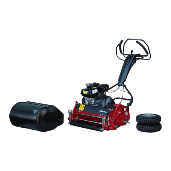
- Page 2 Introduction This service manual describes the steps to maintain the Baroness Greens Mower LM18G, LM56G and LM66T as well as the resources for diagnosing malfunctions and other issues. The content is organized by categories of representative maintenance methods. Please refer to the appropriate chapter to address your mower’s particular condition.
-
Page 3: Table Of Contents
Table of Contents ......................1 Specifications ......................1 Part Names .................... 2 Maintenance Schedule ..................... 2 Locations for Greasing ................. 3 How to Handle a Product Malfunction ....................... 6 Required Tools ....................6 Note for Inspection ................7 [1] Replacing reel cutter and bedknife .......... -
Page 4: Specifications
Specifications Model LM18G LM56G LM66T Length (with grass catcher) 54.5 in. (138.5cm) 55.3 in. (140.5cm) Width (without travelling wheels) 33.1 in. (84.2cm) 37 in. (94.2cm) 40 in. (103cm) Height (handle) 45.2in. (114.7 cm) no groomer 211 lbs. (95.7kg) 202 lbs. (91.5kg) 214 lbs. -
Page 5: Maintenance Schedule
Maintenance Schedule Maintenance Before use Every 8hr Every 10hr Every 50hr Cleaning of each part/inspection of tightening Inspection and addition of fuel Inspection and cleaning of air cleaner Inspection and addition of engine oil Engine oil change [SAE30/0.6dm (0.6L)] Only after the initial operation Inspection and cleaning of recoil starter dust proofing net Cleaning of each part/inspection of tightening... -
Page 6: How To Handle A Product Malfunction
How to Handle a Product Malfunction Has the bedknife become curvy? Is the mowing height on both sides adjusted to be the same? Restore the bedknife to its normal condition Adjust the mowing height. by lapping, grinding, or replacing it. Is the bedknife cracked? Lightly engage the blades. - Page 7 Are genuine parts used for the blades? Is the grain size of lapping Use the lapping powder powder #200 - #400? of #200 - #400 grain size. Replace the blades with genuine parts. Is the blade surface of the bedknife too rough? Have you recently applied Work sand into the greens.
- Page 8 Is the roller bracket secured? Tighten and secure the bracket. Replace the locking screw. Is the mower adjusted to the correct mowing height? Adjust the mowing height. Does the front roller rattle up and down? Replace the bearing on the front roller. Replace the front roller shaft.
-
Page 9: Required Tools
Required Tools *Tool sizes are indicated in mm. Screw wrench 7 10 13 17 19 22 x 1 24 x 2 Allen key wrench 2 5 6 Longnose pliers Pin remover Stop ring pliers For opening & closing Screwdriver Flathead x 2 Slide gauge Clearance gauge (thickness gauge) 0.5 x 2 (included tool) -
Page 10: Replacing Reel Cutter And Bedknife
[1] Replacing reel cutter and bedknife * Please always wear gloves during this replacement as it could be dangerous. Traveling wheel 1) Set up the stand first, and then remove the traveling wheels on both sides. Stand 2) Place the mower on a stable workbench and lower the handle. - Page 11 6) Open the clutch cover [5-1,2,50]. Clutch cover 7) Remove the bolts [1-25] on both sides that are holding the reel cover. Bolt Models equipped with a groomer 8) Unscrew the tall nuts [8-58] on both sides and the right case locking bolt [8-60], and then remove the groomer Ass’y.
- Page 12 9) Loosen the lock nut [1-21] on the cutter pin on both sides, and then loosen the cutter pins [1-20]. * When the blade adjusting nut [1-1] is tightened, the bedknife is lowered (to avoid contact between the reel and bedknife at the time of assembly). (Lock nut, cutter pin, cam bush) 10) Remove the two bolts [1-25] that secure the bedknife base arm and bedknife base COMP.
- Page 13 14) Remove the 6 bolt 10 , 6 S Washer , Clutch retainer spring [6-56], and remove the H/L change lever [6-91] 6SWasher 6 bolt 10 from left side cover. Clutch retainer spring H/L change lever 15) Loosen the hexagon socket head bolt on the wheel 8 Hexagon socket head bolt 25 driving fitting, amd then remove the fitting.
- Page 14 Models not equipped with a groomer Remove the bolt and nut, and detach the cover [1-28]. Cover Remove the two left nuts [1-32], washer [1-34], and spring [1-35]. * The nuts are left-hand threaded. 2SPCC washer 1635 3.2 compression spring 26.922 16 left hand threaded nut 3P1.5...
- Page 15 19) Detach the O-ring P18 [1-33] and the pin lock cover [1-44] from the reel shaft on the left frame, and using a pin remover remove the needle roller [1-45] and left bearing collar [1-43]. Left bearing collar * Make sure that the 20-tooth reel gear has been re- Pin lock cover moved.
-
Page 16: How To Replace The Oil Seal And Tapered Roller Bearing
[2] How to replace the oil seal and tapered roller bearing 1) Using a flathead screwdriver, remove the oil seal [1-38]. * Be careful not to scratch the frame. Oil seal 2) Remove the bearing core[1-36] by hammering a flat- head screwdriver equally around the bearing. - Page 17 6) Hammer the oil seal [1-38] into the housing. * The oil seal needs to be hammered deep inside while Oil seal paying attention to the direction of the housing and oil seal. Housing 7) Hammer the tapered bearing core [1-36] into the hous- ing [1-58].
- Page 18 11) Insert the spline side of the reel cutter into the left frame [6-43]. * Be careful not to damage the oil seal. Reel cutter (spline side) 12) Set up the reel cutter by reversing the steps to remove it. * Please refer to pages 12-12).
- Page 19 16) Insert an item such as a wooden hammer handle into Reel cutter the reel cutter to prevent the reel from turning. 17) Set the spring [1-35] and the gear [8-46] on the right reel housing while making sure that the direction and Spring the order are correct.
-
Page 20: How To Replace The Bedknife
[3] How to replace the bedknife * Place the bedknife COMP on a stable workbench dur- ing the replacement. Bedknife base Remove the bedknife [1-17,18,64,65,66,67,68] by loos- ening the screw [1-19] with an impact driver or punch. Bedknife Attaching the bedknife Place the bedknife base [1-15,16,69] on a stable workbench and attach the bedknife [1-17,18,64,65,66,67,68] to it. - Page 21 3) Align the punch mark of the cam bush on both sides to the mowing direction. Punch mark 4) Make sure that the reel cutter and bedknife contact. Reel cutter No clearance Clearance Bedknife 5) Try to cut a strip of newspaper from left to right while gently turning the reel (at 5 to 6 different places) Reel cutter * If the reel and bedknife are not yet engaged correctly.
- Page 22 8) Tighten the fulcrum seat [1-5] to the right and left frames with the bolt [1-4]. In case there are clearance Frame Fulcrum seat between the frame and the fulcrum seat, set 1-5 piec- es of 0.4SPCC washer 1220 for clearance adjustment to clear the clearance.
- Page 23 4) To make sure that the newspaper is cut uniformly on both sides of the cutter, loosen the blade adjusting nut Reel cutter on the side where the newspaper is cut better by turn- ing it slightly to “right” and adjust the side that doesn’t cut well by turning the nut slightly to “left”.
- Page 24 8) Install the H/L change lever [6-91] on the left cover 6S washer [6-89], attach the clutch retainer spring 5 [6-56], 6S 6 bolt 10 washer, 6 bolt 10. * Install the alignment finger of H/L change lever in the Clutch retainer 33-tooth reel gear and 42-tooth reel gear.
-
Page 25: Installing Of The Reel Cover
Models not equipped with a groomer Cover Attach the cover. * After making sure that the position of the O-ring [1-31] is correct, apply grease to it. Secure it tightly. [4] Installation of the reel cover 1) Set the reel cover into the groove behind the bedknife Reel cover Reel cover base. -
Page 26: Overhaul Of The Inside Of The Gear Case (Left)
[5] Overhaul of the inside of the gear case (left) 1) Set up the stand and remove the traveling wheels. 8 Hexagon socket head bolt 25 First, loosen the hexagon socket head bolt on the wheel driving fitting, and then remove the fitting. Remove the key [4-11] from the outer drum shaft. - Page 27 * Make sure that the changeover clutch lever is fitted Changeover clutch lever #7 gear tightly into the groove of the #7 gear. Apply enough grease to the gear tooth surface and bearings when assembling them. 5) Before attaching the cover, verify the gears’ movement and the number of the washers.
-
Page 28: Overhaul Of The Inside Of The Gear Case (Right)
[6] Overhaul of the inside of the gear case (right) 1) Set up the stand and remove the traveling wheels. First, loosen the hexagon socket head bolt [4-10] on the wheel driving fitting, and then remove the fitting. Remove the key [4-11] from the outer drum shaft. Hexagon socket Unscrew the six bolts [6-2] and remove the right cover head bolt... -
Page 29: Removing/Installing The Drum Assembly
[7] Removing / installing the drum assembly 1) Set up the stand and remove the traveling wheels. Left cover Remove the left cover [6-89]. * For more information, refer to sections “ [5] Overhaul Bolt [6-94] of the inside of the gear case (left)” or “ [6] Overhaul of the inside of the gear case (right)”. - Page 30 6) Gently hold both ends of the drum shaft with panto- graph jacks. (If no pantograph jack is available, use an alterna- tive and make sure that the drum shaft doesn’t come down.) 7) Remove the right and left drum housings [6-29] out- If the drum housing doesn't come ward.
-
Page 31: Disassembling/Assembling The Drum
[8] Disassembling / assembling the drum 1) Remove the outer drum shaft [4-15] by unscrewing the four bolts [4-16] on each side. * Secure the drum so that it doesn’t turn when loosening the bolts. Outer drum shaft 2) Remove the stop rings [4-17] on both sides. Separate the right from the left drum, and remove one of them. - Page 32 5) Have a new bearing and oil seal available, and apply Adjustment shim Bearing grease to the lip surface of the oil seal. Oil seal Adjustment Oil seal shim Bearing 6) Pay attention to the direction of the oil seal and bear- Oil seal ing.
-
Page 33: Removing/Installing/Disassembling/Assembling The Transmission Shaft
[9] Removing / installing / disassembling / assembling the transmission shaft 1) Set up the stand first, and then remove the traveling wheels on both sides. Traveling wheel Stand 2) Open the clutch cover and remove the clutch cover re- Clutch cover receiver ceiver [5-43,44,53]. - Page 34 6) Remove the nut [6-6] from the #3 gear. (left-hand threaded) Loosen the nut while holding the #1 gear with a flat- head screwdriver to keep the #3 gear from turning. (Hold the flathead screwdriver vertical to the teeth of the #1 gear.) 7) Remove the #3 gear by turning it clockwise.
- Page 35 10) Remove the 16-tooth right differential gear [6-66]. 11) First pull out the transmission shaft [6-36,80,101] in the direction of (as shown in the illustration). * Be careful not to lose the collar [6-33] or stop ring [6-34] Stop ring that are attached to the transmission shaft.
- Page 36 15) Tighten the gear by turning it all the way to the left, and then turn it back to the right a quarter of a circle. (left- hand threaded) Screwdriver Then, secure it with the lock nut [6-6]. * To avoid overstretching the transmission shaft, loosen it slightly.
-
Page 37: Disassembling/Assembling/Adjusting The Engine Clutch Area
[10] Disassembling / assembling / adjusting the engine clutch area 1) Fold the stand and let the drum touch the ground. Stand Horizontal 2) Set the changeover clutch lever to “Reel ON” position. 51-tooth gear Hold a flathead screwdriver against the 51-tooth gear 16-tooth gear [6-85] to keep it from turning, and then remove the nut from the 16-tooth [5-39]. - Page 38 6) Pull out the clutch shaft Ass’y. Clutch shaft Ass'y 7) Secure the clutch shaft Ass’y [5-24,25,51] on a vice. Waste cloth Pull out the tapered pin [5-27] using a pin remover. * When securing the clutch shaft Ass’y on a vice, wrap it Pin remover with a waste cloth to avoid scratching the surface.
- Page 39 11) Install in the following order: the collar [5-38], gear [5- A (51-tooth gear) 39], washer [5-40], disc spring washer [5-41], and nut 16-tooth gear [5-42]. When tightening the nut, hold a flathead screwdriver against the gear A (51-tooth gear) to keep it from turn- ing.
-
Page 40: Disassembling/Assembling/Adjusting The Brake
[11] Disassembling / assembling / adjusting the brake 1) Remove the two bolts [7-53] from the wire mounting Wire mounting bracket bracket. Brake Ass'y Remove the three bolts [7-53] from the brake Ass’y. 2) Remove the brake shoe using a flathead screwdriver. Brake shoe 3) With a rougher-grained sandpaper, polish the side of Brake shoe... - Page 41 6) Make sure the brake works by gripping the brake lever. Adjusting nut (If the brake doesn’t work, adjust it by tightening the adjusting nut of the brake wire.) * Set the brake shoe so that it does not always touch the brake drum.
-
Page 42: Disassembling/Assembling The Front Roller (With A Groomer)
[12] Disassembling / assembling the front roller (with a groomer) (As for the “with smooth front roller” and “with independent arm” types, follow the same steps ) 1) Remove the tall nut [2-1], disc spring washer [2-2], washer [2-3], and square-root bolt [2-7] from the left roller bracket on the left frame. - Page 43 7) Remove the oil seal [2-12] on both sides using a flat- head screwdriver. Oil seal Remove the stop ring [2-13]. Stop ring 8) Remove the front roller shaft by tapping the end which is sticking out more. Front roller shaft 9) Secure the removed front roller shaft on a vice, and Gear puller Bearing...
- Page 44 Preparation of replacement parts Have the replacement parts ready beforehand. Bearing 1) Apply some grease inside the oil seal [2-14]. Insert the bearing [2-15] into the oil seal firmly by tapping it with a wooden hammer. Oil seal Bearing Oil seal Bearing Oil seal 2) Apply grease to the lip surface of the oil seal [2-12]...
- Page 45 Using a driving tool, pound in the bearing and oil seal set Stop ring's groove all the way. (Drive them in below the stop ring’s groove.) Combined set of bearing and oil seal 4) Insert the stop ring [2-13]. Stop ring 5) Pound in the oil seal [2-12] on the outside.
- Page 46 Driving tool seal 8) Install the washer [2-8] and bracket [2-24] as shown in the illustration. Set and secure the flat end of the roller shaft into the Stopper bolt stopper bolt side, and lock it. Washer Lock nut 9) As shown in the illustration, match the bracket to the frame’s joint, and set the top of the bracket in the groove of the roller adjuster [2-21].
-
Page 47: Disassembling/Assembling The Front Roller (Without A Groomer)
12) Secure the roller with the tall nut [2-1], disc spring washer [2-2], washer [2-3], and square-root bolt [2-7] from the left bracket. After the roller is secured, inspect how the roller turns and the clearance between the roller and the bracket, and adjust accordingly. -
Page 48: Disassembling/Assembling/Adjusting The Front Groomer
[14] Disassembling / assembling / adjusting the front groomer 1) Refer to #1 of Equipped with the groomer on page 8 for removing the front groomer from the main unit. Left vertical housing 2) Remove the left vertical housing [8-63]. Left vertical housing 3) Pay attention to the direction of the oil seal [8-27]. - Page 49 6) Unscrew the four bolts [8-14,15] from the gear case cover, and then remove the cover [8-12]. Cover 7) Remove the 20-tooth vertical gear [8-30]. * Lock the nut [8-76] on the groomer using a screw 20-tooth vertical gear wrench, and remove the nut [8-29](left-hand threaded) which secures the 20-tooth vertical gear.
-
Page 50: Setting Of Dethatching Blades
10) Loosen the lock nut [8-72] and then the hollow set [8- 71]. Lock nut Hollow set 11) Secure the 17 special nut (Groomer Blade Locking nut) [8-76] on the spine side using a screw wrench, re- move the 17 special nut (Groomer Blade Locking nut) [8-76] on the opposite side first, and then remove the groomer’s collar and blade. -
Page 51: Adjusting The Front Groomer
3) Finally, insert the 17 special nut (Groomer Blade Lock- ing nut) [8-76], secure it with the hollow set [8-71], and lock it with the lock nut [8-72]. * Please do not tightened to much power. (Torque = 5~10 N m) 4) Install it in the vertical gear case [8-47] in the reverse order that it was disassembled. -
Page 52: Disassembling/Assembling The Igca Roller
[17] Disassembling/assembling the IGCA roller 1) Remove the washer [13-10], shaft [13-11], and snap pin [13-12] from the rear frame stay[7-92]. Snap pin Shaft Washer Rear frame stay 2) Raise the catcher arm and remove it from the mower. Catcher arm 3) Unfasten the bolts [13-15] of both side of the catcher arm. - Page 53 4) Remove the oil seal [13-22] on both sides using a flat- head screwdriver. Oil seal Remove the stop ring [13-21]. Stop ring 5) Remove the front roller shaft by tapping the end which is sticking out more. Front roller shaft 6) Secure the removed front roller shaft on a vice, and Bearing Gear puller...
- Page 54 Preparation of replacement parts Have the replacement parts ready beforehand. Bearing 1) Apply some grease inside the oil seal [13-20]. Insert the bearing [13-19] into the oil seal firmly by tapping it with a wooden hammer. Oil seal Bearing Oil seal Bearing Oil seal 2) Apply grease to the lip surface of the oil seal [13-22]...
- Page 55 Using a driving tool, pound in the bearing and oil seal set all the way. (Drive them in below the stop ring’s groove.) Stop ring's groove Combined set of bearing and oil seal 4) Insert the stop ring [13-21]. Stop ring 5) Pound in the oil seal [13-22] on the outside.
- Page 56 Driving tool seal 8) Screw bolt [13-15] and s washer [13-16] through hole on catcher arm [13-3] and into roller shaft [13-17]. Re- Catcher arm peat for both sides. S washer Bolt Roller shaft 9) Tighten and lock bolt [13-15]. To prevent roller shaft Roller shaft [13-17] from spinning, slide a screw driver through the hole of the roller shaft and hold for support while tight-...
-
Page 57: Adjusting The Arm Stopper
[18] Ajusting the arm stopper 1) Adjust distance of catcher arm [13-3] by tightening or loosening arm stoppers [13-5]. Stopper bracket Recommended space between the arm stopper and stopper brackets [13-6,8] should be 1 mm, when the front roller [3-37] is parallel with the roller [13-23] of catcher arm. -
Page 58: Reference
[19] Reference Wiring Diagrams (GX120) Black Blue White (1) ENGINE SWITCH (4) COIL ASSY., LAMP (2) SPARK PLUG (5) HEADLIGHT SWITCH (3) IGNITION COIL (6) HEADLIGHT... - Page 60 LM56GA--SM--USZ/09M-00-SPEC...
Need help?
Do you have a question about the LM18G and is the answer not in the manual?
Questions and answers