Baroness LM101 Owner's Operating Manual
Floating head greens mower
Hide thumbs
Also See for LM101:
- Owner's operating manual (81 pages) ,
- Owner's operating manual (88 pages)

Subscribe to Our Youtube Channel
Related Manuals for Baroness LM101


Summary of Contents for Baroness LM101
- Page 1 Floating Head Greens Mower Owner's Operating Manual Serial No. LM101:10906- "Required reading" Read this manual before using the machine. Original Instructions Ver.2.7...
- Page 2 LM101 Regulations USDA Forest Service Spark Arrester (For USA) The engine of this machine is equipped with a spark arrester. In some areas there are local, state, or federal regulations requiring that a spark arrester be used on the engine of this machine.
- Page 3 LM101 Greeting Thank you for purchasing the Baroness product. This manual describes the proper handling, adjustment, and inspection of your product. We hope you will use the product safely, and take advantage of its best performance. QR Code A QR code label is affixed on the machine.
- Page 4 The operator is responsible for operating the product properly and safely. Maintenance service for this machine should be performed by a mechanic with expertise. If you have any questions concerning maintenance or genuine parts, please contact a Baroness dealer or Kyoeisha.
- Page 5 When replacing parts, be sure to use genuine Baroness parts or parts designated by Kyoeisha. Note that the Baroness product warranty may not apply to defects caused by the use of parts from other companies. Prior to use, carefully read the following manuals to thoroughly understand the contents for safe and correct operation.
- Page 6 LM101 Introduction...
-
Page 7: Table Of Contents
LM101 Contents Safety .............. Page 1-1 Repair ..............Page 7-1 Safe Operating Practices .......Page 1-2 Precautions for Repair ........Page 7-2 Adjustment and Replacement ......Page 7-2 Disposal ............Page 2-1 Appended Table ..........Page 8-1 Recycle and Waste Disposal ......Page 2-2 Tightening Torques ........ - Page 8 LM101 Contents...
-
Page 9: Safety
LM101 Safety Safe Operating Practices ...... Page 1-2 Training ..........Page 1-2 Preparation ..........Page 1-2 Operation ..........Page 1-3 Maintenance .......... Page 1-4 Storage ..........Page 1-4 Page 1-1... -
Page 10: Safe Operating Practices
LM101 Safety Failure to adequately follow these safety Preparation precautions may cause an accident resulting in injury or death. Evaluate the terrain to determine what accessories and attachments are needed to Danger properly and safely perform the job. This product is designed to ensure safe... -
Page 11: Operation
LM101 Safety If the handlebar has noticeable play, be sure Remember there is no such thing as a safe to adjust or repair them before operating the slope. machine. Travel on grass slopes requires particular care. Replace faulty mufflers. To guard against overturning, follow these Operation instructions. -
Page 12: Maintenance
LM101 Safety Take care when loading or unloading the Keep all nuts, bolts and screws tight to be machine into a trailer or a truck. sure the equipment is in safe working Load or unload the machine in a flat and condition. -
Page 13: Disposal
LM101 Disposal Recycle and Waste Disposal ....Page 2-2 About Recycle ........Page 2-2 About Waste Disposal ......Page 2-2 Page 2-1... -
Page 14: Recycle And Waste Disposal
LM101 Disposal Recycle and Waste Disposal About Recycle Recycling battery etc. is recommended for environmental conservation and economical use of resources. It may be required by local laws. About Waste Disposal Make sure that waste generated when servicing or repairing the machine is disposed of in accordance with local regulations. -
Page 15: Product Overview
LM101 Product Overview Specifications ........Page 3-2 Specifications .........Page 3-2 Sound Pressure Level ......Page 3-3 Sound Power Level ....... Page 3-3 Vibration Level ........Page 3-3 Carbon Dioxide (CO2) Emissions ..Page 3-3 Names of Each Section ......Page 3-4 Regulation Decals ........Page 3-5... -
Page 16: Specifications
LM101 Product Overview Specifications Specifications Model LM101 Name Floating Head Greens Mower with grass Total length 141 cm 55.51 in catcher without Dimensions Total width traveling 94 cm 37.01 in wheel Steering Total height 117 cm 46.06 in handle Machine (empty fuel tank) 114 kg 251.32 lb... -
Page 17: Sound Pressure Level
LM101 Product Overview The factory default maximum engine rpm is 3,100 rpm. : Weight (Machine) includes *1 parts. : The indicated lowest mowing height is for general application. It may be adjusted according to the state of green and the bed knife to be installed. -
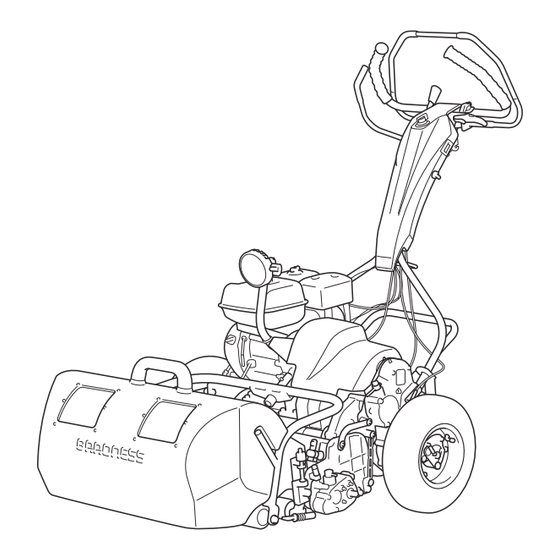
Page 18: Names Of Each Section
LM101 Product Overview Names of Each Section Handle Throttle lever Engine switch Main clutch lever Clutch lock lever Brake lever Engine Engine clutch cover Light Reel cutter Bed knife Front roller Rear roller Grass catcher roller Grass catcher Groomer Groomer clutch lever... -
Page 19: Regulation Decals
LM101 Product Overview Regulation Decals Specification Decal (For EU) Positions of Regulation Decals The Specification decal indicates the model and weight, etc. B,C,D 56063F89 Positions of Regulation Decals_001 450597AD Serial number plate Specification Decal_001 Specification Decal CE Mark CE mark... -
Page 20: Safety Signs And Instruction Signs
If they are damaged, become dirty, or peel off, replace them with new ones. Part numbers for decals that need to be replaced are listed in the parts catalog. Order them from a Baroness dealer or Kyoeisha. Positions of Safety Decals and Instruction Decals... -
Page 21: Description Of Safety Decals And Instruction Decals
LM101 Product Overview Description of Safety Decals and PTO Caution Decal Instruction Decals K4205001760 Handling Caution Decal DECAL, CAUTION PTO K4205002150 Warning DECAL, CAUTION HANDLING May catch your arm - Keep away from PTO moving parts during the engine running. - Page 22 LM101 Product Overview Caution to Noise Decal Greasing Each 10-Hours Decal K4205001330 K4209000370 DECAL, CAUTION TO NOISE DECAL, GREASING EACH 10-HOURS Add grease every 10 hours. bwu9po-001 Caution to Noise Decal_001 rc9mq6-001 Greasing Each 10-Hours Decal_001 Engine Oil Warning Decal...
-
Page 23: Operation Decals
LM101 Product Overview Description of Operation Decals Operation Decals Engine Switch Mark Positions of Operation Decals ENGINE SWITCH MARK It illustrates the positions of the engine switch. rcyo1p-003 Engine Switch Mark_001 Light Switch Mark Note: Depending on the specifications, this function may not be available. - Page 24 LM101 Product Overview ON/OFF Mark A (unit clutch) Reel Rotation Indication Mark K4203001140 K4203001690 STICKER, ON/OFF A (unit clutch) STICKER, REEL ROTATION It shows ON/OFF of the unit clutch. It illustrates High / Low speed of the reel cutter rotation speed.
- Page 25 LM101 Product Overview Red Alignment Mark 10300 Note: Depending on the specifications, this function may not be available. K4209001230 DECAL, ALIGNMENT 10300 (SET OF 2PCS) Affix the decals in indicative positions on the grass catcher for operational support. wxhvbx-001 Red Alignment Mark 10300_001...
- Page 26 LM101 Product Overview Page 3-12 Operation Decals...
-
Page 27: Description Of Functions
LM101 Description of Functions Light Switch ........... Page 4-2 Engine Switch ........Page 4-2 Throttle Lever .........Page 4-2 Throttle Lever .........Page 4-2 Brake Lever ..........Page 4-3 Clutch Lock Lever ........Page 4-3 Main Clutch Lever ........Page 4-3 Drum Clutch Lever .........Page 4-4 Unit Clutch Lever ........ -
Page 28: Light Switch
LM101 Description of Functions Light Switch Throttle Lever Note: Note: Depending on the specifications, this function Depending on the specifications, this function may not be available. may not be available. The light switch is located in the handle panel. The throttle lever is located in the handle and Flip up the switch to turn on the light, and down enables you to adjust the engine rpm. -
Page 29: Brake Lever
LM101 Description of Functions Brake Lever Caution Avoid quick operation. Carefully and slowly operate the machine. The brake lever is located in the handle. Grip the brake lever to activate braking and the travel of the machine is stopped. Grip the lock lever while gripping the brake lever 6zsd1y-002 to lock the brake lever with braking applied. -
Page 30: Drum Clutch Lever
LM101 Description of Functions Drum Clutch Lever Caution Operate and set the lever to the proper position in accordance with the purpose when the main clutch lever set to the OFF position. The drum clutch lever is located at the rear of the right frame side. -
Page 31: Engine Clutch Cover
LM101 Description of Functions Groomer Clutch Lever Note: Depending on the specifications, this function may not be available. Caution Operate and set the lever to the proper position in accordance with the purpose when the main clutch lever set to the OFF position. -
Page 32: Instruments
LM101 Description of Functions Instruments Hour Meter Important The battery of this hour meter can not be replaced. If the battery power is burned out, replace the hour meter with a new one. The hour meter indicates the accumulated operation time of the engine. -
Page 33: Handling Instructions
LM101 Handling Instructions Preparation for Use ....... Page 5-2 Transporting .........Page 5-14 Installing the Handle ......Page 5-2 Transporting Procedure ....... Page 5-14 Connection of Engine Switch Cord ..Page 5-2 Installing The Stand ....... Page 5-2 Confirmation of The Operation ....Page 5-3 Inspection and Cleaning ....... -
Page 34: Preparation For Use
LM101 Handling Instructions The crimp terminal is secured to the engine Preparation for Use crankcase with a hexagon bolt. Installing the Handle Put the handle pin on the left frame into the hole at the left-side lower edge of the handle. -
Page 35: Inspection And Cleaning
LM101 Handling Instructions Tighten the bolt, washer, and nut at the left Make sure that the reel cutter (cutting side of the stand that were temporarily cylinder) and the bed knife (bottom blade) secured. are not cracked. Check to see how much the reel cutter (cutting cylinder) and the bed knife (bottom blade) are worn. -
Page 36: Air Cleaner
LM101 Handling Instructions Remove dirt and dust from the paper Air Cleaner element with blowing air or patting. Inspection of Air Cleaner Assemble the paper and urethane elements. The air cleaner is a component that removes Attach the air cleaner elements with the dirt from the intake air to prevent wear of the screw. -
Page 37: Roller
LM101 Handling Instructions Make sure that the wire is not crushed. Roller Make sure that the wire is not bent. Inspection of Rollers Make sure that the wire is not corroded or rusted. Make sure that there is no abrasion nor adhesion of the roller. -
Page 38: Engine Oil
LM101 Handling Instructions Engine Oil Supply of Engine Oil Inspection of Engine Oil Important Do not supply too much engine oil. Otherwise, Important the engine may be damaged. Screw the oil level gauge firmly. Stop the engine, wait for 10 to 20 minutes... -
Page 39: Fuel
LM101 Handling Instructions Fuel Inspection of Fuel Quantity Level the machine and then remove the tank cap to inspect fuel quantity from the fill port. 2e4emp-010 Fuel Supply_001 Fuel strainer Filling opening Maximum limit of fueling 2.5 cm (0.98 in) -
Page 40: Liquid Leakage
LM101 Handling Instructions Dry with compressed air. Bolts and Nuts Inspection of Bolts and Nuts Important The bolts and nuts may be loosened at the earlier stage of the use. Be sure to retighten or replace before operating the machine whenever there is any abnormality. -
Page 41: Adjustment Before Work
LM101 Handling Instructions Make sure that the engine switch is in the Adjustment before Work "OFF" position. Adjustment of Handle Position The height of the handle can be adjusted according to the operator's working position. Move the handle adjusters supporting the handle up or down and fix them with the bolts. - Page 42 LM101 Handling Instructions Main clutch lever Choke lever Clutch lock lever Close Open Important Set the fuel cock to the "Open" position. Return the starter grip slowly to its original position after the engine starts. Do not let go of the pulled starter grip since it may cause damage to the machine.
-
Page 43: Parking And Stopping
LM101 Handling Instructions Procedure to Stop Engine Fuel cock Close Don't grip the main clutch lever. Open Parking and Stopping Procedure to Leave The Machine Caution If the brakes are not sufficiently effective, use the wheel stoppers to secure the machine. -
Page 44: Cutting Work
LM101 Handling Instructions Removing/Installing Traveling Tires Cutting Work Cutting Work Important Remove the traveling tires before cutting Warning work. Do not operate on a steep slope. Traveling tires are used to travel. Removing Traveling Tires: Caution Stop the engine. Do not start to move or stop the machine Flip down the stand. -
Page 45: Removing/Installing Grass Catcher
LM101 Handling Instructions Install the traveling tire to the drum shaft. Important Make sure that the wheel mount plate is grooved on the drum shaft. Otherwise the tires will come off. x9pzjh-007 Removing/Installing Traveling Tires_003 Traveling tire Repeat the same process for removing the opposite traveling tire. -
Page 46: Transporting
LM101 Handling Instructions Transporting Transporting Procedure Caution When loading and unloading the machine, wear non-slip shoes and travel slowly. Important When securing the machine with a rope, do not tie the rope to the engine. Important When securing the machine with a rope, be careful not to bend any wires. -
Page 47: Maintenance
LM101 Maintenance Precautions for Maintenance ....Page 6-2 Position of Mower during Maintenance ........... Page 6-2 Greasing ..........Page 6-3 About Greasing ........Page 6-3 Greasing Points ........Page 6-3 Lubrication ..........Page 6-7 About Lubrication ........Page 6-7 Lubricating Points ........Page 6-7 Adjustment and Replacement .... -
Page 48: Precautions For Maintenance
Set the handle so that the maintenance Important stand can stand upright. Use Baroness genuine parts for replacement and accessories. Our product warranty may be void if you use non-genuine parts for replacement or accessories. -
Page 49: Greasing
LM101 Maintenance For maintenance of the machine without the ・ Greasing Points traveling wheels: Grease nipples are installed in the following Caution locations. The engine malfunction does not occur even Add grease to A every 10 hours, and B every when the machine tilting toward the handle 50 hours. - Page 50 LM101 Maintenance Left frame #2 shaft No. of greasin Location Greasing period points Upper side of left framecover Mower #1 shaft Left frame #2 shaft Left frame #4 shaft Differential gear Right frame #2 shaft 8bq62b-300 Right gear case...
- Page 51 LM101 Maintenance Right gear case Right side 8bq62b-304 8bq62b-457 Greasing Points_008 Greasing Points_011 Transmission gear case Transmission shaft spline Grease the transmission shaft spline. 8bq62b-305 0E6D8AFA Greasing Points_009 Transmission shaft Greasing Points_012 There are one location each on the right and Arm mounting hitch fulcrum left.
- Page 52 LM101 Maintenance Reel housing Right side There are one location each on the right and left. Left side 8bq62b-312 Greasing Points_017 Groomer gear case Note: 8bq62b-309 Depending on the specifications, this Greasing Points_014 Right side function may not be available.
-
Page 53: Lubrication
LM101 Maintenance Right side Handle Main clutch lever ・ 8bq62b-315 Greasing Points_020 8bq62b-447 Cam bush Greasing Points_023 There are one location each on the right and Lubrication left. Apply 0.5 g (0.001 lb) of grease to outer About Lubrication perimeter of the cam bush pipe according to It is necessary to lubricate moving parts so that the maintenance schedule. -
Page 54: Adjustment And Replacement
(cutting cylinder) and the bed knife Note: (bottom blade) so that Takumi Paper Depending on the specifications, this (Baroness genuine paper strips) or function may not be available. newspaper (one piece) will be cut cleanly by the edge of both blades when the blades in their entirety come slightly into contact with each other via the cutter adjustment nuts. -
Page 55: Adjustment Of Cutting Height
LM101 Maintenance If the sharpness is not improved by the ・ adjustment: Perform back lapping to the reel cutter (cutting cylinder). fofmiy-006 Adjustment of Blade Engagement_002 Cutter adjustment nut Loosen Tighten Adjustment of Cutting Height Important This applies the set cutting height that differs from the actual cutting height. - Page 56 LM101 Maintenance Remove the left and right washer B and nut B, and remove the rear roller assy from the frame. 33i8xn-002 Cutting Height and Thickness of Bed Knife (Bottom Blade)_001 Standard blade 3kws2a-019 Tipped blade Adjustment of Rear Roller_002...
- Page 57 LM101 Maintenance Standard cutting stance ・ Adjustment of Front Roller Set the slide caliper to the required cutting height, adjust the position of the bottom of the head of the cutting height setting screw on the cutting height gauge, and then securely lock it with a wing nut.
-
Page 58: Adjustment Of Groomer
LM101 Maintenance Bring the cutting height gauge into contact Tighten the nuts securing the left and right with the front roller and rear roller at the left roller brackets, and fix them securely. and right ends of the mowing part. - Page 59 LM101 Maintenance Bring the cutting height gauge into contact Vertical blade with the front roller and rear roller at the left Groomer setting screw and right ends of the mowing part. Cutting height gauge Front roller Groomer height Loosen the nut B securing the left side groomer adjustment screw.
-
Page 60: Adjustment Of Cutter Adjustment Spring
LM101 Maintenance Bring the cutting height gauge into contact Note: with the front roller and rear roller at the left When not using the front groomer, there is and right ends of the mowing part again, and no need to change the set height of the check that it is at the desired groomer height. -
Page 61: Adjusting Cam
LM101 Maintenance Note: Adjusting CAM The figure below shows the situation when you see from the left side. Turn the cam bush on both sides of the bed The right side is mirror reversed. knife (bottom blade), and the blade can be raised and lowered respectively by maximum 0.3 mm (0.012 in). -
Page 62: Back Lapping
Caution Do not perform back lapping with any other persons. Have the following items ready: Strips of Takumi Paper (Baroness genuine paper strips) or newspaper, Abrasive [Back lapping powder mixed with oil; or gel compound (Baroness genuine abrasive)], Brush. zhz6po-009... - Page 63 LM101 Maintenance Insert one or two strips of Takumi Paper or Connect the lapping machine or the lapping newspaper into the space between the reel handle to the lapping bolt on the machine. cutter (cutting cylinder) and the bed knife (bottom blade) at an angle of 90 degrees.
-
Page 64: Sharpening Of Reel Cutter (Cutting Cylinder)
For sharpening the reel cutter (cutting cylinder), contact your dealer or Baroness unless you have a grinding machine. Caution Both the reel cutter (cutting cylinder) and the ok5ueg-006 bed knife (bottom blade) are edged tools. -
Page 65: Replacement Of Reel Cutter (Cutting Cylinder)
LM101 Maintenance Sharpening is necessary when the reel The criteria for replacing the reel cutter (cutting cutter (cutting cylinder) reaches a condition cylinder) are described below. described below. However, these criteria are only a reference and do not guarantee performance like that of When the sharpening width (length of a new reel cutter (cutting cylinder). -
Page 66: Replacement Of Bed Knife (Bottom Blade)
LM101 Maintenance Installing The Reel Cutter Collar Caution Torque wrench 11.5 mm (0.453 in) Both the reel cutter (cutting cylinder) and the bed knife (bottom blade) are edged tools. Mower with Groomer: Handle them carefully, since they could cut your hands and feet. -
Page 67: Removing/Installing The Bed Knife Base
LM101 Maintenance Standard blade Lower the roller bracket so that it does not Replace the bed knife (bottom blade) before it contact the reel cover, and then remove the no longer has a front face. bolts. d5gd5v-002 5ttm1g-005 Replacement of Bed Knife (Bottom Blade)_001... - Page 68 LM101 Maintenance Remove the bolts, and then remove the Place down the cutting section, and then rear roller Assy. remove the bed knife base COMP. 5ttm1g-008 5ttm1g-011 Removal of Bed Knife Base_004 Removal of Bed Knife Base_007 Rear roller Assy...
- Page 69 LM101 Maintenance Installation of Bed Knife Base Collar Compression spring Caution Cutter adjustment bolt Bed knife base COMP Both the reel cutter (cutting cylinder) and the Mower frame bed knife (bottom blade) are edged tools. Handle them carefully, since they could cut Temporarily install the left and right cutter your hands and feet.
- Page 70 LM101 Maintenance Make sure that the bed knife (bottom blade) Adjust the positions of the cam bushes so contacts the reel cutter (cutting cylinder). that both sides cut. kx7caa-005 kx7caa-012 Installation of Bed Knife Base_004 Installation of Bed Knife Base_006...
- Page 71 LM101 Maintenance Bed knife base COMP Lock nut Collar Cutter pin Compression spring Cam bush Cutter adjustment bolt Install the rear roller Assy. Install the bed knife base COMP. Tighten the left and right cutter adjustment nuts evenly on both sides so that the cutter pin mounting holes of the bed knife base and cam bush are aligned.
-
Page 72: Removing/Installing The Bed Knife
LM101 Maintenance Removing/Installing The Bed Knife Caution Wear gloves when touching edged tools to Removing The Bed Knife avoid cutting your hands. Caution Caution Both the reel cutter (cutting cylinder) and the bed knife (bottom blade) are edged tools. While operations are performed with the front Handle them carefully, since they could cut of the machine raised, it may fall. -
Page 73: Replacement Of Air Cleaner Element
LM101 Maintenance Important Be sure to use engine oil that is classified as API Service Grade SE or higher, with an SAE Viscosity that is appropriate for the operating environment (ambient temperature). Important Screw the oil level gauge firmly. 4miqko-002... -
Page 74: Storage
LM101 Maintenance Storage Long-Term Storage Follow the instructions below for long-term storage of the machine. Cleaning Remove dirt, grass clippings, oil stains etc. ・ completely from the main vehicle and engine. Replacing oil Inspect and replace the engine oil and ・... -
Page 75: Repair
LM101 Repair Precautions for Repair ......Page 7-2 Adjustment and Replacement ....Page 7-2 Adjustment of Brake ......Page 7-2 Adjustment of Engine Clutch Section ..Page 7-2 Page 7-1... -
Page 76: Precautions For Repair
Caution It may result in an unexpected accident if the Important left and right brakes are not equally effective. Use Baroness genuine parts for replacement Make sure that the left and right brakes are and accessories. equally effective. Our product warranty may be void if you use... - Page 77 LM101 Repair Adjustment of Engine Clutch Adjustment of Clutch Wire Adjust the clearance between the engine Important clutch and clutch facing so that it will be 0.5 - 1.0 mm (0.020 - 0.039 in) when the main Make sure that the wire is not cracked or clutch lever set to the "ON"...
- Page 78 LM101 Repair Adjustment of Clutch Spring The factory default setting of the clutch spring total length is 63.0 mm (2.48 in). The longer the spring is set, the lighter clutch handling is provided. The shorter, the heavier. Make adjustment with the spring adjustment nut so that the total length of the clutch spring will be 63.0 mm (2.48...
-
Page 79: Appended Table
LM101 Appended Table Tightening Torques ........Page 8-2 Standard Tightening Torques ....Page 8-2 Principal Tightening Torques ....Page 8-4 Maintenance Schedule ......Page 8-5 List of Adjusted Values ......Page 8-7 Troubleshooting Procedures of Aftercut Appearance ......Page 8-8 Scalping ..........Page 8-8 Angled Mismatch ........ -
Page 80: Tightening Torques
LM101 Appended Table Tightening Torques Important Refer to the Tightening Torque table. Note that the Baroness product warranty may not apply to defects caused by incorrect or overtorque tightening, etc. Standard Tightening Torques Bolts and Nuts Important A number of bolts are used in each part of this machine. - Page 81 LM101 Appended Table General bolt Strength classification 4.8 Nominal diameter tib3yb-001 kgf-cm lb-in 3 - 5 30.59 - 50.99 26.55 - 44.26 7 - 9 71.38 - 91.77 61.96 - 79.66 14 - 19 142.76 - 193.74 123.91 - 168.17 29 - 38 295.71 - 387.49...
-
Page 82: Principal Tightening Torques
LM101 Appended Table Principal Tightening Torques Tightening Torque by Model LM101 Tighten the following bolts and nuts at the torque specified in the table. For thread locking adhesive, apply a middle strength thread locker (ThreeBond 1322 or equivalent anaerobic sealant). -
Page 83: Maintenance Schedule
LM101 Appended Table Maintenance Schedule LM101 ●・・・Inspect, adjust, supply, clean (first time) ○・・・Inspect, adjust, supply, clean ●・・・Replace (first time) △・・・Replace Maintenance Item Remarks Check bolts and nuts ○ Check fuel ○... - Page 84 LM101 Appended Table Maintenance Item Remarks Check work lamp illumination ○ Adjust handle position ○ Check safety lock of main clutch ...
-
Page 85: List Of Adjusted Values
Regrind blades (Reel cutter) ○ as and when required *1: Consult your local Baroness Dealer for this service. ・ *2: Refer to the Engine's Owner's Manual. ・ The values for consumables are not guaranteed. -
Page 86: Troubleshooting Procedures Of Aftercut Appearance
LM101 Appended Table Angled Mismatch Troubleshooting Procedures of Aftercut Appearance Is the cutting height on both sides adjusted to be the same? Scalping Adjustment of cutting height Is the roller bracket secured? Is the bed knife (bottom blade) chipped? Tightening to secure... -
Page 87: Overlap Marks
LM101 Appended Table Overlap Marks Has the bed knife (bottom blade) become curved? Back lapping Surface grinding of bed knife (bottom blade) Replacement of bed knife (bottom blade) Loosening of blade engagement After loosening blade engagement, streaks still appear. Adjustment of spring compression length Is the spring pressure for the adjustment nut too light? (See "Adjustment of Cutter Adjustment Spring".) -
Page 88: Blade Does Not Cut
LM101 Appended Table Blade Does Not Cut Are genuine parts used for the blades? Is the grit size of the lapping Use lapping powder with a grit Replacement of blades with genuine parts powder #200 – #400? size of #200 – #400. -
Page 89: Uneven Blade Engagement
LM101 Appended Table Uneven Blade Engagement The unevenness is a difference of tightening torque between the left and right cutter adjustment nuts, or blade engagement on only one side, which cannot be adjusted. Promptly resolve the issue in order to maintain the optimum performance of the machine. - Page 90 LM101 Appended Table Page 8-12 Troubleshooting Procedures of Aftercut Appearance...
- Page 91 1-26, Miyuki-cho, Toyokawa-city, Tel : +81 - 533 - 84 - 1390 Head Office Fax : +81 - 533 - 84 - 1220 Aichi-pref, 442-8530 JAPAN LM101---UM--GBZ/24D-00-S.K...
Need help?
Do you have a question about the LM101 and is the answer not in the manual?
Questions and answers