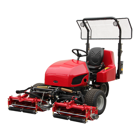
Baroness LM331 Service Manual
3-unit surround & trim mower
Hide thumbs
Also See for LM331:
- Owner's operating manual (115 pages) ,
- Owner's operating manual (94 pages) ,
- Owner's operating manual (103 pages)
Table of Contents
Advertisement
Quick Links
Advertisement
Chapters
Table of Contents

Subscribe to Our Youtube Channel
Related Manuals for Baroness LM331


Summary of Contents for Baroness LM331
- Page 1 3-Unit Surround & Trim Mower Service Manual Serial No. LM331:10001- Ver.1.0...
- Page 2 The information described in this manual is subject to change for improvement without prior notice. When replacing parts, be sure to use genuine Baroness parts or parts designated by Kyoeisha. Note that the Baroness product warranty may not apply to defects caused by the use of parts from other companies.
-
Page 3: Table Of Contents
LM331 Contents Safety .............. Page 1-1 Relating to Operating Machine and Mower Unit .............Page 7-7 Safe Operating Practices .......Page 1-2 Reference ............Page 8-1 Safety Signs and Instruction Signs ....Page 1-5 Specifications ..........Page 8-2 Disposal ............Page 2-1 Maintenance Schedule ........Page 8-4 Recycle and Waste Disposal ...... - Page 4 LM331 Contents...
-
Page 5: Safety
LM331 Safety Safe Operating Practices ...... Page 1-2 Training ..........Page 1-2 Preparation ..........Page 1-2 Operation ..........Page 1-3 Maintenance and storage ...... Page 1-4 Safety Signs and Instruction Signs ..Page 1-5 About Safety Signs and Instruction Signs ............Page 1-5... -
Page 6: Safe Operating Practices
LM331 Safety Failure to adequately follow these safety Never allow children or people unfamiliar precautions may cause an accident resulting in with these instructions to use or service the injury or death. machine. Local regulations may restrict the age of the... -
Page 7: Operation
LM331 Safety Add fuel before starting the engine. Never Never operate across the face of the remove the cap of the fuel tank or add fuel slope, unless the machine is designed for while the engine is running or when the this purpose. -
Page 8: Maintenance And Storage
LM331 Safety Never operate while people, especially Maintenance and storage children, or pets are nearby. Disengage drives on level ground, lower the Slow down and use caution when making attachments, set parking brake, stop engine turns and crossing roads and sidewalks. -
Page 9: Safety Signs And Instruction Signs
Disconnect the negative terminal replaced are listed in the parts catalog. first and the positive last. Reconnect positive Order them from a Baroness dealer or first and negative last. Kyoeisha. Make sure that parts such as wires are not touching each other and that their covers have not come off. - Page 10 LM331 Safety Page 1-6 Safety Signs and Instruction Signs...
-
Page 11: Disposal
LM331 Disposal Recycle and Waste Disposal ....Page 2-2 About Recycle ........Page 2-2 About the Waste disposal ...... Page 2-2 Page 2-1... -
Page 12: Recycle And Waste Disposal
LM331 Disposal Recycle and Waste Disposal About Recycle Recycling battery etc. is recommended for environmental conservation and economical use of resources. It may be required by local laws. About the Waste disposal Make sure that waste generated when servicing or repairing the machine is disposed of in accordance with local regulations. -
Page 13: Maintenance Standards And Maintenance
LM331 Maintenance standards and maintenance Unit conversion ........Page 3-2 Inch–millimeter conversion table ... Page 3-2 US unit–SI unit conversion table ....Page 3-3 Maintenance standards ......Page 3-4 List of Maintenance Specifications ..Page 3-4 Tightening torques ........ Page 3-5 Standard tightening torques ....Page 3-5 Principal tightening torques .... -
Page 14: Unit Conversion
LM331 Maintenance standards and maintenance Unit conversion Inch–millimeter conversion table 1 mm = 0.03937 in 1 in = 25.4 mm Fractions Decimals Fractions Decimals 1/64 0.015625 0.397 33/64 0.515625 13.097 1/32 0.03125 0.794 17/32 0.53125... -
Page 15: Us Unit-Si Unit Conversion Table
LM331 Maintenance standards and maintenance US unit–SI unit conversion table To Convert Into Multiply By Miles Kilometers 1.609 Yards Meters 0.9144 Feet Meters 0.3048 Linear Measurement Feet Centimeters 30.48 Inches Meters 0.0254 Inches Centimeters 2.54 Inches Millimeters 25.4 mile Square Miles Square Kilometers 2.59... -
Page 16: Maintenance Standards
LM331 Maintenance standards and maintenance Maintenance standards List of Maintenance Specifications Engine model Kubota D902-E4B-LMKY-1 No load rpm 1.450 - 2,800 rpm API Service grade class CF or 3.7 dm (3.6 L) (0.98 gal (US)) Engine oil higher, SAE Viscosity grade... -
Page 17: Tightening Torques
LM331 Maintenance standards and maintenance Tightening torques Standard tightening torques Bolts and Nuts Important A number of bolts are used in each part of this machine. Be sure to re-tighten the bolts and nuts, because they may be loosened at the earlier stage of the use. - Page 18 LM331 Maintenance standards and maintenance Heat-treated bolt Strength classification 8.8 Strength classification 10.9 Nominal diameter 10.9 tib3yb-002 tib3yb-003 kgf-cm lb-in kgf-cm lb-in 5 - 7 50.99 - 71.38 44.26 - 61.96 7 - 10 71.38 - 101.97 61.96 - 88.51 8 - 11 81.58 - 112.17...
- Page 19 LM331 Maintenance standards and maintenance Fittings with parallel threads (O-ring seal type) The tightening torques for fittings with parallel threads (O-ring seal method) are shown in the table below. Tightening an adjustable joint forcibly with a spanner or other such tool to secure it to a set position could damage the adjustable joint, its washers, and other parts.
-
Page 20: Principal Tightening Torques
LM331 Maintenance standards and maintenance Principal tightening torques Tightening Torque by Model LM331 Tighten the following bolts and nuts at the torque specified in the table. For thread locking adhesive, apply a middle strength thread locker (ThreeBond 1322 or equivalent anaerobic sealant). -
Page 21: Jacking Up The Machine
LM331 Maintenance standards and maintenance Jacking up the machine Jack-up Points Front right frame About the Jacking up the machine Front left frame Rear right frame Warning Rear left frame When replacing a tire or beginning any other Front right frame maintenance or repairs, be sure to chock the wheels to prevent the machine from moving. -
Page 22: Greasing
LM331 Maintenance standards and maintenance Rear left frame Front left frame rwyt62-096 b5geiy-006 Jack-up Points_005 Lifting Points_003 Lifting Points Greasing About Greasing Important Since there may be adhesion or damage due Be sure to use adequately strong cables. to lack of grease on moving parts, they must be greased. -
Page 23: Greasing Points
LM331 Maintenance standards and maintenance Lift arm fulcrum Greasing Points Mower unit #1 Grease nipples are installed in the following There is one greasing point on the lift arm locations. fulcrum connected to the mower unit. Add grease every 50 hours of operation. - Page 24 LM331 Maintenance standards and maintenance Brake pedal shaft fulcrum Tension lever 8bq62b-272 8bq62b-275 Greasing Points_005 Greasing Points_008 Brake lever shaft Neutral cam lever Add grease every 100 hours of operation or every year, whichever comes earlier. 8bq62b-276 Greasing Points_009 8bq62b-273...
-
Page 25: Mower Unit Layout
LM331 Maintenance standards and maintenance Front wheel brake lever Mower coupling There is one greasing point each on the left Mower unit #2 and #3 and right sides. There is one greasing point each on the Left side couplings connecting the mower units. - Page 26 LM331 Maintenance standards and maintenance Page 3-14 Mower Unit Layout...
-
Page 27: Hydraulic System
LM331 Hydraulic system Maintenance ........... Page 4-2 About Maintenance ........Page 4-2 Specifications ........Page 4-3 Specifications .........Page 4-3 Hydraulic System Layout ....... Page 4-4 Flow of Hydraulic Oil ......Page 4-6 General instructions ......Page 4-10 Hydraulic hose ........Page 4-10 Hydraulic fitting ........Page 4-10 Towing .......... -
Page 28: Maintenance
LM331 hydraulic system. For information on daily checks, maintenance and handling of the machine, please refer to the separate LM331 Owner's Operating Manual and Parts Catalog. In order to maintain the integrity of the hydraulic device, it cannot be disassembled and repaired. -
Page 29: Specifications
LM331 Hydraulic system Specifications Specifications KYB PSV-16AHG-2 16.4 cm /rev Displacement (1.00 in /rev) Piston pump (P) 20.6 MPa High-pressure relief set (210 kgf/cm pressure (2,987 psi) 4.9 cm /rev Displacement (0.30 in /rev) Charge pump (P1) 0.6 MPa Charge relief set pressure... -
Page 30: Hydraulic System Layout
LM331 Hydraulic system Hydraulic System Layout dwb7jb-014 Hydraulic System Layout_001 Wheel motor 2-160BS4S Steering cylinder Stack valve Piston pump Filler neck breather Gear motor Orbitrol Wheel motor 2-200BS4S Up/down cylinder 2WD/3WD changeover valve Stop valve Hydraulic oil filter Inline check valve... - Page 31 LM331 Hydraulic system Inline check valve Gear motor The check valve is forced open when the This is located in each unit to rotate the reel cracking pressure is reached, allowing oil to cutter. This converts the fluid energy from...
-
Page 32: Flow Of Hydraulic Oil
LM331 Hydraulic system Flow of Hydraulic Oil Flow of Oil during 3WD Forward Traveling 8sgrtg-002 Flow of Oil during 3WD Forward Traveling_001 shows the flow of oil. shows flow of supply oil of the rear wheel motor. The flow of oil shows that for 3WD forward traveling. - Page 33 LM331 Hydraulic system Flow of Oil during 2WD Forward Traveling 8sgrtg-001 Flow of Oil during 2WD Forward Traveling_001 shows the flow of oil. shows flow of supply oil of the rear wheel motor. Oil flows in the direction of the arrow between the rear wheel motor and the 2WD/3WD changeover valve.
- Page 34 LM331 Hydraulic system Flow of Oil during Raising Mower Unit, with Power Steering Turning to Left qwbqfy-009 Flow of Oil during Raising Mower Unit, with Power Steering Turning to Left_001 shows the flow of oil. The flow of oil shows that for raising the mower unit, turning the power steering to left.
- Page 35 LM331 Hydraulic system Flow of Oil during Cutting with Mower Unit a4d9ch-008 Flow of Oil during Cutting with Mower Unit_001 shows the flow of oil. The figure above shows the oil flow when cutting with the mower unit. shows the port name.
-
Page 36: General Instructions
LM331 Hydraulic system Hydraulic fitting General instructions Bite type tube fitting Hydraulic hose Preliminary tightening (Preset) Warning Cut the tube at the designated length at a Be sure to depressurize the hydraulic system right angle. before maintaining or repairing it. - Page 37 LM331 Hydraulic system Matchmark the zero point and further tightening of 3/4 to one turn will cause the sleeve to bite into the tube. w7s31b-004 Bite type tube fitting_004 Fix the temporary tightening tool onto the w7s31b-007 vise and apply hydraulic oil to the threads, tapered part, and sleeve.
- Page 38 LM331 Hydraulic system Note: Adjustable Elbow ■ For direct tightening, use the fitting body to follow procedures 1 to 5 when using a temporary tightening tool, and set the zero point. Further tighten for 1 and 1/4 turn from the zero point.
- Page 39 LM331 Hydraulic system Make sure that the thread portion, sheet After fitting the opposite screw, tighten the surface of the O-ring port, and O-ring are lock nut while holding the main body with not contaminated with foreign objects. a spanner etc. to ensure that the setting Apply oil or grease to the sheet surface position does not change.
- Page 40 LM331 Hydraulic system Before connecting the joint, wind sealing Wrap it in clockwise direction (direction to ・ tape on the taper thread portion. tighten the screw). "How to Use the Sealing Tape" (Page Wrapping in the opposite direction may 4-14) cause the tape to be easily peeled off.
-
Page 41: Towing
LM331 Hydraulic system Towing Hydraulic circuit failure The hydraulic traveling circuit of this equipment Important is made up of a closed circuit. In the event of failure of the hydraulic Going over the limit of towing may lead to the equipment of the hydraulic circuit, debris and failure of hydraulic equipment. -
Page 42: Hydraulic Circuit Flow
LM331 Hydraulic system Hydraulic circuit flow Traveling circuit Forward Traveling (3WD) pizs5v-009E Forward Traveling (3WD)_001 Page 4-16 Hydraulic circuit flow... - Page 43 LM331 Hydraulic system Reverse Traveling (3WD) pizs5v-011E Reverse Traveling (3WD)_001 Hydraulic circuit flow Page 4-17...
- Page 44 LM331 Hydraulic system Forward Traveling (2WD) pizs5v-010E Forward Traveling (2WD)_001 Page 4-18 Hydraulic circuit flow...
- Page 45 LM331 Hydraulic system Reverse Traveling (2WD) pizs5v-012E Reverse Traveling (2WD)_001 Hydraulic circuit flow Page 4-19...
-
Page 46: Raise/Lower Circuit
LM331 Hydraulic system Raise/lower circuit Up/Down Cylinder Raising qhyyzc-016E Up/Down Cylinder Raising_001 Page 4-20 Hydraulic circuit flow... - Page 47 LM331 Hydraulic system Up/down cylinder lowering (operation) qhyyzc-017E Up/down cylinder lowering (operation)_001 Hydraulic circuit flow Page 4-21...
-
Page 48: Steering Circuit
LM331 Hydraulic system Steering circuit Steering Cylinder Counter-Clockwise Turning zujak2-008E Steering Cylinder Counter-Clockwise Turning_001 Page 4-22 Hydraulic circuit flow... - Page 49 LM331 Hydraulic system Steering Cylinder Clockwise Turning zujak2-009E Steering Cylinder Clockwise Turning_001 Hydraulic circuit flow Page 4-23...
-
Page 50: Reel Rotation Circuit
LM331 Hydraulic system Reel Rotation Circuit Reel Positive Rotation (Operation) k46fs2-010E Reel Positive Rotation (Operation)_001 Page 4-24 Hydraulic circuit flow... - Page 51 LM331 Hydraulic system Reel Reverse Rotation (Back Lapping) k46fs2-009E Reel Reverse Rotation (Back Lapping)_001 Hydraulic circuit flow Page 4-25...
-
Page 52: Special Tool
LM331 Hydraulic system Special Tool List of Special Tools Pressure gauge for high pressure measurements Pressure: For the range of 0 - 35 MPa For the range of 0 - 5,076.40 psi K4701000010 For the range of 0 - 356.90 kgf/cm Primarily used for measuring the pressure of high-pressure parts. - Page 53 LM331 Hydraulic system Pressure gauge seal Inserted between the pressure gauge K4701000050 and the pressure gauge joint. vasdfi-005 Pressure gauge joint K4701000040 Used as a joint for pressure pipes. vasdfi-006 Gauge valve Used to temporarily shut off the fluid to...
- Page 54 LM331 Hydraulic system Cast iron T-joint PT3/8 PF3/8 Used to insert the pressure gauge K3024000042-Y between the hydraulic hoses. vasdfi-013 Special adapter PF1/4 PT3/8 Used as an adapter for the T-joint K3009000042-Y during pressure measurements. vasdfi-015 Adapter 1013-9 Two pieces of them are used as...
- Page 55 LM331 Hydraulic system Screw cap (male) PF1/4 Used as a plug when the hydraulic K3008000522-Y hose is removed. q9c6v6-001 Screw cap (female) PF1/4 Used as a plug when the hydraulic K3008000482-Y hose is removed. q9c6v6-002 Screw cap (male) PF1/8 Used as a plug when the hydraulic K3008000532-Y hose is removed.
- Page 56 LM331 Hydraulic system 90-degree elbow 1033-6 Used as an elbow for connecting to K3001060002-Y special bushings during pressure measurements. q9c6v6-039 Adapter 1013-6 Used as an adapter for connecting to K3000060002-Y branched joints during pressure measurements. q9c6v6-008 Branched joint 1/2 Used for branches into joints off the...
- Page 57 LM331 Hydraulic system Branched joint 1/4 Used for branches into joints off the K3090000312 flow path for oil pressure measurements. q9c6v6-049 Special Tool Page 4-31...
-
Page 58: Measurement
LM331 Hydraulic system Review the measuring method before Measurement starting measurement. Note Before measurement, check for poor adjustment, clogging or breakage. The most effective way of solving problems in Warm up the hydraulic oil before starting the hydraulic system is to use a measuring pressure measurement. -
Page 59: Traveling Circuit
LM331 Hydraulic system Traveling Circuit Forward Traveling (3WD) Pressure gauge pizs5v-008E Forward Traveling (3WD)_001 Measurement Page 4-33... - Page 60 LM331 Hydraulic system Move the 2WD/3WD changeover lever to Caution the 3WD side. Before starting pressure measurement, make Remove the upper hydraulic hose from the sure that there are no people around the left side front wheel motor, and install machine.
- Page 61 LM331 Hydraulic system Use a sling or other equipment to apply resistance to the rear hook so that the machine does not move forward. pizs5v-006 Forward Traveling (3WD)_006 Rear hook Open the gauge valve of the hydraulic pressure measurement tool.
- Page 62 LM331 Hydraulic system Reverse Traveling (3WD) Pressure gauge pizs5v-007E Reverse Traveling (3WD)_001 Page 4-36 Measurement...
- Page 63 LM331 Hydraulic system Move the 2WD/3WD changeover lever to Caution the 3WD side. Before starting pressure measurement, make Remove the lower hydraulic hose from the sure that there is no people around the left side front wheel motor, and install...
- Page 64 LM331 Hydraulic system Use a sling or other equipment to apply resistance the frame lower side so that the machine does not move backward. pizs5v-003 Reverse Traveling (3WD)_006 Frame lower side Open the gauge valve of the hydraulic pressure measurement tool.
-
Page 65: Up/Down Circuit (Rise)
LM331 Hydraulic system Up/Down Circuit (Rise) Pressure gauge z4kw7w-052E Up/Down Circuit (Rise)_001 Measurement Page 4-39... - Page 66 LM331 Hydraulic system Remove the hydraulic pressure Caution measurement port plug of the stack valve using an M6 hexagon wrench. Before starting pressure measurement, make sure that there are no people around the machine. Caution Use a pressure gauge and hydraulic hose which can withstand the pressure of 13.7 MPa...
-
Page 67: Steering Circuit (Turning To Left)
LM331 Hydraulic system Steering Circuit (Turning to Left) g2hgdk-010E Steering Circuit (Turning to Left)_001 Measurement Page 4-41... - Page 68 LM331 Hydraulic system Install branched joint 1/4 between the Caution removed shrinking side hydraulic hose and steering cylinder. Before starting pressure measurement, make sure that there are no people around the machine. Caution Use a pressure gauge and hydraulic hose which can withstand the pressure of 6.9 MPa...
-
Page 69: Charge Circuit
LM331 Hydraulic system Charge Circuit Pressure gauge zg85f8-046E Charge Circuit_001 Measurement Page 4-43... - Page 70 LM331 Hydraulic system Install branched joint 3/8 between the Caution removed hydraulic hose and branched elbow. Before starting pressure measurement, make sure that there are no people around the machine. Before pressure measurement, perform the following operations. Install the gauge bulb and high-pressure hose to the pressure gauge for extremely low pressure measurements.
-
Page 71: Reel Rotation Circuit
LM331 Hydraulic system Reel Rotation Circuit Pressure gauge dmxdti-026E Reel Rotation Circuit_001 Measurement Page 4-45... - Page 72 LM331 Hydraulic system Caution Stack valve Hydraulic pressure measurement port Before starting pressure measurement, make plug sure that there are no people around the machine. Install a 90-degree elbow 1033-6 to the stack valve hydraulic pressure measurement port. Install an hydraulic pressure measurement...
-
Page 73: Adjustment
LM331 Hydraulic system Raising speed too fast: ・ Caution Turn the slow return valve dial Measure the pressure with the positive clockwise. rotation. Tighten the hollow screw. Open the gauge valve of the hydraulic pressure measurement tool. Start the engine, and rev it up to the maximum rpm. - Page 74 LM331 Hydraulic system Page 4-48 Adjustment...
-
Page 75: Electrical System
LM331 Electrical system Maintenance ........... Page 5-2 About Maintenance ........Page 5-2 Specifications ........Page 5-2 Electrical Part Layout ......Page 5-2 Electrical components ......Page 5-5 About the Electrical components ... Page 5-5 Proximity Switch ........Page 5-6 Seat Switch ..........Page 5-8 Rocker Switch ........Page 5-8... -
Page 76: Maintenance
LM331 electrical system. For information on daily checks, maintenance and handling of the machine, please refer to the separate LM331 Owner's Operating Manual and Parts Catalog. For details on handling the battery, please refer to the separate Battery Instruction Manual. - Page 77 LM331 Electrical system Relay (REEL "STOP") Hour meter Diode unit Relay (REEL "TURN ON") Fuel gauge Tank unit Relay (PEDAL "NEUTRAL") Water temperature gauge Pilot box Relay (REEL "DOWN") Proximity switch (NO (+) (black)) Mini fuse box Relay (REEL Fwd-Rev)
- Page 78 LM331 Electrical system T2. Solenoid timer It controls the reverse rotation of the stack It is associated with the fuel solenoid pull, valve for mower rotation according to switch and operates for only 3 seconds when the operation. key switch is ON, and functions as the timer It is located under the hood.
-
Page 79: Electrical Components
LM331 Electrical system 2. Pilot box Electrical components The status of the engine charge, thermo- start and engine oil pressure is displayed About the Electrical components with illumination of the lamps. It is located in the meter panel. Warning 3. Mini fuse box... -
Page 80: Proximity Switch
LM331 Electrical system Proximity Switch Reel Rotation Circuit The rotation of the reel cutter is controlled by Proximity switches detect that objects are the reel rotation switch, reel reverse switch, nearby through non-contact methods. various relays, proximity switch, and opening/ Proximity switch (for traveling pedal neutral) ・... - Page 81 LM331 Electrical system Normal operation is that there is continuity Inspection of Output Voltage ■ between connector terminals 2 and 3 when the plastic magnet is getting close to Caution the proximity switch and there is no continuity between connector terminals 2 Do not short-circuit the battery.
-
Page 82: Seat Switch
LM331 Electrical system Seat Switch Parking Brake Switch The seat switch is located right underneath the The parking brake switch is located in the seat and is usually not conducted. brake pedal fulcrum under the hood and has It is normal that there is conduction between two systems of circuits. -
Page 83: Stack Valve
LM331 Electrical system Relay Connector terminal 1 Connector terminal 2 Relay (MR5A411A1K) Connector terminal 3 Relay (MR5A411A1K) is located under the Connector terminal 4 hood, behind the meter panel. Stack Valve This is the interlock system associated with the pedal neutral switch and reel rotation... - Page 84 LM331 Electrical system It is normal if there is no conduction Relay (CA1aF-12V-N-5) between both of relay terminal 3 and 5, 6 and 7. Relay (CA1aF-12V-N-5) is located under the hood, behind the meter panel. It is used in the interlock system associated...
- Page 85 LM331 Electrical system Normal operation is when there is no Normal operation is when there is conduction between terminals 3 and 4. conduction between relay terminals 3 and 4 with the battery connected to relay terminals 1 and 2. 38jyg3-015...
- Page 86 LM331 Electrical system Inspection of Relay (CA1-DC12V-N) Relay (5H276-41251) ■ Remove the power relay. Relay (5H276-41251) is located under the hood, behind the meter panel. The normal measured resistance between This is one of the relays that constitute the relay terminals 1 and 2 is about 80 Ω.
- Page 87 LM331 Electrical system It is normal that there is conduction Inspection of Relay (5H276-41251) ■ between relay terminals 3 and 4. Remove the power relay. The normal measured resistance between relay terminals 1 and 2 is about 101 Ω. k814ai-002...
- Page 88 LM331 Electrical system Relay (5H632-42511) Caution Do not short-circuit the battery. Relay (5H632-42511) is located under the hood, behind the meter panel. This allows the fuel solenoid to be pulled Caution when controlled by the solenoid timer. This relay has a specific polarity.
-
Page 89: Headlights
LM331 Electrical system Normal operation is when there is no Caution conduction between terminals B and G. Do not short-circuit the battery. Normal operation is when there is conduction between relay terminals B and G with battery voltage acting on relay terminals e and g. -
Page 90: Key Switch
LM331 Electrical system The headlights turn on and off by operating Key Position and Device Operation the light switch. ON (Run) ■ The diesel engine on the machine runs or stops based on the fuel supply. When the key is set to the "OFF" position, the engine stop solenoid is turned off, and fuel is shut off. -
Page 91: Pilot Lamps
LM331 Electrical system Pilot Lamps Glow (thermo-start) ■ When the ignition key is kept in the "GLOW" Status of charge of the engine, thermo-start, position, the glow plug is generating heat engine oil pressure is displayed with and the thermo-start lamp is turned on. -
Page 92: Delay Timer
LM331 Electrical system Delay Timer Thermo-start When the ignition key is set to the "GLOW" (Seat safety switch timer) position, the thermo-start lamp illuminates as The delay timer is located under the hood and, the glow plug generates heat. if the driver is away from the seat for 0.9... - Page 93 LM331 Electrical system Note: When the switch is turned "ON," the lamp Circuit diagram turns on. If the lamp turns off 0.9 second after the switch is turned "OFF," the delay timer is normal. +12V SOL COIL SEAT SW BLANK...
-
Page 94: Fuel Gauge
LM331 Electrical system Fuel Gauge Water Temperature Gauge The fuel gauge is located in the meter panel The water temperature gauge is connected to and is connected to the fuel tank fuel unit. the water temperature sensor located on the... -
Page 95: Starter Relay
LM331 Electrical system 1/10 wheel...black number on a white Glow Lamp Timer background Hour wheel...white number on a black The glow lamp timer is located under the hood, background behind the meter panel and controls illumination of the thermo-start lamp. -
Page 96: Fusible Link
LM331 Electrical system The fuse box includes spare fuses and tools. Fusible Link The fuse capacity of the fusible link is 30 A and 50 A. Fuel solenoid: 30 A pkm25s-015 Fuse Box_001 Fuse box The machine uses a mini fuse for automobiles. -
Page 97: General Inspection And Repair
LM331 Electrical system With the circuit in this machine, the engine will Replacement of Fuse not stop, even if the specified temperature is exceeded. Important The thermo switch is located on the flange of the connector at the top of the radiator hose. - Page 98 LM331 Electrical system Inspection of the battery Danger Danger Do not throw, drop, tilt or upset the battery, or Before inspecting the battery, be sure to stop allow it to undergo physical impact. the engine and remove the key. Doing so could cause the electrolyte to leak.
- Page 99 LM331 Electrical system If it is not, tighten the nuts securing the Caution battery until it is firmly secured. If the electrolyte overflows from the battery, If the battery is not firmly secured by the mounting bracket, the battery could move wipe it with a wet cloth.
- Page 100 LM331 Electrical system Upper limit Caution Lower limit Select a battery that has the same terminal positions (the positions of the positive and Replacement of Battery negative terminals) as the old one. When replacing the battery, note the following Installing a battery that has different terminal precautions and be sure to stop the engine positions could cause damage to the cables.
- Page 101 LM331 Electrical system When replacing the battery, follow these Firmly secure the negative cable to the steps. negative terminal. Removing the Old Battery Important Be careful when handling the used battery as it still contains electrical energy. Stop the engine and remove the key.
- Page 102 LM331 Electrical system Warning Important Charging the battery mounted on the vehicle Fast charging is not suitable for charging to may cause ignition, explosion, or damage on recover the battery left for a long time. the vehicle or equipment. A high electrolyte temperature deteriorates...
-
Page 103: Special Tool
LM331 Electrical system Measurement of specific weight of 12V Special Tool battery List of Special Tools Check all the cells after charge. Replace the battery when the specific No use of special tools is required. weight is 1.225 or less, or gap of that Measurement between each cell is 0.05 or more. -
Page 104: Interlock System
LM331 Electrical system The traveling pedal (forward/reverse Interlock System pedal) is not pressed. The interlock system is a safety system to Stop the engine. prevent injury or accident caused by Open the hood, and then set the reel operator inattentiveness using combined reverse switch to the "ON"... -
Page 105: Adjustment
LM331 Electrical system Interlock System Operation Requirements Reel Reel Mower Driver's Parking brake Traveling pedal reverse rotation proximity seat switch switch switch #2 Before Starting the Move foot away Sit on Applied Engine: (neutral) To travel: Sit on To do work:... - Page 106 LM331 Electrical system Make sure that the proximity switch does not move, and tighten the bolt. When starting the engine, check the following. Check that the engine does not start when moving the engine key to the "START" position while pressing the traveling pedal to the forward side.
-
Page 107: Parking Brake Switch
LM331 Electrical system Parking Brake Switch Switch contact point Adjustment nut A The parking brake is equipped with a parking Adjustment nut B brake switch, one part of the interlock system. 1 - 2 mm (0.04 - 0.078 in) The switch contact point is activated through... - Page 108 LM331 Electrical system Page 5-34 Adjustment...
-
Page 109: Main Body
LM331 Main body Maintenance ........... Page 6-2 About Maintenance ........Page 6-2 Specifications ........Page 6-2 Tire Pneumatic Pressure ....... Page 6-2 Adjusted Value ........Page 6-2 Special Tool ..........Page 6-2 List of Special Tools .......Page 6-2 Adjustment ..........Page 6-3 Adjustment of Drum Brake .....Page 6-3... -
Page 110: Maintenance
This chapter provides descriptions of the main inspection and maintenance procedures for the LM331. For information on daily checks, maintenance and handling of the machine, please refer to the separate LM331 Owner's Operating Manual and Parts Catalog. Specifications Tire Pneumatic Pressure psi=lb-in ... -
Page 111: Adjustment
LM331 Main body Insert a flat-blade screwdriver or similar Adjustment tool into the clearance adjustment hole and turn the adjustment gear in the Adjustment of Drum Brake direction of the arrow. Turn the adjustment gear until the Danger Danger clearance between the brake drum and... -
Page 112: Adjustment Of Brake
LM331 Main body Adjustment of Brake Danger Danger If the brake wire becomes broken, the machine will be unable to stop and is extremely dangerous. If there are cracks, damage or other defects, replace it immediately. Adjust the brake wire if the brakes become 6vnrkf-004 less effective. -
Page 113: Adjustment Of Parking Brake
LM331 Main body Follow the steps below to adjust the parking Caution brake. It would be extremely dangerous and may Check position of the notch of the parking result in an unexpected accident if the left and brake. right brakes are not equally effective. -
Page 114: Adjusting The Neutral Position Of The Piston Pump
LM331 Main body Adjusting the Neutral Position of the Piston Pump Caution Make sure not to touch rotating tires. Caution Be careful not to touch the muffler. fhjgud-016 Adjusting the Neutral Position of the Piston Pump_001 Caution Lever adjustment bracket... -
Page 115: Adjustment Of Traveling Relay Lever
LM331 Main body Start the engine, and rev it up to the Trunnion lever maximum rpm. Push-pull cable Set the 2WD/3WD selector lever to the Lock nut "2WD" position. Traveling relay lever Check that the tires do not move. If a tire moves even slightly, stop the engine, Loosen the lock nut. -
Page 116: Adjustment Of Traveling Pedal
LM331 Main body Adjustment of Traveling Pedal Important Evenly screw in the left and right screws of the elbow to be installed to the traveling rod. Important When tightening the traveling rod lock nut, be careful of the position of the elbow and confirm that the rod moves smoothly. -
Page 117: Adjustment Of Throttle Wire
LM331 Main body Raise the throttle lever to a position with a Adjustment of Throttle Wire clearance of 5 - 8 mm (0.2 - 0.3 in) from the highest position on the high-speed Movement of the lever may become dull due to side. -
Page 118: Adjustment Of Mower Stabilizer
LM331 Main body Follow the steps below to adjust the throttle Throttle lever (operation panel side) wire so that the engine side throttle lever is Stopper bolt fully opened when the operation panel side Lock nut throttle lever is moved as far as possible to the "high-speed"... -
Page 119: Adjustment Of Belt Tension
LM331 Main body Adjustment of Belt Tension Hydraulic Pump Drive Belt Caution Caution Be sure to stop the engine before adjusting Be sure to stop the engine before adjusting the belts. the belts. Open the hood. Important Make sure that the belt has the specified amount of tension. -
Page 120: Removal And Installation Of Each Section
LM331 Main body Removal and installation of each Gear motor section Packing Mower unit Removal of mower units #2 and #3 Remove the retaining snap pin. Removal of Mower Unit Remove the round-head pin and collar Removal of LS Unit with hole. - Page 121 LM331 Main body Pull out the mower unit to remove it Remove the bolt, spring washer and from the main body. washer used to install the gear motor. aqfz1n-026 Removal of LH Unit_001 Gear motor Bolt Spring washer Washer aqfz1n-033 Remove the gear motor and packing.
- Page 122 Handle them carefully, since they could cut your hands and feet. Caution See "Tightening torques" (Page 3-5) . Note that the Baroness product warranty may not apply to defects caused by incorrect or aqfz1n-028 overtorque tightening etc. Removal of LH Unit_003...
-
Page 123: Inspection And Repair Of Each Section
LM331 Main body Loosen the special nut of the wheel motor Inspection and repair of each section shaft. Loosen the special nut a little, however do Brake not remove it. A worn brake shoe will increase the amount of brake pedal depression, and may cause the pedal to touch the floor or result in uneven braking. - Page 124 LM331 Main body Remove the upper and lower springs. Brake drum Note: Plate The sizes of the upper and lower springs Disc spring washer are different with each other. Special nut Fitting of brake drum For fitting, follow the opposite procedure of removal.
-
Page 125: Belt
LM331 Main body Remove the shoe and the adjustment Do not insert the key to the motor shaft and screw. tentatively assemble the drum. a1y6z3-004 a1y6z3-005 Disassembling and Assembling the Brake_004 Disassembling and Assembling the Brake_006 Brake shoe Adjustment screw... -
Page 126: Bearing
LM331 Main body Remove the drive belts. Lock nut Washer A Spring Collar Cotter pin Washer B Lever adjuster 2w7sr8-004 Follow the steps below to remove the drive belt. Replacement of the Hydraulic Pump Drive Belt_004 Remove the engine pulley bolt. - Page 127 LM331 Main body Remove the tire ASSY. Remove the steering shaft cap. Remove the rear wheel arm. 26todo-001 Replacement of the Rear Wheel Arm Axis Bearing_001 Tire ASSY Rear wheel arm Remove the wheel motor hydraulic hose and plug it using a screw cap.
- Page 128 LM331 Main body Prepare the new replacement O-ring and Note: bearing. The shaft washer and the housing washer have different outer diameter and inner Important diameter dimensions. Assemble the parts while checking the For installation of the O-ring and thrust secured side.
- Page 129 LM331 Main body Install the thrust bearing to the rear wheel Install the spring washer and tighten the arm shaft. bolt. 26todo-007 Replacement of the Rear Wheel Arm Axis Bearing_009 Rear wheel arm O-ring Thrust bearing Securely insert the rear wheel arm into the steering shaft housing.
- Page 130 LM331 Main body Remove the spring washer and washer. Replacement of the Tension Pulley Bearing Wear of bearing due to frequent use and/or damage of bearing, etc. caused by invasion of water may prevent smooth rotation of the tension pulley. Inspect and replace the parts such as bearing.
- Page 131 LM331 Main body Tension lever Stop ring Tension pulley Bearing Follow the steps below to disassemble the Important tension pulley. The stop ring has a specific installation Remove the tension shaft from the orientation. tension pulley. Install it in the correct orientation.
- Page 132 LM331 Main body Note: Pump pulley If the pump shaft housing cannot be Bolt removed, evenly screw in M8 bolts into the Spring washer M8 screw holes (2 locations) and push out Washer housing. Remove the key. 1,2,3,4 Remove the collar.
- Page 133 LM331 Main body Remove the stop ring (pump shaft part) Remove the stop ring (bearing part) from from the pump mounted side of the pump the pump mounted side of the pump shaft housing. shaft housing. 9ah6c6-006 9ah6c6-008 Replacement of the Hydraulic Pump Drive Shaft...
- Page 134 LM331 Main body Remove the washer. Pump shaft Follow the steps below to remove the Bearing push-pull cable from the trunnion lever. Prepare the new replacement bearing. Important The stop ring has a specific installation orientation. Install it in the correct orientation.
-
Page 135: Mower Arm
LM331 Main body Mower Arm Trunnion lever Flat-blade screwdriver Due to frequent use or damage during use or Piston pump transportation, the finish may not be smooth or the machine may not cut properly. Follow the steps below to remove the Inspect it, and if necessary, replace the parts. - Page 136 LM331 Main body Page 6-28 Inspection and repair of each section...
-
Page 137: Troubleshooting
LM331 Troubleshooting Engine Related ........Page 7-2 Traveling Related ........Page 7-5 Relating to Steering .......Page 7-6 Relating to Operating Machine and Mower Unit ..........Page 7-7 Page 7-1... -
Page 138: Engine Related
LM331 Troubleshooting Engine Related Problem Cause Reference The interlock system was activated (not sitting on Electrical System - the seat, parking brake not applied, traveling Measurements - Interlock pedal not neutral and the reel rotation switch not System set to the "OFF" position). - Page 139 LM331 Troubleshooting Problem Cause Reference Electrical System - Faulty ignition key switch Electrical Components - Key Switch Engine Maintenance Faulty fuel solenoid Manual Engine Maintenance Faulty engine fuel system Manual Electrical System - Faulty fuse Electrical Components - Fuse box...
- Page 140 LM331 Troubleshooting Problem Cause Reference Electrical System - Measurement - Battery Faulty battery Electrical System - General Inspections/Repairs - Battery No charge This machine's Owner's Insufficient fan belt tension Operating Manual Engine Maintenance Faulty alternator charge circuit Manual Block of the dust-proof mesh, radiator, and oil...
-
Page 141: Traveling Related
LM331 Troubleshooting Traveling Related Problem Cause Reference This machine's Owner's Engine rpm is slow. Operating Manual Engine Maintenance Engine does not run smooth Manual This machine's Owner's The parking brake is applied Operating Manual Main body - Adjustment - The piston pump trunnion lever does not shift... -
Page 142: Relating To Steering
LM331 Troubleshooting Problem Cause Reference It travels forward or backward Adhesion or play of the traveling pedal / rod / Replacement of the faulty even when the pedal is released. push-pull cable / lever damper / piston lever part part Replacement of the brake The brake wire is broken (extended) or adhered. -
Page 143: Relating To Operating Machine And Mower Unit
LM331 Troubleshooting Relating to Operating Machine and Mower Unit Problem Cause Reference Operating machine and mower units Broken up/down chain - Inspection and repair of each section Repair and replacement of the up/ Malfunction of up/down cylinder down cylinder Repair and replacement of the stop... - Page 144 LM331 Troubleshooting Problem Cause Reference Operating machine and mower units The reel cutter does not Abnormality of the mower unit part - Inspection and repair of each rotate section The reel rotation/stop changeover lever is not set This machine's Owner's Operating to the rotation position.
- Page 145 LM331 Reference Specifications ........Page 8-2 Maintenance Schedule ......Page 8-4 Hydraulic Circuit Diagram .....Page 8-9 Electrical Circuit ........Page 8-10 Used Symbols ........Page 8-11 Electrical Circuit Diagram Parts List ..Page 8-14 Machine Wiring Diagram .....Page 8-16 Electric Wiring Diagram ...... Page 8-18 List of Consumables ......
-
Page 146: Specifications
LM331 Reference Specifications Model LM331 Total length 100.00 in 254 cm Total width 83.46 in 212 cm Dimensions Total height ROPS 77.17 in 196 cm Wheelbase 55.12 in 140 cm Tread Front wheel 52.95 in 134.5 cm with groomer, CR brush,... - Page 147 LM331 Reference Diesel 25.0 dm (25.0 Fuel tank Diesel Diesel 6.61 U.S.gals Capacity Shell Tellus S2M46 or equivalent: Hydraulic tank 6.87 U.S.gals 26.0 cm (26.0 L) ISO VG46 The factory default maximum engine rpm is 2,800 rpm. Specifications Page 8-3...
-
Page 148: Maintenance Schedule
LM331 Reference Maintenance Schedule LM331 Follow the maintenance schedule below. ○・・・Inspect, adjust, supply, clean ●・・・Replace (first time) △・・・Replace Maintenance Item Remarks Check engine oil level ○ ... - Page 149 LM331 Reference Maintenance Item Remarks Check steering wheel By starting the ○ motion (Lock to lock) engine Check mower arm By starting the ...
- Page 150 LM331 Reference Maintenance Item Remarks whichever comes earlier Air cleaner Clean air cleaner outer should be element *2.*3 ○ △ cleaned more (Replace the element...
- Page 151 LM331 Reference Maintenance Item Remarks "Adding Water Check battery fluid level ○ ○ to Battery" Adjust fan belt tension ○ ...
- Page 152 △ *1: Consult your local Baroness Dealer or local KUBOTA Dealer for this service. ・ The items above (*2 marked) are registered as emission related critical parts by KUBOTA in the ・...
-
Page 153: Hydraulic Circuit Diagram
LM331 Reference Hydraulic Circuit Diagram 6inb7c-024E Hydraulic Circuit Diagram_001 Hydraulic Circuit Diagram Page 8-9... -
Page 154: Electrical Circuit
LM331 Reference Electrical Circuit 10(G) 12(RW) 12(RW) 9(W) 62(Y/R) 22(R/W) vgmkvc-041E Electrical Circuit_001 Page 8-10 Electrical Circuit... -
Page 155: Used Symbols
LM331 Reference Used Symbols The relay symbols used throughout this document are shown as follows. Note: Switches and coils are shown separately in the circuit diagrams. E.g.) Relay 1 shown separately in circuits as a relay coil and relay contact point... - Page 156 LM331 Reference Switch symbol or relay contact point symbol c contact point type (selector switch) Switch that allows the connected item to be selected during operation or when the relay coil is energized. To show this as a relay contact point, the corresponding relay coil symbol (e.g.: K1-1) is...
- Page 157 LM331 Reference Connector symbol vgmkvc-037 LED symbol vgmkvc-038 Lamp symbol vgmkvc-039 Buzzer symbol vgmkvc-040 Electrical Circuit Page 8-13...
-
Page 158: Electrical Circuit Diagram Parts List
LM331 Reference Electrical Circuit Diagram Parts List Part name Application Relay (MR5A411A1K) Reel cutter stop Relay (CA1aF-12V-N-5) Reel cutter rotation Relay (MR5A411A1K) Traveling pedal neutral detection Relay (CA1aF-12V-N-5) Mower unit down position detection Relay (CA1-DC12V-N) Reel rotation (normal/reverse) Relay (CA1aF-12V-N-5) - Page 159 LM331 Reference Electrical Circuit Page 8-15...
-
Page 160: Machine Wiring Diagram
LM331 Reference Machine Wiring Diagram Stack Mower rotation/ Seat SW valve stop switch Tank unit Sol.1 Water Buzzer Fuel gauge temperature EBM-12 52BG2 gauge Starter switch Water temperature Diode unit Delay timer buzzer V0857860 To rear section of the vehicle [38] RB (AVS0.85) - Page 161 LM331 Reference HEAD LIGHT LED light B (AVS0.5) [E] (9) [E] (8) B (AVS0.5) Light switch R (AVS0.5) [4] (6) [4] (5) R (AVS0.5) NS-2556 P brake detection HEAD LIGHT [11] RG (AVS0.85) [13] RB (AVS0.85) [20] YR (AVS0.5) [21] SB (0.85)
-
Page 162: Electric Wiring Diagram
LM331 Reference Electric Wiring Diagram Diode Glow timer Mower normal/ Charge reverse changeover Pilot lamp Glow relay Hydraulic Water temperature gauge Mower rotation relay Mower lowering detection relay Fuel gauge Starter relay Water temperature buzzer Neutral detection relay Key switch... -
Page 163: List Of Consumables
LM331 Reference List of Consumables The consumables are described below. Caution Use tools appropriate for each replacement operation. Code Part name Qty. Remarks Fan belt PF15881-9701-0 BELT, V 34.5 Engine oil filter PF1J090-3243-0 FILTER, OIL CARTRIDGE Fuel filter... - Page 164 LM331 Reference Code Part name Qty. Remarks BELT, COGGED H-PX V belt K2374220310 SB31-2 (SET OF 2PCS) Traveling cable K1160075510 CABLE, PUSH-PULL 755 Throttle wire LM3800-0544Z0 WIRE, THROTTLE 975 Brake wire LH K1120175010 WIRE, BRAKE 1750 ...
- Page 165 Head Office 1-26, Miyuki-cho, Toyokawa, Tel : (0533) 84 - 1390 Fax : (0533) 89 - 3623 Aichi-Pref. 442-8530 Japan. LM331---SM--GBZ/18H-00-S.K C...
Need help?
Do you have a question about the LM331 and is the answer not in the manual?
Questions and answers