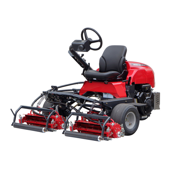
Baroness LM315GC Owner's Operating Manual
Riding greens mower (gasoline model)
Hide thumbs
Also See for LM315GC:
- Service manual (199 pages) ,
- Owner's operating manual (115 pages) ,
- Assembly and installation manual (19 pages)

Related Manuals for Baroness LM315GC


Summary of Contents for Baroness LM315GC
- Page 1 Riding Greens Mower (Gasoline Model) Owner's Operating Manual Serial No. LM315GC:30727- "Required reading" Read this manual and the Owner's Manual for the engine before using the machine. Ver.3.1...
- Page 2 LM315GC Regulations California Proposition65 WARNING: Operating, servicing and maintaining a passenger vehicle or off-road vehicle can expose you to chemicals including engine exhaust, carbon monoxide, phthalates, and lead, which are known to the State of California to cause cancer and birth defects or other reproductive harm.
- Page 3 LM315GC Greeting Thank you for purchasing the Baroness machine. This manual explains proper handling, adjustment, and inspection of your machine. Prior to use, carefully read this manual to thoroughly understand the contents for safe and correct operation. We hope you will use the machine safely, and take advantage of its best performance.
- Page 4 The information described in this manual is subject to change for improvement without prior notice. When replacing parts, be sure to use genuine Baroness parts or parts designated by Kyoeisha. Note that the Baroness product warranty may not apply to defects caused by the use of parts from other companies.
- Page 5 LM315GC Introduction Purpose For greens/for tees: This machine is intended for cutting turf grass at golf courses. For fields: This machine is intended for cutting turf grass on soccer and baseball fields. Do not use this machine in any other way than its intended purpose, and do not modify the machine.
- Page 6 LM315GC Introduction...
-
Page 7: Table Of Contents
LM315GC Contents Safety .............. Page 1-1 Safe Operating Practices .......Page 1-2 Disposal ............Page 2-1 Waste Disposal ..........Page 2-2 Product Overview .......... Page 3-1 Specifications ..........Page 3-2 Names of Each Section ......... Page 3-4 Safety Signs and Instruction Signs ....Page 3-5 Handling Instructions ........ - Page 8 LM315GC Contents...
-
Page 9: Safety
LM315GC Safety Safe Operating Practices ...... Page 1-2 Training ..........Page 1-2 Preparation ..........Page 1-2 Operation ..........Page 1-3 Maintenance and storage ...... Page 1-4 Page 1-1... -
Page 10: Safe Operating Practices
LM315GC Safety Failure to adequately follow these safety Incorrect hitching and load distribution precautions may cause an accident resulting in Never allow children or people unfamiliar injury or death. with these instructions to use or service the machine. Danger Danger... - Page 11 LM315GC Safety Check that operator's presence controls, Do not change the engine governor settings safety switches and shields are attached and or overspeed the engine. Operating the functioning properly. Do not operate unless engine at excessive speed may increase the they are functioning properly.
- Page 12 LM315GC Safety Take care when loading or unloading the Never allow untrained personnel to service machine into a trailer or a truck. Load or machine. unload the machine in a flat and safe place. Allow the engine/muffler to cool before Before loading or unloading, set the parking checking/maintenance.
- Page 13 LM315GC Safety Charge batteries in an open well ventilated area, away from spark and flames. Unplug charger before connecting or disconnecting from battery. Wear protective clothing and use insulated tools. Keep all parts in good working condition and all hardware tightened. Replace all worn or damaged decals.
- Page 14 LM315GC Safety Page 1-6 Safe Operating Practices...
-
Page 15: Disposal
LM315GC Disposal Waste Disposal ........Page 2-2 About the Waste disposal ...... Page 2-2 Page 2-1... -
Page 16: Waste Disposal
LM315GC Disposal Waste Disposal About the Waste disposal Make sure that waste generated when servicing or repairing the machine is disposed of in accordance with local regulations. (e.g. waste oil, antifreeze batteries, rubber products, and wires etc.) Page 2-2 Waste Disposal... -
Page 17: Product Overview
LM315GC Product Overview Specifications ........Page 3-2 Specifications .........Page 3-2 Names of Each Section ......Page 3-4 Serial Number Plate .......Page 3-4 ROPS Authentication Decal ....Page 3-4 Evaporative Emissions Control Plate ..Page 3-4 Safety Signs and Instruction Signs ..Page 3-5 About Safety Signs and Instruction Signs ............Page 3-5... -
Page 18: Specifications
LM315GC Product Overview Specifications Specifications Model LM315GC (for greens) LM315GC (for tees) LM315GC (for fields) Total length 84.65 in 215 cm 84.65 in 215 cm 84.65 in 215 cm Dimensio Total width 79.92 in 203 cm 79.92 in 203 cm 79.92 in... - Page 19 LM315GC Product Overview Speed Reverse model : 0 - model : 0 - model : 0 - model : 0 - model : 0 - model : 0 - (HST) 5.59 mph] 9.0 km/h] 5.59 mph] 9.0 km/h] 5.59 mph]...
-
Page 20: Names Of Each Section
LM315GC Product Overview Serial Number Plate Names of Each Section The serial number plate indicates the model and serial number of the machine. 4ogipb-001 Serial Number Plate_001 ROPS Authentication Decal The ROPS authentication decal indicates the manufacturer, model, etc., in accordance with International Standard ISO 21299:2009. -
Page 21: Safety Signs And Instruction Signs
6iul4h-066 Positions of Safety Decals and Instruction Decals_001 Part numbers for decals that need to be replaced are listed in the parts catalog. Order them from a Baroness dealer or Kyoeisha. Safety Signs and Instruction Signs Page 3-5... -
Page 22: Safety Signs And Instruction Signs
LM315GC Product Overview Description of Safety Decals and Instruction Decals ( - #30726) LM315GC0407Z0 Decal, operating gasoline type Warning Read the Owner's Operating Manual. Warning Apply the parking brake, stop the engine, remove the ignition key, and then leave the machine. - Page 23 LM315GC Product Overview K4209000980 Hydraulic oil icon Read the Owner's Operating Manual. K 4 2 0 9 0 0 0 9 8 0 qigqnx-020 K4209001310 Decal, lead-free gasoline Use lead-free gasoline. qigqnx-040 K4205001920 Decal for caution to hot parts Caution High temperature - Do not touch.
- Page 24 LM315GC Product Overview Danger Danger Flying objects - All persons other than the operator must keep a safe distance from the machine. qigqnx-060 K4205001560 Decal, read Owner's Operating Manual Warning Read the Owner's Operating Manual. qigqnx-017 K4205001710 Decal, caution for ROPS Replace a damaged ROPS.
-
Page 25: Handling Instructions
LM315GC Handling Instructions Inspection Before Use ......Page 4-2 Mower Pedal ........Page 4-28 Mower Unit Up Switch ......Page 4-29 Reel Cutter (Cutting Cylinder) and 2WD/3WD Selector Switch ....Page 4-30 Bed Knife (Bottom Blade) ...... Page 4-2 Reel Rotation Switch ......Page 4-31 Hydraulic Oil .......... -
Page 26: Inspection Before Use
LM315GC Handling Instructions Make sure that the oil level is at the middle Inspection Before Use of the oil gauge. Be sure to perform an inspection before you start using the machine so that you will be able to take advantage of its optimum performance for a long period of time. - Page 27 LM315GC Handling Instructions Move forward and reverse repeatedly Wind new sealing tape on the drain plug, several times. and then attach it to the hydraulic tank. Raise the mower units and maintain that position on a level surface, and then check to see if the oil level is at the middle of the oil gauge.
-
Page 28: Air Cleaner
LM315GC Handling Instructions Air Cleaner Pre-cleaner Air cleaner element Inspection of Air Cleaner Cover For details on handling the engine, please Knob refer to the separate Engine Handling Manual. Plate The air cleaner is a component that removes Remove the clip, and then remove the dirt from the intake air to prevent wear of the cover. -
Page 29: Battery
LM315GC Handling Instructions Even if the hours of operation do not Supply of Battery Fluid exceed the specified time, change it at least once per year. For details on handling the battery, please refer to the Battery's Owner's Manual. Replace the air cleaner element in the same manner as cleaning the air cleaner. -
Page 30: Tire
LM315GC Handling Instructions Make sure that there are no cracks, Tire damage or abnormal wear. Inspection of Tires Wire Check the pneumatic pressure of the tires. Inspection of Wire Make sure that there are no cracks, Make sure that the wire is not cracked or damage or abnormal wear. - Page 31 LM315GC Handling Instructions Replace the oil filler cap. Oil level gauge Oil filling port The appropriate oil level should be between the upper and lower limit lines on the gauge. bgmiun-011 Filling of Engine Oil_001 Oil level gauge Oil filling port...
-
Page 32: Fuel
LM315GC Handling Instructions Move the machine onto a level surface, Fuel stop the engine, remove the drain plug while the engine oil is warm, and then drain Inspection of Fuel Quantity the oil into a bowl. With the machine on a level surface, observe... -
Page 33: Oil Leakage
LM315GC Handling Instructions If the fuel gauge, located on the fuel tank, indicates a level close to E (EMPTY), supply fuel (gasoline) at your earliest convenience. The fuel tank capacity is approximately 20.0 (20.0 L). 2e4emp-003 Fuel Supply_001 Fuel tank... -
Page 34: Tightening Torques
LM315GC Handling Instructions Tightening torques Standard tightening torques Bolts and Nuts Important A number of bolts are used in each part of this machine. Be sure to re-tighten the bolts and nuts, because they may be loosened at the earlier stage of the use. - Page 35 LM315GC Handling Instructions Heat-treated bolt Strength classification 8.8 Strength classification 10.9 Nominal diameter 10.9 tib3yb-002 tib3yb-003 kgf-cm lb-in kgf-cm lb-in 5 - 7 50.99 - 71.38 44.26 - 61.96 7 - 10 71.38 - 101.97 61.96 - 88.51 8 - 11 81.58 - 112.17...
-
Page 36: Principal Tightening Torques
LM315GC Handling Instructions Principal tightening torques Tightening Torque by Model LM315GC Tighten the following bolts and nuts at the torque specified in the table. For thread locking adhesive, apply a middle strength thread locker (ThreeBond 1322 or equivalent anaerobic sealant). - Page 37 LM315GC Handling Instructions Tightening torque Thread Location Code Part name locking kgf-cm lb-in adhesive 1835.46 - 1593.18 - Wheel K0010100302 Bolt, heat-treated M10-30 45 - 57 2039.40 1770.20 1835.46 - 1593.18 - Brake drum K0010100302 Bolt, heat-treated M10-30 45 - 57 2039.40...
-
Page 38: Adjustment Before Operating
LM315GC Handling Instructions Adjustment of Steering Wheel Adjustment Before Operating Adjustment of Seat Warning Use the seat adjustment levers to adjust the Since it is dangerous, do not adjust the seat. steering wheel while traveling. Adjust the position according to the operator's body size. -
Page 39: Adjustment Of Blade Engagement
LM315GC Handling Instructions The steering wheel angle can be adjusted up Reel reverse lever or down. Adjust the position according to the operator's Adjust the engagement between the reel cutter body size. (cutting cylinder) and the bed knife (bottom Pull the angle adjustment lever, position the... -
Page 40: Adjustment Of Cutting Height
LM315GC Handling Instructions LM315GC (for tee mowing) Adjustment of Cutting Height You can adjust the rear roller by eight stages. Adjust the cutting height to fit your cutting work. Attach the rear roller in a position that Important suits your work requirements within the This applies the set cutting height that differs cutting height range. - Page 41 LM315GC Handling Instructions LM315GC (for field mowing) Adjustment of Front Roller You can adjust the rear roller by eight stages. Set the slide caliper to the required cutting height, adjust the neck position of the Attach the rear roller in a position that...
-
Page 42: Adjustment Of Groomer
LM315GC Handling Instructions Adjust the front roller up and down by the Set the groomer screw of the cutting height roller adjuster to determine the position of gauge to the desired height. the front roller, in order not to have a gap... - Page 43 LM315GC Handling Instructions Adjust the groomer adjuster so that the groomer screw can contact with the cutting edge of the groomer. Place the cutting height gauge set to the desired height on the ends of the front and rear rollers.
-
Page 44: Cutting Height And Blade Thickness Of Bed Knife (Bottom Blade)
LM315GC Handling Instructions Cutting Height and Blade Thickness of Bed Knife (Bottom Blade) Important The recommended minimum cutting heights are based on those of common greens. They may vary according to the green conditions and machine specifications. If the green undulation is hard, set it a little bit higher in order not to damage the green surface. -
Page 45: Procedure To Start / Stop Engine
LM315GC Handling Instructions Adjustment of Cutter Adjustment Spring If the diameter of the reel cutter (cutting cylinder) becomes smaller, adjust the cutter adjustment spring. Adjust the blade engagement. Loosen the pipe with cutter adjusting screw, and then adjust the length of the spring coil to approximately 26.0 mm (1.024 in). - Page 46 LM315GC Handling Instructions Make sure that the traveling pedal is in Check that the engine has started, and then neutral position. return the choke knob to its original position. Shift the throttle lever halfway from the turtle icon (low speed) to the rabbit icon Shift the throttle lever to the turtle icon (low (high speed) position.
-
Page 47: Operation Of Each Section
LM315GC Handling Instructions Safety Mechanisms Cautions for when You Leave the Machine This machine features a safety device for Caution starting/stopping the engine. If the brakes are not sufficiently effective, use As for starting the engine, the safety device the wheel stoppers to secure the machine. - Page 48 LM315GC Handling Instructions (#30346 - ) 6n6oux-027 Description about Operation Decals_003 Decal, reel rotation changeover 6n6oux-026 Description about Operation Decals_004 Decal, mower unit reel rotation changeover Page 4-24 Operation of Each Section...
- Page 49 LM315GC Handling Instructions ( - #30420) K4203001540 Decal, reel rotation/stop It illustrates Rotation/Stop of the reel cutter (cutting cylinder). 1.Rotate 2.Stop 6n6oux-028 (#30421 - ) TRAVEL Decal, reel rotation/stop It illustrates Rotation/Stop of the reel cutter (cutting cylinder). 1.Rotate 2.Stop...
- Page 50 LM315GC Handling Instructions (#30727 - ) Decal, mower unit up-switch(with reel excess discharge system) It illustrates the up-switch of the mower unit and the reel excess discharge system. 6n6oux-134 ( - #30420) K4203001530 Decal, 2WD/3WD changeover Note: Depending on the specifications, this function may not be available.
-
Page 51: Light Switch
LM315GC Handling Instructions LM315GC1418Z0 Decal, reel rotation changeover It illustrates the rotation changeover of the reel cutter (cutting cylinder) for High speed, Low speed and back lapping. 1.High 2.Low 6n6oux-035 3.Back lapping K4203001550 Decal, mower unit reel rotation changeover It illustrates the rotation changeover of the reel cutter (attached to the mower unit) for Normal rotation, Neutral and Reverse rotation. -
Page 52: Throttle Lever
LM315GC Handling Instructions Throttle Lever Mower Pedal The throttle lever is located in the operation Caution panel and enables you to adjust the engine rpm. Do not keep depressing the mower pedal after Move the throttle lever toward the rabbit icon an operation. -
Page 53: Mower Unit Up Switch
LM315GC Handling Instructions When it is switched to the down position, the Reel excess discharge system ・ green LED on the steering column lights up. Reel refreshing is the function to remove The Up/Down speed of the mower unit is clippings inside the reel cutter by rotating affected by the engine rotation speed. -
Page 54: 2Wd/3Wd Selector Switch
LM315GC Handling Instructions ( - #30420) Important When the reel rotation switch is set to the "MOW" (reel rotation) position, regardless of the position of the 2WD/3WD selector switch, 3WD is selected. When the traveling mode is switched to 3WD, the red LED in front of the 2WD/3WD selector switch lights up. -
Page 55: Reel Rotation Switch
LM315GC Handling Instructions (#30421 - ) Reel Rotation Switch The reel rotation switch is located in the operation panel. Setting the switch to the Warning "MOW" (reel rotation) position rotates the reel, and to the "TRAVEL" (reel stop) Set the reel rotation switch to the "TRAVEL"... -
Page 56: Reel Reverse Lever
Important For the LM315GC (for fields), normally cut with the lever set to the "L" position. The transmission selector lever is located at the upper part of the transmission, behind the driver's seat. -
Page 57: Traveling Pedal
LM315GC Handling Instructions Traveling Pedal Parking Brake Lever Warning Caution This machine is not authorized as a special Be sure to release the parking brake before motor vehicle. Do not drive it on public roads. driving. Otherwise, it may cause the malfunction of the brake or hydraulic system. -
Page 58: Instruments
LM315GC Handling Instructions When closing the underseat cover, do it slowly and be sure to use the forward tilt angle adjustment lever to fix it securely. Instruments Instruments on the Operation Panel ( - #30420) i5jb7e-012 Hood_001 Hood When closing the hood, do the operation slowly. -
Page 59: Travel Of Machine
LM315GC Handling Instructions Hour meter Travel of Machine The hour meter is located in the operation Moving the Machine panel, and indicates the accumulated operation time of the engine. Warning The number in black figures on a white Set the reel rotation switch to the "TRAVEL"... -
Page 60: Cutting Work
LM315GC Handling Instructions Cutting Work Caution Before restarting the engine, be sure to close Cutting Work the unload valve. Warning Stop the engine. "Procedure to Stop Engine" (Page 4-22) Do NOT start to move or stop the machine abruptly. Apply the parking brake and chock the To do so is very dangerous. -
Page 61: Reel Refreshing Operation
LM315GC Handling Instructions Start the work following the procedure below. Preventing lumps of clippings from falling ・ onto the green. Depress the traveling pedal. Use reel excess discharge system so that Depress the mower pedal when the the clippings inside the reel cutter can be... -
Page 62: Transporting
LM315GC Handling Instructions Removing Grass Catcher To discard the collected grasses, set the reel rotation switch to the "TRAVEL" (reel stop) position. Lower the mower unit. Apply the parking brake. Stop the engine. Lift up the grass catcher and remove it. -
Page 63: Maintenance
LM315GC Maintenance Maintenance Precautions ..... Page 5-2 Maintenance Schedule ......Page 5-3 Specified Values ........Page 5-5 Main Consumable Parts ......Page 5-6 Jacking up the machine ......Page 5-7 About the Jacking up the machine ..Page 5-7 Jack-up Points ........Page 5-7 Greasing .......... -
Page 64: Maintenance Precautions
Use tools appropriate for each maintenance operation. Caution For the safe and best performance of your machine, use Baroness genuine parts for replacement and accessories. Please note that our product warranty may be void if you use non-genuine parts for replacement or accessories. -
Page 65: Maintenance Schedule
LM315GC Maintenance Maintenance Schedule LM315GC (Gasoline Model) Follow the maintenance schedule below. ○・・・Inspect, adjust, supply, clean ●・・・Replace (first time) △・・・Replace Maintenance Item Tightening the parts ○ Fuel ○... - Page 66 LM315GC Maintenance Maintenance Item Greasing (center part of ○ the flexible wire) Refer to Greasing (main body "greasing point" ○ ...
-
Page 67: Specified Values
(16.0 L) Engine oil capacity Summer: SAE30, Winter: SAE20 1.6 dm (1.6 L) (including oil filter) LM315GC (For green/For field) 80 kPa (0.8 kgf/㎝ Smooth 18 x 9.50-8 2P Front tire pneumatic pressure LM315GC (For teeing ground) 100 kPa (1.0 kgf/㎝... -
Page 68: Main Consumable Parts
LM315GC Maintenance Main Consumable Parts Part name Code Engine oil filter PL842921 Air cleaner element PL272490S (Outer element) Air cleaner filter K2740000010 (Inner element) Fuel filter PL845125 Spark plug PL792015 Fuse K3631000040 Hydraulic suction filter K3413000050 Hydraulic cartridge filter K3412000050... -
Page 69: Jacking Up The Machine
LM315GC Maintenance Jacking up the machine Front right frame Front left frame About the Jacking up the machine Engine mount frame Front right frame Warning When replacing a tire or beginning any other maintenance or repairs, be sure to chock the wheels to prevent the machine from moving. -
Page 70: Greasing
LM315GC Maintenance Greasing No. of Location greasing About Greasing points Mower unit Since there may be adhesion or damage due Mower arm fulcrum to lack of grease on moving parts, they must be greased. Belt tension lever Add urea-based No. 2 grease in accordance Neutral position area with the Maintenance Schedule. - Page 71 LM315GC Maintenance Mower arm fulcrum Neutral position area Front mower unit There are two greasing points on each mower unit. 8bq62b-155 Greasing Points_007 Rear wheel pivot 8bq62b-167 Greasing Points_004 Rear mower unit There are two locations. 8bq62b-156 Greasing Points_008 Mower pedal shaft fulcrum...
- Page 72 LM315GC Maintenance Traveling pedal shaft fulcrum Flexible wire Use Moly speed grease No.2 Screw in the grease cup 360 degrees and add grease. Central part Add grease every 8 hours of operation. 8bq62b-160 Greasing Points_011 Rear wheel brake lever shaft...
-
Page 73: Maintenance (Mower)
Maintenance Have the following items ready: Strips of Maintenance (Mower) newspaper, Abrasive [Back lapping powder mixed with oil; or gel compound (Baroness Back Lapping of Reel Cutter (Cutting genuine abrasive)], Brush. Cylinder) Back lapping is work similar to sharpening a cooking knife. -
Page 74: Adjusting Cam
LM315GC Maintenance Check the sharpness of the entire range Adjusting CAM (three or four points from the left edge to the right one) of the reel cutter (cutting cylinder). When the gap at the left frame side between the reel cutter (cutting cylinder) and the bed Using a piece of chalk, mark locations on the knife (bottom blade) appears. -
Page 75: Maintenance (Main Body)
LM315GC Maintenance Reel cutter (Cutting cylinder) Bearing Bed knife (Bottom blade) Seal Lock nut Reel cutter (Cutting cylinder) Cam bush Inner nut Max 0.3 mm (0.012 inch) Outer nut Bed knife (bottom blade) moving up Bed knife (bottom blade) moving down... - Page 76 LM315GC Maintenance Remove the bolts. Caution Refer to the Tightening Torque Table. Note that the Baroness product warranty may not apply to defects caused by incorrect or overtorque tightening etc. Important Tighten the bolts in the tightening order (crosswise). 75uxaw-005...
-
Page 77: Adjustment Of Belt Tension
Remove the tire from the wheel mounting in the middle of pulleys. base. Caution Refer to the Tightening Torque Table. Note that the Baroness product warranty may not apply to defects caused by incorrect or overtorque tightening etc. Important Tighten the bolts in the tightening order (crosswise). -
Page 78: Adjustment Of Parking Brake
LM315GC Maintenance Press the middle of the belt with your finger Adjust the parking brake by tightening the to check the belt tension. brake wire adjustment bolt. ulabms-003 i352yo-001 Engine Tension Belt_001 Adjustment of Parking Brake_001 Engine tension belt Parking brake lever... -
Page 79: Adjusting The Neutral Position Of The Piston Pump
LM315GC Maintenance Once the adjustment has completed, be Caution sure to lock with the nut. When adjusting the neutral position, pay close attention to abrupt start of the machine. Place the jacks beneath the jack-up points, and then lift the machine until all the tires get off the ground. -
Page 80: Grease Change Of Transmission
LM315GC Maintenance Grease Change of Transmission The transmission is located behind the driver's seat. Change grease every two years. Grease type Pyronoc CC1 Grease quantity 400 g 7syu5e-002 Fuses_001 Main harness fuse Light harness fuse Check the Operation Status of the Relay Mower Unit Control Relay The relay box is located behind the seat. -
Page 81: Long-Term Storage
LM315GC Maintenance Removal of Mower Unit Interlock Relay The relay box is located under the underseat Remove the clip which fixes the mower unit cover. and flexible wire. This controls a safety device for starting/ stopping the engine. The operating condition can be checked by the illumination of the LEDs. - Page 82 LM315GC Maintenance Page 5-20 Long-Term Storage...
- Page 83 Turf Care Machinery Head Office : 1-26,Miyuki-cho,Toyokawa,Aichi-Pref., 442-8530 Japan. Tel : 81-533-84-1095 Fax : 81-533-84-1225 U.S. and CALIFORNIA EVAPORATIVE EMISSION CONTROL WARRANTY STATEMENT The United States Environmental Protection Agency (EPA), the California Air Resources Board (CARB) and KYOEISHA CO.,LTD are pleased to explain the evaporative emission control system’s warranty on your 2018 model year equipment.
- Page 84 You are responsible for presenting your equipment to a KYOEISHA U.S.A. INC or authorized service dealer as soon as the problem exists. The warranty repairs shall be completed in a reasonable amount of time, not to exceed 30 days. If you have a question regarding your warranty coverage, you should contact a...
- Page 85 Any warranted part that is scheduled for replacement as required maintenance in owner’s operating manual supplied is warranted for the period of time before the first scheduled replacement date for that part. If the part fails during the period of warranty coverage, repair or replacement of any warranted part under the warranty provisions herein must be performed at KYOEISHA CO.,LTD at no charge to the owner.
- Page 86 Head Office 1-26, Miyuki-cho, Toyokawa, Tel : (0533) 84 - 1390 Aichi-Pref. 442-8530 Japan. Fax : (0533) 89 - 3623 LM315GC-UMB-USZ/17K-00-S.K 201801[LM315GC_EV2018AA01]...
Need help?
Do you have a question about the LM315GC and is the answer not in the manual?
Questions and answers