
Related Manuals for Mitsubishi RV-2F Series


Summary of Contents for Mitsubishi RV-2F Series
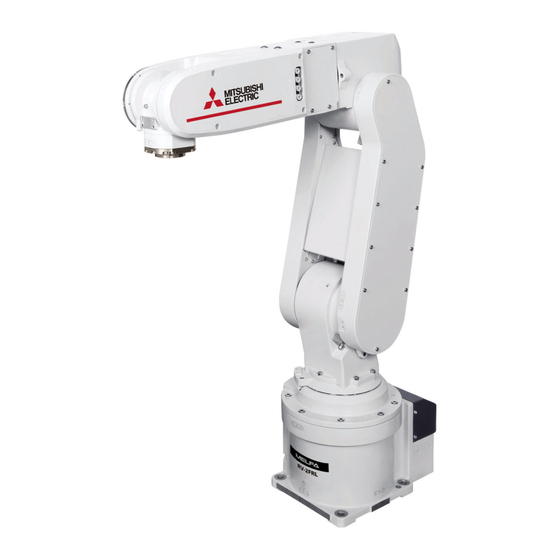
- Page 1 Mitsubishi Industrial Robot RV-2F Series INSTRUCTION MANUAL ROBOT ARM SETUP & MAINTENANCE BFP-A8904-C...
- Page 3 Safety Precautions Always read the following precautions and the separate "Safety Manual" before starting use of the robot to learn the required measures to be taken. CAUTION All teaching work must be carried out by an operator who has received special training.
- Page 4 The points of the precautions given in the separate "Safety Manual" are given below. Refer to the actual "Safety Manual" for details. CAUTION Use the robot within the environment given in the specifications. Failure to do so could lead to a drop or reliability or faults. (Temperature, humidity, atmosphere, noise environment, etc.) CAUTION Transport the robot with the designated transportation posture.
- Page 5 CR751-D or CR751-Q because of leakage protection. AC200V Earth leakage breaker 漏電遮断器 (NV) CR751-D controller/CR751-Q drive unit CR751コントローラ(前面) Cover 端子カバー Note) RV-2F series has operation panel. Grounding Connector コネクタ アース接続ネジ screw Cover 端子カバー Grounding terminal 保護アース端子...
- Page 6 Revision history Date of Point Instruction Manual No. Revision Details 2012-06-21 BFP-A8904 ・ First print 2012-10-03 BFP-A8904-A ・The movement direction of the joint jog and 3-axis XYZ jog of the J5 axis was corrected (error in writing). ・ The notes about installation of the controller and the robot arm were added. (neither direct rays nor the heat of lighting) 2012-11-19 BFP-A8904-B...
- Page 7 This document explains for the following robot type. Robot type ・ RV-2F series (The specification in which all axes have the brake is included.) ・ No part of this manual may be reproduced by any means or in any form, without prior consent from Mitsubishi.
-
Page 8: Table Of Contents
CONTENTS Page 1 Before starting use .......................... 1-1 1.1 Using the instruction manuals ....................1-1 1.1.1 The details of each instruction manuals ................1-1 1.1.2 Symbols used in instruction manual ..................1-2 1.2 Safety Precautions ........................1-3 1.2.1 Precautions given in the separate Safety Manual ..............1-4 2 Unpacking to Installation ................................ - Page 9 CONTENTS Page (5) Inspection, maintenance and replacement of J4-axis timing belt ............5-56 (6) Inspection, maintenance and replacement of J5 axis timing belt and brake timing belt ..... 5-57 (7) Inspection, maintenance and replacement of J6-axis timing belt and brake timing belt .... 5-60 (8) Timing belt tension ..............................
-
Page 10: Before Starting Use
1Before starting use 1 Before starting use This chapter explains the details and usage methods of the instruction manuals, the basic terminology and the safety precautions. 1.1 Using the instruction manuals 1.1.1 The details of each instruction manuals The contents and purposes of the documents enclosed with this product are shown below. Use these doc- uments according to the application. -
Page 11: Symbols Used In Instruction Manual
1Before starting use 1.1.2 Symbols used in instruction manual The symbols and expressions shown in Table 1-1 are used throughout this instruction manual. Learn the meaning of these symbols before reading this instruction manual. Table 1-1:Symbols in instruction manual Terminology Item/Symbol Meaning iQ Platform... -
Page 12: Safety Precautions
1Before starting use 1.2 Safety Precautions Always read the following precautions and the separate "Safety Manual" before starting use of the robot to learn the required measures to be taken. CAUTION All teaching work must be carried out by an operator who has received special training. -
Page 13: Precautions Given In The Separate Safety Manual
1Before starting use 1.2.1 Precautions given in the separate Safety Manual The points of the precautions given in the separate "Safety Manual" are given below. Refer to the actual "Safety Manual" for details. DANGER If the automatic operation of the robot is operated by two or more control equip- ment, design the right management of operation of each equipment of the cus- tomer. - Page 14 1Before starting use CAUTION Do not stop the robot or apply emergency stop by turning the robot controller's main power OFF. If the robot controller main power is turned OFF during automatic operation, the robot accuracy could be adversely affected. CAUTION Do not turn off the main power to the robot controller while rewriting the internal information of the robot controller such as the program or parameters.
-
Page 15: Unpacking To Installation
Users who have purchased optional products should refer to the separate "Standard Specifications". Table 2-1 : Standard configuration Part name Type Qty. Remarks Robot arm RV-2F series 1 unit Guarantee card 1 copy Installation bolts M8x35 4 pcs. Spring washer for installation bolts For M8 4 pcs. -
Page 16: Installation
2Unpacking to Installation 2.2 Installation 2.2.1 Unpacking (a) Topples over (b) Pull out (slowly) (d) Take out ④ (c) Raise CAUTION Always unpack the robot at a flat place. The robot could tilt over if unpacked at an Notes) The packing material is required at re-transportation. unstable place. -
Page 17: Transportation Procedures(Transportation By People)
2Unpacking to Installation 2.2.2 Transportation procedures(Transportation by people) Mass: Approx. 21kg No.2 arm Fixing plate Elbow CAUTION 注意 VORSICHT Fixing plate Lower section of elbow(B) Flange of base(A) Base Fig.2-2 : Transportation of robot arm (Transportation by people) 1) The robot be transported by one worker. Place the robot on a dolly, etc. and move it to the vicinity of the installation site. -
Page 18: Installation Procedures
2Unpacking to Installation 2.2.3 Installation procedures The installation procedure of the robot arm is shown below. 1) The robot installation surface has been machine finished. Use the installation holes (4-φ9 holes) opened at the four corners of the base, and securely fix the robot with the enclosed installation bolts (M8 x 35 hexagon socket bolts). -
Page 19: Grounding Procedures
2Unpacking to Installation 2.2.4 Grounding procedures (1) Grounding methods 1) There are three grounding methods as shown in Fig. 2-4, but the dedicated grounding (Fig. 2-4 (a)) should be used for the robot arm and controller when possible. (Refer to the separate " Controller Controller Controller Controller... -
Page 20: Connecting With The Controller
2Unpacking to Installation 2.2.5 Connecting with the controller (1) CR750 controller Motor power Motor signal モータパワー モータ信号 Robot arm ロボット本体 (CN2) (CN1) (ベース部背面) Opposite side of figure Controller (Rear side) Connection ring 接続リング部 Connection latch ラッチ (fixing) (固定) (固定用 左右) (For fixing. Right and left) Connection ring 接続リング部... -
Page 21: Cr751 Controller
2Unpacking to Installation (2) CR751 controller Robot arm ロボット本体 Motor signal (CN2) モータ信号(CN2) Motor power モータ電源 (ベース部背面) Opposite side of figure AMP1 AMP2 BRK Controller Two fixing screws Connection ring 接続リング部 Connection latch (fixing) ラッチ (固定) Motor signal cable モータ信号ケーブル (For fixing. -
Page 22: Setting The Origin
2Unpacking to Installation 2.3 Setting the origin The origin is set so that the robot can be used with a high accuracy. After purchasing the robot, always carry out this step before starting work. This step must also be carried out if the combination of robot and controller being used is changed. -
Page 23: Installing The T/B (Cr751 Controller)
2Unpacking to Installation (2) Installing the T/B (CR751 controller) Explain the installation method of T/B below. 1) Check that the POWER (power supply) switch of the robot controller is OFF. 2) Connect the T/B connector to the controller’s T/B connector. Make sure to fix it securely by fastening the hand locks (in 2 places), as shown in Fig. -
Page 24: Setting The Origin With The Origin Data Input Method
2Unpacking to Installation 2.3.2 Setting the origin with the origin data input method (1) Confirming the origin data ● Origin data history table (Origin Data History) Serial No.ES804008 The origin data to be input is noted in the Date Default . -
Page 25: Preparing The T/B
2Unpacking to Installation (3) Preparing the T/B Next, prepare to use the T/B 1) Set the mode of the controller to "MANUAL". (The figure is example for CR750 controller) MODE MANUAL AUTOMATIC 2) Set the T/B [ENABLE] switch to "ENABLE". The menu selection screen will appear. -
Page 26: Selecting The Origin Setting Method
2Unpacking to Installation (4) Selecting the origin setting method <MENU> 1) Press the [4] key on the menu screen, and display the 1.FILE/EDIT 2.RUN ORIGIN/BRAKE screen. 3.PARAM. 4.ORIGIN/BRK 5.SET/INIT. 6.ENHANCED CLOSE <ORIGIN/BRAKE> 2) Press the [1] key on the ORIGIN/BRAKE screen, and 1.ORIGIN 2.BRAKE display the origin setting method selection screen. -
Page 27: Inputting The Origin Data
2Unpacking to Installation (5) Inputting the origin data Origin data label T/B screen Input the value confirmed in section Page 15, "(1) (D,J1,J2,J3,J4,J5,J6,J7,J8) Confirming the origin data". The correspondence of the origin data label value and axis to <ORIGIN> DATA D:(■... -
Page 28: Installing The J1 Motor Cover
2Unpacking to Installation <ORIGIN> DATA 6) After inputting all of the values, press the [EXE] key. The D:( V!%S29) origin setting confirmation screen will appear. J1( 06DTYY) J2( 2?HL9X) J3( 1CP55V) J4( T6!MSY) J5( Z21J%Z) J6( A12%Z0) ) J8( CLOSE 7) Press [F1] (Yes) to end the origin setting <ORIGIN>... -
Page 29: Confirming The Operation
2 Unpacking to Installation 2.4 Confirming the operation In this section, the robot will be moved manually using the T/B to confirm that the operation is correct. Moving the robot manually is called "jog operation". This operation includes the JOINT jog that moves each axis, the XYZ jog that moves along the base coordinate system, the TOOL jog that moves along the tool coordinate system, and the CYLNDER jog that moves along the circular arc. - Page 30 2 Unpacking to Installation +Z - + +Z + - +X - +Y + Control point 制御点 * While maintaining the flange surface posture, the -Y -X axis moves straight along the base coordinate system. Also, while maintaining the flange ※...
- Page 31 2 Unpacking to Installation J4 axis +Z J5 axis J6 axis * The axis moves straight along the base coordinate system. At this time, the flange -Y surface posture is not maintained. Also, the -X flange surface posture changes. The flange surface position does not change at this time.
- Page 32 2 Unpacking to Installation Tool - length + + Control point - 制御点 * While maintaining the flange surface posture, the axis moves straight - along the work coordinate system. + Also, while maintaining the flange surface position, the flange surface WORK coordinate system ワー...
-
Page 33: Joint Jog Operation
2 Unpacking to Installation (1) JOINT jog operation Select joint jog mode [JOG] Press the key and display the jog screen. ("JOG" is displayed on the screen bottom) <CURRENT> JOINT 100% M1 T0 Check that the "joint" in jog mode is displayed on +0.00 +0.00 the screen. - Page 34 2 Unpacking to Installation J2 axis jog operation ・ When the [+Y (J2)] keys are pressed, the J2 axis will rotate in the plus direction. When the [-Y (J2)] keys are pressed, Rotate in the minus direction. ◇◆◇ When the robot is in the transportation posture ◇◆◇ The axes may be outside the movement area.
- Page 35 2 Unpacking to Installation J4, J5 and J6 axis jog operation + - J4 axis J4軸 J5 axis J5軸 + - + - J6 axis J6軸 ・ When the [+A (J4)] keys are pressed, the J4 axis will rotate in the plus direction. When the [-A (J4)] keys are pressed, Rotate in the minus direction.
-
Page 36: Xyz Jog Operation
2 Unpacking to Installation (2) XYZ jog operation Select XYZ jog mode [JOG] Press the key and display the jog screen. ("JOG" is displayed on the screen bottom) <CURRENT> JOINT 100% M1 T0 Check that the "XYZ" in jog mode is displayed on +0.00 +0.00 the screen. - Page 37 2 Unpacking to Installation ◇◆◇If the buzzer of T/B sounds and the robot does not move ◇◆◇ If it is going to move the robot across the operation range, the buzzer of T/B sounds and the robot does not move. In this case, please move to the counter direction. Changing the flange surface posture +Z -...
-
Page 38: Tool Jog Operation
2 Unpacking to Installation (3) TOOL jog operation Select TOOL jog mode [JOG] Press the key and display the jog screen. ("JOG" is displayed on the screen bottom) <CURRENT> JOINT 100% M1 T0 Check that the "TOOL" in jog mode is displayed +0.00 +0.00 on the screen. - Page 39 2 Unpacking to Installation ◇◆◇If the buzzer of T/B sounds and the robot does not move ◇◆◇ If it is going to move the robot across the operation range, the buzzer of T/B sounds and the robot does not move. In this case, please move to the counter direction. Changing the flange surface posture +Z +Y...
-
Page 40: 3-Axis Xyz Jog Operation
2 Unpacking to Installation (4) 3-axis XYZ jog operation Select XYZ456 jog mode [JOG] Press the key and display the jog screen. ("JOG" is displayed on the screen bottom) <CURRENT> JOINT 100% M1 T0 Check that the "XYZ456" in jog mode is +0.00 +0.00 displayed on the screen. - Page 41 2 Unpacking to Installation Changing the flange surface posture + - J4 axis J4軸 J5 axis J5軸 + - + - J6 axis J6軸 * The wrist pose can be changed maintaining the flange's position. ・ When the[+A (J4)] keys are pressed, the J4-axis will rotate in the plus direction. At this time, to maintain the flange's position, other axes move simultaneously except J5 and J6.
-
Page 42: Cylnder Jog Operation
2 Unpacking to Installation jog operation CYLNDER Select cylindrical jog mode [JOG] Press the key and display the jog screen. ("JOG" is displayed on the screen bottom) <CURRENT> JOINT 100% M1 T0 Check that the "CYLNDER" in jog mode is +0.00 +0.00 displayed on the screen. - Page 43 2 Unpacking to Installation Changing the flange surface posture +Z - + +Z + - +X +Y - + -Y -X * The flange position does not change. This is the same as the A, B and C axis XYZ jog operation.
-
Page 44: Work Jog Operation
2 Unpacking to Installation (6) Work jog operation Setting of the work coordinates system is necessary. By this jog operation, robot can be move along with the direction of work (or working table etc.), so teaching operations get easier. When jog operation, select by which work coordinates the robot moves The setting method of the work coordinates system using T/B (R32TB) is shown in the following.... - Page 45 2 Unpacking to Installation 2) Press the [2] keys in the menu screen and select "2. WORK COORD." <EMHANCED> <WORK COORD> WORK NUMBER (1) TEACHING POINT (WO) 1.SQ DIRECT 2.WORK COORD. X: 0.00 Y: 0.00 Z: 0.00 123 TEACH ...
- Page 46 2 Unpacking to Installation Presses the function key corresponding to"Yes", the robot's current position is registered, and the registered coordinates value is displaye. Operation will be canceled if the [CLOSE] key is pressed. <WORK COORD> WORK NUMBER (2) <WORK COORD> WORK NUMBER (2) TEACHING POINT (WO) TEACHING POINT (WO)
- Page 47 2 Unpacking to Installation Although setting of work coordinates is finishing above, confirmation of work coordinates can be done by press - ing the function key corresponding to "W GRID."([F2]) <WORK COORD> WORK NUMBER (2) <WORK COORD> WORK NUMBER (2) TEACHING POINT (WO) WORK COORDINATES DATA X: 214.12...
- Page 48 2 Unpacking to Installation The jog movement based on work coordinates system Tool length Controll point 制御点 * The direction of the flange will not change. Move the control point with a straight line in accordance with the work coordinates system Work coordinates system ・...
- Page 49 2 Unpacking to Installation Changing the flange surface posture - Tool length + + Controll 制御点 - point - * The position of the control point + -Y -X does not change. Change the Work coordinates system direction of the flange in accordance with the work coordinates system.
-
Page 50: Installing The Option Devices
3Installing the option devices 3 Installing the option devices 3.1 Installing the solenoid valve set The installation summary of the solenoid valve is shown in Fig. 3-1. Turn the controller’s power OFF before this installing operation. Refer to Page 49, "5.3.2 Installing/removing the cover" for removing/ installing the cover. - Page 51 3Installing the option devices 3) Connect the AIR IN "1" mark secondary piping coupler to the A port <4> of the No. 1 solenoid valve <3> with an air hose (φ4 approx. 250mm, prepared by customer.) In the same manner, connect the AIR IN "2" mark secondary piping coupler to the B port 5 of the No. 1 solenoid valve.
-
Page 52: Basic Operations
4Basic operations 4 Basic operations The basic operations from creating the program to automatic operation are explained in section "4. Basic operations" in the "From Controller Setup to Maintenance" manual. Refer that manual as necessary. 4-43... -
Page 53: Maintenance And Inspection
5Maintenance and Inspection 5 Maintenance and Inspection The maintenance and inspection procedures to be carried out to use the robot for a long time without trouble are described in this chapter. The types and replacement methods of consumable parts are also explained. 5.1 Maintenance and inspection interval Maintenance and inspection are divided into the inspections carried out daily, and the periodic inspections carry out at set intervals. -
Page 54: Inspection Items
5Maintenance and Inspection 5.2 Inspection items The inspection items for the robot arm are shown below. Also refer to section "5. Maintenance and inspection" in the "Controller setup, basic operation, and maintenance" manual, and inspect the controller. 5.2.1 Daily inspection items Carry out the daily inspections with the procedures given in Table 5-1. -
Page 55: Periodic Inspection
5Maintenance and Inspection 5.2.2 Periodic inspection Carry out periodic inspection with the procedures given in Table 5-2. Table 5-2 : Periodic inspection items (details) Procedure Inspection item (details) Remedies Monthly inspection items Are any of the bolts or screws on the robot arm loose? Securely tighten the bolts. -
Page 56: Maintenance And Inspection Procedures
The procedures for carrying out the periodic maintenance and inspection are described in this section. Thoroughly read the contents, and follow the instructions. This work can be commissioned to the Mitsubishi Service Depart - ment for a fee. (Never disassemble, etc., the parts not described in this manual.) The maintenance parts, etc., required for the customer to carry out maintenance and inspection are described in... - Page 57 5Maintenance and Inspection <13>J5 axis motor <15>J5 axis timing belt for brake <10>J4 axis motor <11> Timing belt <14> Timing belt <16> Reduction gears <21> Reduction gears <17>J5 axis brake <12> Reduction gears <20>Gear <23>J6 axis brake <18>J6 axis motor <19>...
-
Page 58: Installing/Removing The Cover
5Maintenance and Inspection 5.3.2 Installing/removing the cover 6. Elbow cover R 5. Elbow cover B 8. No.2 arm cover R 7. No.2 arm cover L 4. No.1 arm cover L 3. No.1 arm cover R 1. Battery cover 2. J1 motor cover 9. - Page 59 5Maintenance and Inspection Table 5-3 : Cover names Cover names Installation screw <1> Battery cover 1 Bind screw M3 Four <2> J1 motor cover 1 Bind screw M3 Four <3> No. 1 arm cover R 1 Bind screw M3 Four <4>...
-
Page 60: Inspection, Maintenance And Replacement Of Timing Belt
5 Maintenance and Inspection 5.3.3 Inspection, maintenance and replacement of timing belt This robot uses a timing belt for the drive conveyance system of the J5 axis. Compared to gears and chains, the timing belt does not require lubrication and has a low noise. However, if the belt usage method and tension adjust - ment are inadequate, the life could drop and noise could be generated. -
Page 61: Inspection, Maintenance And Replacement Of J1-Axis Timing Belt
5 Maintenance and Inspection (2) Inspection, maintenance and replacement of J1-axis timing belt The reference figure at inspection, adjustment, and replacement of the timing belt is shown in Fig. 5-4 <3>Tension adjustment screw With the fixing nut <1>Motor plate fixing screw <6>Motor plate hook Pulls and fixing <4>Timing pulley (near side) - Page 62 5 Maintenance and Inspection <3>Tension adjustment screw <4>. Timing pulley With the fixing nut <1>Motor plate fixing screw <1>Motor plate fixing screw <6>Motor plate Mark <2>. Timing belt <5>. Timing pulley Inside of the bottom plate of robot arm (bottom) Fig.5-5 :...
-
Page 63: Inspection, Maintenance And Replacement Of J2-Axis Timing Belt
5 Maintenance and Inspection (3) Inspection, maintenance and replacement of J2-axis timing belt The reference figure at inspection, adjustment, and replacement of the timing belt is shown in Fig. 5-6. <3>Tension adjustment screw With the fixing nut <1> Idler inatallation screw Idler J2 axis <4>... -
Page 64: Inspection, Maintenance And Replacement Of J3-Axis Timing Belt
5 Maintenance and Inspection (4) Inspection, maintenance and replacement of J3-axis timing belt The reference figure at inspection, adjustment, and replacement of the timing belt is shown in Fig. 5-7. <3>Tension adjustment screw <1> Idler installation screw With the fixing nut Mark Mark Idler... -
Page 65: Inspection, Maintenance And Replacement Of J4-Axis Timing Belt
5 Maintenance and Inspection (5) Inspection, maintenance and replacement of J4-axis timing belt The reference figure at inspection, adjustment, and replacement of the timing belt is shown in Fig. 5-8. <1>Motor plate fixing screw Mark <3>Tension adjustment screw With the fixing nut Mark J3 axis <4>... -
Page 66: Inspection, Maintenance And Replacement Of J5 Axis Timing Belt And Brake Timing Belt
5 Maintenance and Inspection (6) Inspection, maintenance and replacement of J5 axis timing belt and brake timing belt The J5 axis has the timing belt rotating the J5 axis and the brake timing belt conveying the brake. The inspection, maintenance and replacement method of each belt is shown below. A)Inspection, maintenance and replacement of J5-axis timing belt The reference figure at inspection, adjustment, and replacement of the timing belt is shown in Fig. - Page 67 5 Maintenance and Inspection 9) The position could deviate after the belt is replaced. Confirm that the position has not deviated. If deviated, refer to Page 70, "5.6 Resetting the origin", and reset the origin position. B)Inspection, maintenance and replacement of J5 axis brake timing belt The reference figure at inspection, adjustment, and replacement of the brake timing belt is shown in Fig.
- Page 68 5 Maintenance and Inspection ■ Replacing the J5 axis brake timing belt 1) Carry out steps 1) and 2) indicated in " ■ Inspecting the J5 axis brake timing belt" above. 2) Remove J5 axis timing belt with referring to above "...
-
Page 69: Inspection, Maintenance And Replacement Of J6-Axis Timing Belt And Brake Timing Belt
5 Maintenance and Inspection (7) Inspection, maintenance and replacement of J6-axis timing belt and brake timing belt The reference figure at inspection, adjustment, and replacement of the timing belt is shown in Fig. 5-11. In the RV-2SDB the J6 axis has the timing belt rotating the J6 axis and the brake timing belt conveying the brake. Also inspection, maintenance and replace the brake timing belt simultaneously. - Page 70 5 Maintenance and Inspection 9) The position could deviate after the belt is replaced. Confirm that the position has not deviated. If deviated, refer to Page 70, "5.6 Resetting the origin", and reset the origin position. B)Inspection, maintenance and replacement of J6 axis brake timing belt The reference figure at inspection, adjustment, and replacement of the brake timing belt is shown in Fig.
- Page 71 5 Maintenance and Inspection ■ Replacing the J6 axis brake timing belt 1) Carry out steps 1) and 2) indicated in " ■ Inspecting the J6 axis brake timing belt" above. 2) Remove J6 axis timing belt with referring to above "...
-
Page 72: Timing Belt Tension
5 Maintenance and Inspection (8) Timing belt tension f : Pressing force s : Span d : Slack T : Tension ■ The preset value and adjustment value in the sound wave type belt tension gauge Preset value Tension: Used belt (N) Tension: New belt (N) Force of pulling the Axis... -
Page 73: Lubrication
5 Maintenance and Inspection 5.3.4 Lubrication (1) Lubrication position and specifications The grease nipple position is shown in Fig. 5-14. The lubrication specifications for each place are shown in Table 5-4. Refer to the Page 49, "5.3.2 Installing/removing the cover" for the method of removing and installing the cover. -
Page 74: Lubrication Method
5 Maintenance and Inspection [Caution] ・ The brand name of the grease shown in the Table 5-4 is the grease put in at shipping. ・The lubrication time is a cumulative value of the operation at the maximum speed. If the operation has been sus - pended, or if the designated speed is slow, the lubrication time can be lengthened in proportion.(The "Lubrica - tion interval "... -
Page 75: Replacing The Backup Battery
5 Maintenance and Inspection 5.3.5 Replacing the backup battery An absolute encoder is used for the position detector, so while power of controller is turned off the position must be saved by the backup battery. The controller also uses a backup battery to save the program, etc. The battery is the lithium battery. -
Page 76: Replacing The Battery (Robot Arm)
5 Maintenance and Inspection (1) Replacing the battery (robot arm) CAUTION The power supply for the encoder is supplied by cable connected with battery board. The cable must be connected while replacing the battery or operating usually. Thus, if the cable connection is incomplete, the encoder position data will be lost, and reset - ting the origin is necessary. -
Page 77: About Overhaul
5 Maintenance and Inspection 5.4 About Overhaul Robots which have been in operation for an extended period of time can suffer from wear and other forms of deterioration. In regard to such robots, we define overhaul as an operation to replace parts running out of speci - fied service life or other parts which have been damaged, so that the robots may be put back in shape for contin - ued use. -
Page 78: Maintenance Parts
Timing belt J1 axis 1 J2 axis 1 J3 axis 1 J4axis 1 J5axis 1 Mitsubishi Electric System & Service;Co.,Ltd. For J5 axis brakes 1 J6 axis 1 Note1) 1 For J6 axis brakes Grease Reduction gears of each axis... -
Page 79: Resetting The Origin
5 Maintenance and Inspection 5.6 Resetting the origin The origin is set so that the robot can be used with a high accuracy. After purchasing the robot, always carry out this step before starting work. The origin must be reset if the combination of robot and controller being used is changed or if the motor is changed causing an encoder area. -
Page 80: Mechanical Stopper Method
5 Maintenance and Inspection 5.6.1 Mechanical stopper method The method for setting the origin with the transportation jig is explained below. This operation is carried out with the T/B. Set the controller mode to "MANUAL", and set the T/B [ENABLE] switch to "ENABLE"... - Page 81 5 Maintenance and Inspection <BRAKE> 7) Detach the [F1] key and work the brake. J1:( )J2:( )J3:( Press the [F4] key and return to the origin / J4:( )J5:( )J6:( J7:( )J8:( brake screen. REL. CLOSE <ORIGIN/BRAKE> 8) Press the [1] key, and display the Origin setting 1.ORIGIN 2.BRAKE selection screen.
-
Page 82: J2 Axis Origin Setting(Mechanical Stopper)
5 Maintenance and Inspection (2) J2 axis origin setting(mechanical stopper) <MENU> 1) Press the [4] key on the menu screen, and dis - play the Origin/BRK selection screen. 1.FILE/EDIT 2.RUN 3.PARAM. 4.ORIGIN/BRK 5.SET/INIT. 6.ENHANCED 123 CLOSE 2) Press the [2] key , and display the Break <ORIGIN/BRAKE>... - Page 83 5 Maintenance and Inspection <ORIGIN/BRAKE> 8) Press the [1] key, and display the Origin setting 1.ORIGIN 2.BRAKE selection screen. CLOSE <ORIGIN> 9) Press the [2] key, and display the Mechanical 1.DATA 2.MECH stopper selection screen. 3.TOOL 4.ABS 5.USER CLOSE <ORIGIN> MECH ~...
-
Page 84: J3 Axis Origin Setting(Mechanical Stopper)
5 Maintenance and Inspection (3) J3 axis origin setting(mechanical stopper) <MENU> 1) Press the [4] key on the menu screen, and dis - 1.FILE/EDIT 2.RUN play the Origin/BRK selection screen. 3.PARAM. 4.ORIGIN/BRK 5.SET/INIT. 6.ENHANCED 123 CLOSE 2) Press the [2] key , and display the Break <ORIGIN/BRAKE>... - Page 85 5 Maintenance and Inspection <ORIGIN/BRAKE> 8) Press the [1] key , and display the Origin setting 1.ORIGIN 2.BRAKE selection screen. CLOSE <ORIGIN> 9) Press the [2] key , and display the Mechanical 1.DATA 2.MECH stopper selection screen. 3.TOOL 4.ABS 5.USER CLOSE <ORIGIN>...
-
Page 86: J4 Axis Origin Setting(Mechanical Stopper)
5 Maintenance and Inspection (4) J4 axis origin setting(mechanical stopper) <MENU> 1) Press the [4] key on the menu screen, and dis - 1.FILE/EDIT 2.RUN play the Origin/BRK selection screen. 3.PARAM. 4.ORIGIN/BRK 5.SET/INIT. 6.ENHANCED 123 CLOSE 2) The type which does not have the brake in the J4 axis should go to 6->8. - Page 87 5 Maintenance and Inspection <ORIGIN> 9) Press the [2] key , and display the Mechanical 1.DATA 2.MECH stopper selection screen. 3.TOOL 4.ABS 5.USER CLOSE 10) Press the [Arrow] key, move the cursor to the <ORIGIN> MECH ~ J4 axis and press the [1] key. Set [0] to other axes.
-
Page 88: J5/J6 Axis Origin Setting(Mechanical Stopper)
5 Maintenance and Inspection (5) J5/J6 axis origin setting(mechanical stopper) Always perform origin setting of the J5 axis and the J6 axis simultaneously. First, set the J5 axis posture. <MENU> 1) Press the [4] key on the menu screen, and 1.FILE/EDIT 2.RUN display the Origin/BRK selection screen. - Page 89 5 Maintenance and Inspection Then, set the J6 axis posture. 8) Install the bolt (M5: 2 customer preparation) in the diagonal position at the J6 axis. ABS mark Hold the bolts with hands, rotate them slowly and align the ABS mark of the J6 axis with the ABS mark of the wrist area.
- Page 90 5 Maintenance and Inspection <ORIGIN> MECH ~ 16) Press the [Arrow] key, move the cursor, and set "1" to the J5 axis and J6 axis. Set [0] to other axes. SPACE CLOSE 17) Press the [EXE] key , and display Confirmation screen.
-
Page 91: Jig Method
5 Maintenance and Inspection 5.6.2 Jig method This method is using the origin setting tool. If the origin setting tool is required, please ask nearby dealer. The reference figure of the origin setting tool is shown in Fig. 5-17. RZ6.3 Fig.5-17 :... -
Page 92: J1 Axis Origin Setting
5 Maintenance and Inspection (1) J1 axis origin setting <MENU> 1) Press the [4] key on the menu screen, and dis - 1.FILE/EDIT 2.RUN play the Origin/Brake selection screen. 3.PARAM. 4.ORIGIN/BRK 5.SET/INIT. 6.ENHANCED 123 CLOSE Select ORIGIN/BRK <ORIGIN/BRAKE>... - Page 93 5 Maintenance and Inspection <ORIGIN/BRAKE> 8) Press the [1] key, and display the Origin setting 1.ORIGIN 2.BRAKE selection screen. CLOSE <ORIGIN> 9) Press the [3] key, and display the Tool selection 1.DATA 2.MECH screen. 3.TOOL 4.ABS 5.USER CLOSE Select TOOL ...
-
Page 94: J2 Axis Origin Setting
5 Maintenance and Inspection (2) J2 axis origin setting <MENU> 1) Press the [4] key on the menu screen, and dis - 1.FILE/EDIT 2.RUN play the Origin/Brake selection screen. 3.PARAM. 4.ORIGIN/BRK 5.SET/INIT. 6.ENHANCED 123 CLOSE <ORIGIN/BRAKE> 2) Press the [2] key, and display the Brake release 1.ORIGIN 2.BRAKE selection screen. - Page 95 5 Maintenance and Inspection <BRAKE> 8) Detach the [F1] key and work the brake. Press the [F4] key and return to the origin / J1:( )J2:( )J3:( J4:( )J5:( )J6:( brake screen. J7:( )J8:( REL. CLOSE <ORIGIN/BRAKE> 9) Press the [1] key, and display the Origin setting 1.ORIGIN 2.BRAKE selection screen.
-
Page 96: J3 Axis Origin Setting
5 Maintenance and Inspection (3) J3 axis origin setting <MENU> 1) Press the [4] key on the menu screen, and dis - 1.FILE/EDIT 2.RUN play the Origin/Brake selection screen. 3.PARAM. 4.ORIGIN/BRK 5.SET/INIT. 6.ENHANCED 123 CLOSE <ORIGIN/BRAKE> 2) Press the [2] key, and display the Brake release 1.ORIGIN 2.BRAKE selection screen. - Page 97 5 Maintenance and Inspection <BRAKE> 8) Detach the [F1] key and work the brake. Press the [F4] key and return to the origin / J1:( )J2:( )J3:( J4:( )J5:( )J6:( brake screen. J7:( )J8:( REL. CLOSE <ORIGIN/BRAKE> 9) Press the [1] key, and display the Origin setting 1.ORIGIN 2.BRAKE selection screen.
-
Page 98: J4 Axis Origin Setting
5 Maintenance and Inspection (4) J4 axis origin setting <MENU> 1) Press the [4] key on the menu screen, and dis - 1.FILE/EDIT 2.RUN play the Origin/Brake selection screen. 3.PARAM. 4.ORIGIN/BRK 5.SET/INIT. 6.ENHANCED 123 CLOSE <ORIGIN/BRAKE> 2) The type which does not have the brake in the 1.ORIGIN 2.BRAKE J4 axis should go to "7)"->"9)". - Page 99 5 Maintenance and Inspection <ORIGIN/BRAKE> 9) Press the [1] key, and display the Origin setting 1.ORIGIN 2.BRAKE selection screen. CLOSE <ORIGIN> 10) Press the [3] key, and display the Tool selec - 1.DATA 2.MECH tion screen. 3.TOOL 4.ABS 5.USER CLOSE <TOOL>...
-
Page 100: Origin Setting Of J5 Axis And J6 Axis (Jig)
5 Maintenance and Inspection (5) Origin setting of J5 axis and J6 axis (jig) Always perform origin setting of the J5 axis and the J6 axis simultaneously. First, set the J5 axis posture. <MENU> 1) Remove the No.2 arm cover B. The pin hole is 1.FILE/EDIT 2.RUN inside the cover. - Page 101 5 Maintenance and Inspection <BRAKE> 9) Detach the [F1] key and work the brake. J1:( )J2:( )J3:( J4:( )J5:( )J6:( J7:( )J8:( REL. CLOSE Next, set the J6 axis posture. 10) Install the bolt (M5: 2, customer preparation) in the diagonal position at the J6 axis. Hold the bolts with hands, rotate them slowly ABS mark and align the ABS mark of the J6 axis with the...
- Page 102 5 Maintenance and Inspection <ORIGIN/BRAKE> 16) Press the [1] key , and display the Origin 1.ORIGIN 2.BRAKE setting selection screen. CLOSE 17) Press the [3] key , and display the Tool <ORIGIN> selection screen. 1.DATA 2.MECH 3.TOOL 4.ABS 5.USER CLOSE 18) Press the [Arrow] key, move the cursor, and set "1"...
-
Page 103: Abs Origin Method
5 Maintenance and Inspection 5.6.3 ABS origin method When the origin setting of the robot is performed for the first time, this product records the angular position of the origin within one rotation of the encoder as the offset value. If the origin setting is performed according to the ABS origin method, this value is used to suppress variations in the origin setting operations and to reproduce the initial origin position accurately. -
Page 104: Select The T/B
5 Maintenance and Inspection The procedures for setting the origin with the ABS method are explained below. (1) Select the T/B Do the following operations with pressing the enabling switch of T/B lightly. <MENU> 1) Press the [4] key on the menu screen, and dis - 1.FILE/EDIT 2.RUN play the Origin/Brake selection screen. -
Page 105: User Origin Method
5 Maintenance and Inspection 5.6.4 User origin method CAUTION Before using this method, the origin must be set with the other method. The setting method is explained in Page 70, "Table 5-8 : Origin setting method". The procedure for setting the origin with the user origin method is explained below. This operation is carried out with the teaching pendant. - Page 106 5 Maintenance and Inspection <USER> 8) Input "1" into the axis to origin setting. Press J1:( )J2:( )J3:( the [EXE] key, and display Confirmation screen. J4:( )J5:( )J6:( ~ J7:( )J8:( REL. CLOSE → 9) Press the [F1] key, and the origin position is set <ORIGIN>...
-
Page 107: Recording The Origin Data
5 Maintenance and Inspection 5.6.5 Recording the origin data When the origin has been set with the jig method, record that origin data on the origin data label. With this, the ori - gin can be set with the origin data input method the next time. Confirm the origin data on the teaching pendant screen (origin data input screen). -
Page 108: 6Appendix
6Appendix 6 Appendix Appendix 1 : Configuration flag The configuration flag indicates the robot posture. For the 6-axis type robot, the robot hand end is saved with the position data configured of X, Y, Z, A, B and C. However, even with the same position data, there are several postures that the robot can change to. The posture is expressed by this configuration flag, and the posture is saved with FL1 in the position constant (X, Y, Z, A, B, C) (FL1, FL2). - Page 109 6Appendix (3) NONFLIP/FLIP This means in which side the J6 axis is in comparison with the plane through both the J4 and the J5 axis. J4 axis FL1 (Flag 1) FLIP &B0000 0000 ↑ 1/0=NONFLIP/FLIP Note) "&B" is shows the binary NON FILIP J6 axis flange surface Fig.6-3 :...
- Page 110 6Appendix Configuration flag Appendix-101...
- Page 111 HEAD OFFICE: TOKYO BUILDING, 2-7-3, MARUNOUCHI, CHIYODA-KU, TOKYO 100-8310, JAPAN NAGOYA WORKS: 5-1-14, YADA-MINAMI, HIGASHI-KU, NAGOYA 461-8670, JAPAN Authorised representative: MITSUBISHI ELECTRIC EUROPE B.V. GERMANY Gothaer Str. 8, 40880 Ratingen / P.O. Box 1548, 40835 Ratingen, Germany Dec., 2012 MEE Printed in Japan on recycled paper.
- Page 112 Phone: +1 847 478 21 00 Fax: +1 847 478 22 53 Mitsubishi Electric Europe B.V. /// FA - European Business Group /// Gothaer Straße 8 /// D-40880 Ratingen /// Germany Tel.: +49(0)2102-4860 /// Fax: +49(0)2102-4861120 /// info@mitsubishi-automation.com /// www.mitsubishi-automation.com...
Need help?
Do you have a question about the RV-2F Series and is the answer not in the manual?
Questions and answers