
Related Manuals for Mitsubishi MELFA RV-100TH


Summary of Contents for Mitsubishi MELFA RV-100TH
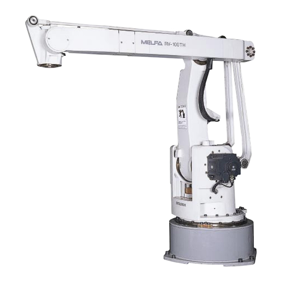
- Page 1 MITSUBISHI Mitsubishi Industrial Robot RV-100TH/150TH RV-100THL/150THL INSTRUCTION MANUAL ROBOT ARM SETUP & MAINTENANCE BFP-A8038-A...
-
Page 2: Safety Precautions
Safety Precautions Always read the following precautions and the separate "Safety Manual" before starting use of the robot to learn the required measures to be taken. CAUTION All teaching work must be carried out by an operator who has received special training. (This also applies to maintenance work with the power source turned ON.) →... - Page 3 The points of the precautions given in the separate "Safety Manual" are given below. Refer to the actual "Safety Manual" for details. CAUTION Use the robot within the environment given in the specifications. Failure to do so could lead to a drop or reliability or faults. (Temperature, humidity, atmosphere, noise environ - ment, etc.) CAUTION Transport the robot with the designated transportation posture.
-
Page 4: Revision History
Revision history Date of Point Instruction Manual No. Revision Details 2000-11-27 BFP-A8038Z First print. 2001-01-15 BFP-A8038 Formal style. 2001-03-21 BFP-A8038-A Error in writing correction. - Page 5 ■ Introduction Thank you for purchasing the Mitsubishi industrial robot. This instruction manual explains procedures to be taken for unpacking, installing, servicing and inspecting the robot arm. Always read through this manual before starting use to ensure correct usage of the robot.
-
Page 6: Table Of Contents
Contents Page 1 Before starting use ..................................1-1 1.1 Using the instruction manuals ............................1-1 1.1.1 The details of each instruction manuals ........................ 1-1 1.1.2 Symbols used in instruction manual ........................1-2 1.2 Safety Precautions ................................. 1-3 1.2.1 Precautions given in the separate Safety Manual ..................... 1-4 2 Unpacking to Installation ................................ - Page 7 Page...
-
Page 8: Before Starting Use
1Before starting use 1 Before starting use This chapter explains the details and usage methods of the instruction manuals, the basic terminology and the safety precautions. 1.1 Using the instruction manuals 1.1.1 The details of each instruction manuals The contents and purposes of the documents enclosed with this product are shown below. Use these documents according to the application. -
Page 9: Symbols Used In Instruction Manual
1Before starting use 1.1.2 Symbols used in instruction manual The symbols and expressions shown in Table 1-1 are used throughout this User's Manual. Learn the meaning of these symbols before reading this instruction manual. Table 1-1 : Symbols in instruction manual Symbol Meaning Precaution indicating cases where there is a risk of operator fatality or seri -... -
Page 10: Safety Precautions
1Before starting use 1.2 Safety Precautions Always read the following precautions and the separate "Safety Manual" before starting use of the robot to learn the required measures to be taken. CAUTION All teaching work must be carried out by an operator who has received special training. (This also applies to maintenance work with the power source turned ON.) →... -
Page 11: Precautions Given In The Separate Safety Manual
1Before starting use 1.2.1 Precautions given in the separate Safety Manual The points of the precautions given in the separate "Safety Manual" are given below. Refer to the actual "Safety Manual" for details. CAUTION Use the robot within the environment given in the specifications. Failure to do so could lead to a drop or reliability or faults. -
Page 12: Unpacking To Installation
2Unpacking to Installation 2 Unpacking to Installation 2.1 Confirming the product The standard configuration of the robot arm section, part of the purchased product, is shown in Table 2-1. Confirm the parts. Users who have purchased optional products should refer to the separate "Standard Specifications". Table 2-1 :... -
Page 13: Installation
2Unpacking to Installation 2.2 Installation 2.2.1 Unpacking The robot is packaged in a wooden crate when shipped. Unpack the robot from the crate. Handle the robot arm following the section "2.2.2Transportation procedures" in this manual. (1) Remove the wood crate for transporting the robot arm. (2) Remove the hexagon nuts fixing the wood crate base and robot arm. -
Page 14: Transportation Procedures
2Unpacking to Installation 2.2.2 Transportation procedures 1) Transport the robot in the packaged state to the unpacking place when possible. 2) Unpack the robot. 3) Lift the robot with a rope passed through the eyebolts, and transport it in a suspended state to the site of installation. - Page 15 2Unpacking to Installation 1502 1502 1502 1502 2092 2092 2092 2092 1108 1108 1108 1108 RV-100THL/150TH L Fig.2-2 : Transportation posture (RV-100THL/150THL) 2-8 Installation...
- Page 16 2Unpacking to Installation (2) Transporting with a crane ■ RV-100TH Catch two wires into the M30 eye bolts, and suspend the robot. After installing, remove the eye bolts. RV-100T RV-100T RV-100T RV-100TH H H H J2=+30 deg. J2=+30 deg. , , , , J3=+90 deg. J2=+30 deg.
- Page 17 2Unpacking to Installation ■ RV-150TH Catch two wires into the M30 eye bolts, and suspend the robot. After installing, remove the eye bolts. RV-15 5 5 5 0T RV-1 0TH H H H RV-1 RV-1 J2=+30 deg. J2=+30 deg. J2=+30 deg. J2=+30 deg.
- Page 18 2Unpacking to Installation ■ RV-100THL/150THL Catch two wires into the M30 eye bolts, and suspend the robot. After installing, remove the eye bolts RV-100THL/150T RV-100THL/150THL RV-100THL/150T RV-100THL/150T J2=+23 deg. ,J3=+63 deg. J2=+23 deg. , J3=+63 deg. J2=+23 deg. , J2=+23 deg. , J3=+63 deg.
- Page 19 2Unpacking to Installation (3) Transport method using a forklift ■ RV-100TH Transport by inserting the fork of the lift into the transport fittings (optional). RV-100T RV-100T RV-100T RV-100TH H H H Transportation posture: J2=+30 deg. ,J3=+90 deg. Robot arm mass: 960kg Transportation tools (optional) Fork width...
- Page 20 2Unpacking to Installation ■ RV-150TH Insert the fork of the forklift into the transportation jig (option) and transport the robot. RV-1 RV-1 RV-1 RV-15 5 5 5 0T 0TH H H H J2=+30 deg. ,J3=+75 deg. Transportation posture: 1100kg Robot arm mass: Transportation tools (optional) Fork width...
- Page 21 2Unpacking to Installation ■ RV-100THL/150THL Insert the fork of the forklift into the transportation jig (option) and transport the robot. RV-100THL/150T RV-100THL/150THL RV-100THL/150T RV-100THL/150T Transportation posture: J2=+23 deg. ,J3=+63 deg. Robot arm mass RV-100THL:1470kg RV-150THL:1520kg Transportation tools (optional) Fork width 1502 2092 1108...
-
Page 22: Installation Procedures
2Unpacking to Installation 2.2.3 Installation procedures (1) Installation reference Maintaining the optimum functions of the robot is the most important point of installing the robot arm. In respect to the robot arm fixing and foundation, to maintain the path accuracy while withstanding the weight applied on the arm and the reaction during movement, the robot arm must be fixed with sufficient force so that it does not move. - Page 23 2Unpacking to Installation 1000 9- φ28 hole for RV-150TH/THL/100THL Anchor bolt (M20) Nut (M20) Base plate Thickness of plate 32mm (Steel board) Fig.2-10 : Base plate using 2-16 Installation...
- Page 24 2Unpacking to Installation ■ Mechanical anchor execution method 1) Base material of install position above the base plate : Punch a hole of φ21.5 x 135 to concrete to set the anchor. 2) Insert a metal hit anchor MH-20190 (by Japan drive nut Inc.) with the threaded section protruding from the top face of the nut.
- Page 25 2Unpacking to Installation ■ Chemical anchor execution method 1) Base material of install position : Punch a hole of φ24 x 200 to concrete to set the anchor, then clean the inside of the hole using a jet of air, etc. 2) Insert an R-19 resin capsule (by Japan Decoluxe Inc.).
- Page 26 2Unpacking to Installation ■ The force given to the installation surface during operation To install the robot arm in the raised position, ensure that the raising base offers strength sufficient to withstand the following forces. The parallelism of the installation surface shall be 1 mm/m or less. Table 2-2 :...
-
Page 27: Grounding Procedures
2Unpacking to Installation 2.2.4 Grounding procedures (1) Grounding methods 1) There are three grounding methods as shown in Fig. 2-14 3, but the dedicated grounding (Fig. 2-14 (a)) should be used for the robot arm and controller Controller Controller Controller Controller Controller Controller... -
Page 28: Connecting With The Controller
2Unpacking to Installation 2.2.5 Connecting with the controller Controller Controller Controller Controller RV-100TH/150TH RV-100TH/150TH RV-100TH/150TH RV-100TH/150TH Robot arm Robot arm Robot arm Robot arm CN1 1 1 1 Earth Earth Earth Earth Motor signal cable Motor signal cable Motor signal cable Motor signal cable ( ( ( ( 7 7 7 7 m) m) m) -
Page 29: Setting The Origin
2Unpacking to Installation 2.3 Setting the origin The origin is set so that the robot can be used with a high accuracy. After purchasing the robot, always carry out this step before starting work. This step must also be carried out if the combination of robot and controller being used is changed. -
Page 30: Setting The Origin With The Origin Data Input Method
2Unpacking to Installation 2.3.2 Setting the origin with the origin data input method (1) Confirming the origin data ● Origin data history table (Origin Data History) Serial No.ES804008 The origin data to be input is noted in the Date Default . -
Page 31: Preparing The T/B
2Unpacking to Installation (3) Preparing the T/B Next, prepare to use the T/B. EMG.STOP STATUS NUMBER CHANG DISP 1) Set the [MODE] switch on the front of the controller to "TEACH". MODE SVO ON START RESET TEACH AUTO AUTO (Op.) (Ext.) REMOVE T/B SVO OFF... -
Page 32: Selecting The Origin Setting Method
2Unpacking to Installation (4) Selecting the origin setting method <T/B screen> [Keys used] <MENU> 1) Press the [5] key on the menu screen, and display the maintenance screen. 1.TEACH 2.RUN 3.FILE 4.MONI (J6) 5.MAINT 6.SET <MAINT> 1.PARAM 2.INIT 2) Press the [4] key on the maintenance screen, and display the origin setting 3.BRAKE 4.ORIGIN method selection screen. -
Page 33: Inputting The Origin Data
2Unpacking to Installation (5) Inputting the origin data Input the value confirmed in section "(1) Confirming the origin Origin data label data" on page T/B screen (D,J1,J2,J3,J4,J5,J6) The correspondence of the origin data label value and axis to be <DATA> D( D ) input is shown in Fig. -
Page 34: Moving The Cursor
2Unpacking to Installation ◇◆◇ Moving the cursor ◇◆◇ Press the [ ↑ ], [ ↓ ], [ ← ] and [ → ] keys. ◇◆◇ Inputting characters ◇◆◇ Hold down the [CHAR] key and press the key with the character to be input on the lower right. Three characters will scroll each time the character key is pressed. -
Page 35: Confirming The Operation
2Unpacking to Installation 2.4 Confirming the operation In this section, the robot will be moved manually using the T/B to confirm that the operation is correct. Moving the robot manually is called "jog operation". This operation includes the JOINT jog that moves each axis, the XYZ jog that moves along the base coordinate system, the TOOL jog that moves along the tool coordinate system, and the CYLNDER jog that moves along the circular arc. - Page 36 2Unpacking to Installation * While maintaining the flange surface posture, the axis moves straight along the base coordinate system. Also, while maintaining the flange surface position, the flange surface posture changes. Fig.2-21 : XYZ jog operation Origins of tool coordinates * While maintaining the flange surface posture, the axis moves straight along the tool coordinate system.
- Page 37 2Unpacking to Installation * The axis moves straight along the base Origins of base coordinates coordinate system. At this time, the flange surface posture is not maintained. Also, the flange surface posture changes. The flange surface position change at this time. Fig.2-23 :...
-
Page 38: Joint Jog Operation
2Unpacking to Installation (1) JOINT jog operation Select the JOINT jog mode Press the [MOVE] + [JOINT] keys to select the JOINT JOINT jog mode. "JOINT" will appear at the upper +34.50 JOINT left of the screen. STEP + +20.00 MOVE ( )? +80.00... - Page 39 2Unpacking to Installation J3 axis jog operation STEP + (J3) MOVE When the [MOVE] + [+Z (J3)] keys are pressed, the + + + + J3 axis will rotate in the plus direction. J3axis J3axis J3axis J3axis When the [MOVE] + [-Z (J3)] keys are pressed, the J3 axis will rotate in the minus direction.
-
Page 40: Xyz Jog Operation
2Unpacking to Installation (2) XYZ jog operation Select the XYZ jog mode Press the [MOVE] + [XYZ] keys to select the X +134.50 XYZ jog mode. "XYZ" will appear at the STEP Y +220.00 + upper left of the screen. MOVE Z +280.00 $":... -
Page 41: Tool Length
2Unpacking to Installation Changing the flange surface posture * Rotating around the Z axis When the [MOVE] + [+C (J6)] keys are pressed, the Z axis will rotate in the plus direction. When the [MOVE] + [-C (J6)] keys are pressed, the Z axis will rotate in the minus direction. -
Page 42: Tool Jog Operation
2Unpacking to Installation (3) TOOL jog operation Select the TOOL jog mode Press the [MOVE] + [TOOL] keys to select the TOOL TOOL jog mode. "TOOL" will appear at the upper X +134.50 left of the screen. TOOL STEP Y +220.00 +... - Page 43 2Unpacking to Installation Changing the flange surface posture * Rotating around the Z axis When the [MOVE] + [+C (J6)] keys are pressed, the Z axis will rotate in the plus direction of the tool coordinate system. When the [MOVE] + [-C (J6)] keys are pressed, the Z axis will rotate in the minus - - - - + + + +...
-
Page 44: 3-Axis Xyz Jog Operation
2Unpacking to Installation (4) 3-axis XYZ jog operation Select the 3-axis XYZ jog mode XYZ456 Press the [MOVE] + [XYZ] keys, and then X +134.50 press only the [XYZ] key. "XYZ456" will appear STEP Y +220.00 + at the upper left of the screen. MOVE Z +280.00 $":... - Page 45 2Unpacking to Installation Changing the flange surface posture When the [MOVE]+[+C(J6)] keys are pressed, the J4 axis will rotate in the plus direction. When the [MOVE]+[-C(J6)] keys are pressed, the - - - - + + + + J4 axis will rotate in the minus direction. J4 J4 STEP STEP...
-
Page 46: Cylnder Jog Operation
2Unpacking to Installation jog operation CYLNDER Select the cylindrical jog mode CYLNDER Press the [MOVE] + [XYZ] keys, and then press R +134.50 only the [XYZ] key. "CYLNDER" will appear at the STEP T +220.00 + upper left of the screen. MOVE Z +280.00 $":... - Page 47 2Unpacking to Installation Changing the flange surface posture +Z +Z * Rotating around the Z axis When the [MOVE] + [+C (J6)] keys are pressed, the Z axis will rotate in the plus direction. When the [MOVE] + [-C (J6)] keys are - - - - + + + + pressed, the Z axis will rotate in the minus...
-
Page 48: Installation Of Optional Equipment
3Installation of optional equipment 3 Installation of optional equipment 3.1 Procedure for pneumatic piping Fig. 3-1 shows the position of pneumatic pipe installation, while Fig. 3-2 shows 3-unit air supply device (optional). A single-circuit air-exhaust port is located at the edge of the No. 2 arm on the upper section. The air-supply port, which connects to the aforementioned exhaust port, is located at the rear of the base. - Page 49 3Installation of optional equipment Air panel assembly Details of air panel assembly Filter regulator + Lubulicator Residual pressure release valve Pressure switch Port diameter for pipe connection on the input side Rc(PT)3/8 Silencer Fig.3-2 : 3-unit air supply device 3-42 Procedure for pneumatic piping...
-
Page 50: Changes In The Operating Range
3Installation of optional equipment 3.2 Changes in the operating range When used at the customer's site, the operating range can be restricted to ensure safety, as in the avoidance of interference with surrounding devices. The operating range can be changed independently on the + (plus) and - (minus) sides. Make changes by changing the stopper positions and the parameter (MEJAR: joint operating range). - Page 51 3Installation of optional equipment 3-44 Changes in the operating range...
-
Page 52: Basic Operations
4Basic operations 4 Basic operations The basic operations from creating the program to automatic operation are explained in section "4. Basic operations" in the "From Controller Setup to Maintenance" manual. Refer that manual as necessary. 4-45... - Page 53 4Basic operations 4-46...
-
Page 54: Maintenance And Inspection
5Maintenance and Inspection 5 Maintenance and Inspection The maintenance and inspection procedures to be carried out to use the robot for a long time without trouble are described in this chapter. The types and replacement methods of consumable parts are also explained. 5.1 Maintenance and inspection interval Maintenance and inspection are divided into the inspections carried out daily, and the periodic inspections carry out at set intervals. -
Page 55: Inspection Items
5Maintenance and Inspection 5.2 Inspection items The inspection items for the robot arm are shown below. Also refer to section "5Maintenance and Inspection" in the "From Controller Setup to Maintenance" manual, and inspect the robot arm. 5.2.1 Daily inspection items Carry out the daily inspections with the procedures given in Table 5-1. -
Page 56: Periodic Inspection
Check and eliminate the cause. damage and adherence of foreign matter. If the cables are severely damaged, contact the Mitsubishi Service Department. Yearly inspection items Lubricate the grease at the harmonic reduction gears for each axis. Replace the backup battery in the robot arm. -
Page 57: Maintenance And Inspection Procedures
The procedures for carrying out the periodic maintenance and inspection are described in this section. Thoroughly read the contents, and follow the instructions. This work can be commissioned to the Mitsubishi Service Department for a fee. (Never disassemble, etc., the parts not described in this manual.) And, as for the exchange of the reduction gears, the robot must be return to the factory, or the customer prepare the lift device such as a chain block and working space. -
Page 58: Absolute Encoder
5Maintenance and Inspection (2) Drive mechanism of J2 axis The drive mechanism of J2 axis is shown in Fig. 5-3. J2 axis moves the No.1 arm forward and backward. The rotation of the AC servomotor is transmitted through the reduction gears to drive the No.1 arm. Here, the No.1 arm is supported with the reduction gears and bearing. - Page 59 5Maintenance and Inspection (3) Drive mechanism of J3 axis The drive mechanism of J3 axis is shown in Fig. 5-4. J3 axis moves the wrist joint up and down. The rotation of the AC servomotor is transmitted through the reduction gears to the lower link, back link and No.2 arm in order to move up and down the wrist joint installed at the No.2 arm tip.
-
Page 60: Motor Cover
5Maintenance and Inspection (4) Drive mechanism of J4 axis The drive mechanism of J4 axis is shown in Fig. 5-4. J4 axis turns the wrist flange and band. The rotation of the AC servomotor is transmitted through the reduction gears in order to turn the wrist flange and hand. -
Page 61: Lubrication
5Maintenance and Inspection 5.3.2 Lubrication 4 Reduction gears 2 3 Reduction gears Reduction gears 1 Reduction gears Turn spring Fig.5-6 : Grease and oil lubrication Table 5-3 : Grease and oil lubrication Lubrication position Grease and Oil Lubrication interval Amount (time) Axis Target part... - Page 62 5Maintenance and Inspection (1) Lubrication method of J1 axis section 1) Remove the oil plug attached to the turn axis, and fill new grease through that hole. 2) When the lubrication is finished, install the oil plug. CAUTION for the lubrication amounts. Exces - Follow the values given in Page 54, "Table 5-3"...
- Page 63 5Maintenance and Inspection (2) Lubrication method of J2,J3 axis section 1) Remove the oil plug, and fill new grease through that hole. 2) When the lubrication is finished, install the oil plug. CAUTION for the lubrication amounts. Exces - Follow the values given in Page 54, "Table 5-3"...
- Page 64 5Maintenance and Inspection (3) Lubrication method of J4 axis section 1) Remove the motor cover of the wrist joint. 2) Fill new grease through the grease nipple. 3) After the lubrication is finished, install the motor cover. 4) Pod the cable port of the motor cover with silicon sealant. CAUTION for the lubrication amounts.
-
Page 65: Retightening Procedure Of External Main Bolts
5Maintenance and Inspection 5.3.3 Retightening procedure of external main bolts. The positions of the bolts to be retightened are shown in Fig. 5-10. Depending on each model, retighten the bolts to the tightening torques shown in Table 5-4. (Before retightening each bolt, remove the cover, etc.) No.2 arm2 Cross roller bearing 9... -
Page 66: Replacing The Backup Battery
5Maintenance and Inspection 5.3.4 Replacing the backup battery An absolute encoder is used for the position detector, so the position must be saved with the backup battery when the power is turned OFF. The controller also uses a backup battery to save the program, etc. These batteries are installed when the robot is shipped from the factory, but as these are consumable parts, they must be replaced periodically by the user. -
Page 67: Maintenance Parts
Table 5-6. Purchase these parts from the dealer when required. Some Mitsubishi-designated parts differ from the maker's standard parts. Thus, confirm the part name, robot arm and controller serial No. and purchase the parts from the dealer. Since the types of 4-axes + puneumatic hose, 4-axes + puneumatic hose + servo hand, and 4-axes + two puneumatic hoses are separately shown in the table depending on the specifications of the robot arm, refer to the relevant part of the specifications. - Page 68 YR102A201G07 J4 axis (RV-150TH) Motor BU160A297G01 J1 axis BU160A297G02 J2 axis BU160A297G03 J3 axis BU160A297G04 J4 axis Mitsubishi Electric Reduction gears Note1 ) J1 axis YR103B513-01 Note1 ) J2 axis,J3 axis (RV-100TH) YR103B514-01 J2 axis,J3 axis (RV-150TH) Note1 ) YR103B514-02...
- Page 69 BU160A303G02 J2 axis BU160A303G03 J3 axis BU159C930G55 J4 axis Reduction gears Note1 ) J1 axis YR103B613-01 Mitsubishi Electric Note1 ) J2 axis,J3 axis (RV-100THL) YR103B609-01 Note1 ) J2 axis,J3 axis (RV-150THL) YR103B609-02 YR103B992-03 J4 axis (RV-100THL) YR103B992-04 J4 axis (RV-150THL)
- Page 70 BU160A303G02 J2 axis BU160A303G03 J3 axis BU159C930G55 J4 axis Reduction gears Note1 ) J1 axis YR103B613-01 Mitsubishi Electric Note1 ) J2 axis,J3 axis (RV-100THL) YR103B609-01 Note1 ) J2 axis,J3 axis (RV-150THL) YR103B609-02 YR102B992-03 J4 axis (RV-100THL) YR102B992-04 J4 axis (RV-150THL)
-
Page 71: Resetting The Origin
5Maintenance and Inspection 5.5 Resetting the origin The origin is set so that the robot can be used with a high accuracy. After purchasing the robot, always carry out this step before starting work. The origin must be reset if the combination of robot and controller being used is changed or if the motor is changed causing an encoder area. - Page 72 5Maintenance and Inspection Carry out the following operations while lightly holding down the deadman switch on the teaching pendant. <MENU> <MAINT> 1) Press the [5] key on the Menu screen to select 1.TEACH 2.RUN 1.PARAM 2.INIT the Maintenance screen. 3.FILE 4.MONI 3.BRAKE 4.ORIGIN 5.MAINT 6.SET...
-
Page 73: User Origin Method
5Maintenance and Inspection 5.5.2 User origin method The procedure for setting the origin with the user origin method is explained below. This operation is carried out with the teaching pendant. Set the [MODE] switch on the front of the controller to "TEACH", and set the [ENABLE/DISABLE] switch on the teaching pendant to "ENABLE"... - Page 74 5Maintenance and Inspection <JIG> 12345678 <JIG> BRAKE (00000000) CHANGES TO ORIGIN 9) Press the [1] key and then the [INP] key. The SET AXIS (11110000) OK?(1) origin will be set. ORIGIN :NOT DEF 1:EXECUTE → (J5) Set the origin This completes the setting of the origin with the user origin method.
- Page 75 5Maintenance and Inspection 5-68 Resetting the origin...
- Page 76 HEAD OFFICE : MITSUBISHI DENKI BLDG MARUNOUCHI TOKYO 100-8310 TELEX : J24532 CAB LE MELCO TOKYO NAGOYA WORKS : 1-14, YADA-MINAMI 5, HIGASHI-KU, NAGOYA, JAPAN MAR..2001 MEE Printed in Japan on recycled paper. Specifications are subject to change without notice.
Need help?
Do you have a question about the MELFA RV-100TH and is the answer not in the manual?
Questions and answers