
Subscribe to Our Youtube Channel
Related Manuals for Mitsubishi MELFA RV-6S Series


Summary of Contents for Mitsubishi MELFA RV-6S Series
- Page 1 Mitsubishi Industrial Robot RV-6S Series Standard Specifications Manual (CR3-535M/CR2B-574 Controller) BFP-A8322-E...
- Page 2 Thank you for purchasing the Mitsubishi Industrial Robot MELFA Series. This supplemental instruction manual provides additional explanations for some of the specifications of the Mitsubishi industrial robot controller option “Expansion Serial Interface.” Therefore, check the content, and use it together with your standard specifications.
- Page 3 Safety Precautions Always read the following precautions and the separate "Safety Manual" before starting use of the robot to learn the required measures to be taken. CAUTION All teaching work must be carried out by an operator who has received special training.
- Page 4 The points of the precautions given in the separate "Safety Manual" are given below. Refer to the actual "Safety Manual" for details. CAUTION Use the robot within the environment given in the specifications. Failure to do so could lead to a drop or reliability or faults. (Temperature, humidity, atmosphere, noise environment, etc.) CAUTION Transport the robot with the designated transportation posture.
- Page 5 CAUTION Do not stop the robot or apply emergency stop by turning the robot control- ler's main power OFF. If the robot controller main power is turned OFF dur- ing automatic operation, the robot accuracy could be adversely affected.Moreover, it may interfere with the peripheral device by drop or move by inertia of the arm.
- Page 6 ■ Revision history Date of print Specifications No. Details of revisions 2003-10-10 BFP-A8322 First print. 2004-03-02 BFP-A8322-A Error in writing correction. 2006-01-16 BFP-A8322-B Error in writing correction. 2006-06-05 BFP-A8322-C Error in writing correction. 2006-07-12 BFP-A8322-D Error in writing correction. 2007-07-10 BFP-A8322-E Error in writing correction.
- Page 7 When creating these standard specifications, we have edited them so that the Mitsubishi robot's characteristics and specifications can be easily understood by users considering the implementation of robots. However, if there are any unclear points, please contact your nearest Mitsubishi branch or dealer.
-
Page 8: Table Of Contents
Contents Page 1 General configuration ..................................1-1 1.1 Structural equipment ................................1-1 1.1.1 Standard structural equipment ..........................1-1 1.1.2 Shipping special specifications ........................... 1-1 1.1.3 Options ....................................1-1 1.1.4 Maintenance parts ................................1-1 1.2 Model type combination of robot ............................1-2 1.2.1 Combinations of robot arms and controllers ...................... - Page 9 Page 3 Controller ......................................3-40 3.1 Standard specifications ..............................3-40 3.1.1 Standard specifications .............................. 3-40 3.1.2 Protection specifications and operating supply ....................3-42 3.2 Names of each part ................................3-43 3.3 Outside dimensions/Installation dimensions ......................3-46 3.3.1 Outside dimensions ..............................3-46 3.3.2 Installation dimensions ..............................
-
Page 10: General Configuration
1General configuration 1 General configuration 1.1 Structural equipment Structural equipment consists of the following types. 1.1.1 Standard structural equipment The following items are enclosed as a standard. (1) Robot arm (2) Controller (3) Machine cable ・ In the case of the CR3-535M, it is connected to the controller. ・... -
Page 11: Contents Of The Structural Equipment
1General configuration 1.2 Contents of the structural equipment 1.2.1 Robot arm The list of structural equipment is shown in Fig. 1-1. Vertical six-axis Machine cable multiple-jointed type (Standard product: 7m(CR3-535M) accessory, 5m(CR2B-574) attachment) Machine cable: CR2B-574 only (Fixed type: 2m) ・... -
Page 12: Controller
1General configuration 1.2.2 Controller The devices shown below can be installed on the controller. Controller Controller Caster type con - Teaching pendant (T/B) ・ CR3-535M ・ CR2B-574 ・ R28TB troller *1) Choose either a CR3 or CR2B controller that is suited to your application. -
Page 13: Contents Of The Option Equipment And Special Specification
1General configuration 1.3 Contents of the Option equipment and special specification A list of all Optional equipments and special specifications are shown below. Table 1-1 : The list of Option equipment and special specification Classificati Item Type Specifications Descripsion Note1) Stopper part Stopper for changing the 1S-DH-0... - Page 14 1General configuration Table 1-1 : The list of Option equipment and special specification (Continued) Classifi - Item Type Specification cation Descripsion Note1) Instruction Manual Instruction manual set for the CR2B-574 con - (CR2B-574 controller version) 4S-MAP-102 ○ troller Safety Manual BFP-A8006 Items relating to safety in handling the robot ○...
-
Page 15: Robot Arm
2Robot arm 2 Robot arm 2.1 Standard specifications 2.1.1 Standard specifications Table 2-1 : Tab Standard specifications of robot Item Unit Specifications Type RV-6S RV-6SC RV-6SL RV-6SLC 6-axis standard arm 6-axis long arm Type of robot Clean Clean Standard Standard (Special Specifications) (Special Specifications) Degree of freedom... -
Page 16: Definition Of Specifications
2 Robot arm 2.2 Definition of specifications The accuracy of pose repeatability mentioned in catalogs and in the specification manual is defined as follows. 2.2.1 Pose repeatability For this robot, the pose repeatability is given in accordance with JIS 8432 (Pose repeatability). Note that the value is based on 100 measurements (although 30 measurements are required according to JIS). -
Page 17: Rated Load (Mass Capacity)
2 Robot arm 2.2.2 Rated load (mass capacity) The robot's mass capacity is expressed solely in terms of mass, but even for tools and works of similar mass, eccentric loads will have some restrictions. When designing the tooling or when selecting a robot, consider the fol - lowing issues. -
Page 18: Relationships Among Mass Capacity, Speed, And Acceleration/Deceleration Speed
2 Robot arm 2.2.3 Relationships Among Mass Capacity, Speed, and Acceleration/Deceleration Speed This robot automatically sets the optimum acceleration and deceleration speeds and maximum speed, according to the load capacity and size that have been set, and operates using these automatically set speeds. To achieve that, it is necessary to correctly set the actual load data (mass and size of hand and work) to be used. -
Page 19: Protection Specifications And Working Environment
The IEC IP symbols define the degree of protection against solids and fluids, and do not indicate a protective structure against the entry of oil or water. The evaluation regarding oil mist specifications has been confirmed with Mitsubishi's standard testing methods using the cutting oils shown in Table 2-3 Table 2-3 :... -
Page 20: Clean Specifications
* If any vacuum pump is prepared by the customer, assure on the vacuum side flow rate 30 liters/min.(ANR) or more . 3) When using the Mitsubishi standard option solenoid valve set, use the spare piping (Φ6 pneumatic hose) of the primary piping to exhaust the air. -
Page 21: Names Of Each Part Of The Robot
2 Robot arm 2.3 Names of each part of the robot Fore arm Elbow block J4 axis + J5 axis - + Mechanical interface + (Hand installation flange surface) - - J3 axis + - J6 axis Upper arm + Shoulder -... -
Page 22: Outside Dimensions ・ Operating Range Diagram
2 Robot arm 2.4 Outside dimensions ・ Operating range diagram (1) RV-6S/6SC 2-φ6 holes 4-φ9 installation hole (prepared holes for φ8 positioning pins) φ5H7 +0.012 depth 5 4-M5 screw, depth 9 6.3a (Installation) 102.5 +0.021 φ20H7 depth 7.5 φ40h8 depth 6.5 -0.039 View A: Detail of mechanical interface View D bottom view drawing : Detail of installation dimension... - Page 23 2 Robot arm P-point path: Reverse range (alternate long and short dash line) P-point path: Entire range (solid line) Flange downward limit line(dotted line) Restriction on wide angle in the rear section Note2) Restriction on wide angle Restriction on wide angle in the front section Note5) in the rear section...
- Page 24 2 Robot arm (2) RV-6SL/6SLC 2-φ6 holes 4-φ9 installation hole (prepared holes for φ8 positioning pins) φ5H7 +0.012 depth 5 4-M5 screw, depth 9 6.3a (Installation) 102.5 +0.021 φ20H7 depth 7.5 φ40h8 depth 6.5 -0.039 View A: Detail of mechanical interface View D bottom view drawing : Detail of installation dimension 78 84 Screw holes for fixing wiring hookup (M4)
- Page 25 2 Robot arm P-point path: Reverse range (alternate long and short dash line) P-point path: Entire range (solid line) Flange downward limit line(dotted line) Restriction on wide angle in the rear section Note3) Restriction on wide angle in the rear section Note2) Restriction on wide angle Restriction on wide angle...
-
Page 26: Tooling
2 Robot arm 2.5 Tooling 2.5.1 Wiring and piping for hand Shows the wiring and piping configuration for a standard-equipped hand. Secondary piping pneumatic hose (φ4) (customer-prepared) (1)φ4 quick coupling Solenoid valve set (option) * Use by connecting it with the hand output signal connector. -
Page 27: Internal Air Piping
2 Robot arm 2.5.2 Internal air piping (1) Standard type 1) The robot has two φ6 x 4 urethane hoses from the pneumatic entrance on the base section to the shoulder cover. 2) One hose is the primary piping for the pneumatic equipment. The remaining pipe is used for air exhaust. 3) The optional solenoid is provided with a maximum of eight couplings for the φ4 air hose. -
Page 28: Wiring And Piping System Diagram For Hand
2 Robot arm 2.5.6 Wiring and piping system diagram for hand Shows the wiring and piping configuration for a standard-equipped hand. (1) Standard type Hand signal input connection connector 1-1318115-3 (Tyco Electronics AMP) Hand signal input connector (HC1 connector) 1-1717834-3 (Tyco Electronics AMP) White <+24V>... - Page 29 2 Robot arm Hand signal input connection connector 1-1318115-3 (Tyco Electronics AMP) Hand signal input connector (HC1 connector) 1-1717834-3 (Tyco Electronics AMP) White <+24V> Black <Reserved> Hand White <HC 1> prepared Black <HC 2> by customer White <HC 3> Black <HC 4>...
- Page 30 2 Robot arm (2) Clean type Hand signal input connection connector 1-1318115-3 (Tyco Electronics AMP) Hand signal input connector (HC1 connector) 1-1717834-3 (Tyco Electronics AMP) White <+24V> Black <Reserved> Hand White <HC 1> prepared Black <HC 2> by customer White <HC 3>...
- Page 31 2 Robot arm Hand signal input connection connector 1-1318115-3 (Tyco Electronics AMP) Hand signal input connector (HC1 connector) 1-1717834-3 (Tyco Electronics AMP) White <+24V> Black <Reserved> Hand White <HC 1> prepared Black <HC 2> by customer White <HC 3> Black <HC 4>...
-
Page 32: Electrical Specifications Of Hand Input/Output
2 Robot arm 2.5.7 Electrical specifications of hand input/output Table 2-7 : Electrical specifications of input circuit Item Specifications Internal circuit Type DC input <Sink type> No. of input points Insulation method Photo-coupler insulation Rated input voltage 12VDC/24VDC Rated input current Approx. - Page 33 2 Robot arm 2.5.8 Air supply circuit example for the hand Fig. 2-12 shows an example of pneumatic supply circuitry for the hand. (1) Place diodes parallel to the solenoid coil. (2) When the factory pneumatic pressure drops, as a result of the hand clamp strength weakening, there can be damage to the work.
-
Page 34: Shipping Special Specifications, Options, And Maintenance Parts
2 Robot arm 2.6 Shipping special specifications, options, and maintenance parts 2.6.1 Shipping special specifications ■ What are sipping special specifications? Shipping special specifications are changed at the time of shipment from the factory. Consequently, customer need to confirm the delivery date. To make changes to the specifications after shipment, service work must be performed at the work site or the robot must be returned for service. -
Page 35: Machine Cable
2 Robot arm (1) Machine cable (CR2B-574 contoroller only) ■ Order type: ● Fixed type 1S-02CBL-1 (2m) ■ Outline This cable is exchanged for the machine cable (5 m for fixed type) that was supplied as standard to shorten the distance between the controller and the robot arm. ■... -
Page 36: Options
2 Robot arm 2.7 Options ■ What are options? There are a variety of options for the robot designed to make the setting up process easier for customer needs. customer installation is required for the options. Options come in two types: "set options" and "single options". 1. -
Page 37: Machine Cable Extension
2 Robot arm (1) Machine cable extension ■ Order type : ● Fixed type 1S- □□ CBL-01 ● Flexed type 1S- □□ LCBL-01 Note) The numbers in the boxes □□ refer the length. ■ Outline This cable is exchanged for the machine cable (5 m) that was supplied as standard to extend the distance between the controller and the robot arm. - Page 38 2 Robot arm ■ Cable configuration The configuration of the flexible cable is shown in Table 2-12. Refer to this table when selecting the cable bare. Table 2-12 : Cable configuration Motor signal cable Motor power cable Item 1S- □□ LCBL(S)-01 1S- □□...
- Page 39 2 Robot arm <When using the CR2B-574 controller> Robot arm CR2B-574 controller Nylon clamp NK-18N 1S-□□LCBL(P)-01 1S-□□LCBL(S)-01 300~400mm 300~400mm Nylon clamp NK-18N Nylon clamp Nylon clamp NK-14N Extended flexible cable The fixed cable 5m NK-14N (option) (standard attachment) Nylon clamp Extension section Silicon rubber <When using the CR3-535M controller>...
-
Page 40: Changing The Operating Range
2 Robot arm (2) Changing the operating range ■ Order type: 1S-DH -02 ■ Outline The J1 axis operating range is limited by the robot arm's mechanical stopper and the controller parameters. If the axis could interfere with the peripheral devices, etc., and the operating range need to be limited, use this. -
Page 41: Solenoid Valve Set
2 Robot arm (3) Solenoid valve set ■ Order type: One set: 1S-VD01-02(Sink type)/1S-VD01E-02(Source type) Two sets: 1S-VD02-02(Sink type)/1S-VD02E-02(Source type) Three sets: 1S-VD03-02(Sink type)/1S-VD03E-02(Source type) Four sets: 1S-VD04-02(Sink type)/1S-VD04E-02(Source type) ■ Outline The solenoid valve set is an option that is used for controlling toolings when various toolings, such as the hand, are installed at the end of the arm. - Page 42 2 Robot arm ⑦⑧ ⑨ ③ ② ⑥ ① ⑤ ④ 13.5 Part no. Part name 1 sets 2 sets 3 sets 4 sets Specifications ① Solenoid valve ② Manifold block ③ Quick coupling φ4 ④ Block plate ⑤ Quick coupling φ6 ⑥...
-
Page 43: Hand Input Cable
2 Robot arm (4) Hand input cable ■ Order type: 1S-HC25C-01 ■ Outline The hand input cable is used for customer-designed pneumatic hands. It is necessary to use this to receive the hand's open/close confirmation signals and grasping confirmation signals, at the controller. One end of the cable connects to the connector for hand input signals, which is in the wrist section of the hand. -
Page 44: Hand Output Cable
2 Robot arm (5) Hand output cable ■ Order type: Four sets:1S-GR35S-01 ■ Outline The hand output cable (solenoid valve connection cable) is an option that is used when an solenoid valve other than one of the solenoid valve set options, is used. One end of the cable has a connector that connects to the input terminal inside the robot. -
Page 45: Hand Curl Tube
2 Robot arm (6) Hand curl tube ■ Order type: One set :1E-ST0402C Two sets :1E-ST0404C Three sets :1E-ST0406C Four sets :1E-ST0408C ■ Outline The hand curl tube is a curl tube for the pneumatic hand. ■ Configuration Table 2-22 : Configuration equipment Part name Type Qty. -
Page 46: Maintenance Parts
Reduction gears of each axis As needed Mitsubishi Electric System & Service;Co.,Ltd. Lithium battery A6BAT In the battery cover 5 pcs. Note1)Confirm the robot arm serial No., and contact the dealer or service branch of Mitsubishi Electric Co., for the type. Maintenance parts 2-37... -
Page 47: Controller
3Controller 3 Controller 3.1 Standard specifications 3.1.1 Standard specifications Table 3-1 : Standard specifications of controller Item Unit Specification Remarks Type CR3-535M CR2B-274 Number of control axis Simultaneously 6(Maximum) 64 bit RISC, and DSP Memory Programmed positions and No. point 2,500 capacity of steps... -
Page 48: Protection Specifications And Operating Supply
3Controller 3.1.2 Protection specifications and operating supply A protection method complying with the IEC Standard CR3-535M: IP54(Closed type), CR2B-574: IP20(Opened type) is adopted for the controller. The IEC IP symbols refer only to the degree of protection between the solid and the fluids, and don't indicated that any special protection has been constructed for the prevention against oil and water. -
Page 49: Names Of Each Part
3Controller 3.2 Names of each part CR3-535M controller Front operation panel CR2B-574 controller Front operation panel Fig.3-1 : Names of controller parts 1) POWER switch ........This turns the control power ON/OFF. 2) START button ........This executes the program and operates the robot. The program is run continuously. 3) STOP button......... - Page 50 3Controller CAUTION Note) The servo will turn OFF when the controller's [MODE] switch is changed. Note that axes not provided with brakes could drop with their own weight. Carry out the following operations to prevent the servo from turning OFF whenthe [MODE] switch is changed.
- Page 51 3Controller CR3-535M controller CR2B-574 controller 3) 4) Fig.3-2 : Names of each controller part (Rear side) 1) Machine cable connector (for motor power)... Connects to the robot arm base. (CN1 connector) 2) Machine cable connector (for motor signal).... Connects to the robot arm base. (CN2 connector) 3) External input/output signal connector.
- Page 52 3Controller Control unit (R6x2CPU) Fig.3-3 : Names of each controller part (interior)(CR3-535M controller) 1) External input/output signal connector. 2) Memory cassette entry 3) Network cable connector for parallel I/O unit expansion. 4) Emergency stop switch and door switch terminals. 5) Magnet contactor control connector for additional axis (AXMC1) Names of each part 3-43...
-
Page 53: Outside Dimensions/Installation Dimensions
3Controller 3.3 Outside dimensions/Installation dimensions 3.3.1 Outside dimensions <CR2B-574> 4-M5 screw Fig.3-4 : Outside dimensions of controller (CR2B-574 controller) Outside dimensions/Installation dimensions 3-44... - Page 54 3Controller <CR3-535M> (55) Eye bolt 2-M10 (35) (50) 2×2-φ15 (40.5) (79.5) (15) (15) ←(When specifications with casters) Fig.3-5 : Outside dimensions of controller (CR3-535M controller) Outside dimensions/Installation dimensions 3-45...
- Page 55 3Controller <CR3-535M> Exhaust Suction Exhaust CN2 CN1 (7,000) (380) (Right side drawing) (Back drawing) Fig.3-6 : Outside dimensions of controller (Supplement) Outside dimensions/Installation dimensions 3-46...
-
Page 56: Installation Dimensions
3Controller 3.3.2 Installation dimensions or more Horizontal placement CAUTION Use the rubber foot (4 positions) at the bottom of the controller as it is, or put the spacer, and leave the space between the installation side and the controller installation side more than 7mm when you fix the controller with the installation screw.In the other case, the air intake hole at the bottom of the controller is occupied, and temperature rises in the board, and causes the trouble. - Page 57 3Controller The controller has the openings (1) to (4) as shown in Fig. 3-9. Capcon installing panel STATUS NUMBER EMG.STOP CHANG DISP DOWN MODE SVO ON START RESET φ28 TEACH AUTO AUTO (Op.) (Ext.) REMOVE T/B SVO OFF STOP φ34 □40×90 Left side drawing Front drawing...
-
Page 58: External Input/Output
3Controller 3.4 External input/output 3.4.1 Types (1) Dedicated input/output.......These inputs and outputs carry out the robot remote operation and status display. (2) General-purpose input/output....These are inputs and outputs that the customer can program for peripheral device control. Moreover, it is possible to use parallel input/ output units and input/output signals via CC-Link. -
Page 59: Dedicated Input/Output
3Controller 3.5 Dedicated input/output Show the main function of dedicated input/output in the Table 3-2. Refer to attached instruction manual "Detailed explanations of functions and operations" in the product for the other functions. Each parameter indi - cated with the parameter name is used by designated the signal No., assigned in the order of input signal No. and output signal No. - Page 60 3Controller Input Output Parameter Note1) name Name Function Level Name Function IODATA Numeric value input Used to designate the program Used to output the program name, Numeric value output Note2) (start No., end No.) name, override value., mechanism L override value., mechanism No. (start No., end No.) value.
-
Page 61: Emergency Stop Input/Output
3Controller 3.6 Emergency stop input/output Input from the "emergency stop input" terminal, which is located inside the CR3-535M controller, or on the rear of the CR2B-572 controller. Table 3-3 : Dedicated input terminals in controller Class Name Details Input Emergency stop Applies the emergency stop (Dual emergency line.) Input Door switch... - Page 62 3Controller Upside terminal block DOOR EMG. Switch STOP Short piece 1 Emergency stop input Short piece 2 Door switch input System emergency stop line RG (24G) (Prepared by cusotmer) Note1) Emergency stop output RG (24G) (Customer-prepared wiring) (Controller side) Bottom side terminal block EMG.
-
Page 63: Door Switch Function
3Controller 3.6.2 Door switch function This function retrieves the status of the switch installed on the door of the safety fence, etc., and stops the robot when the door is opened. This differs from an emergency stop in that the servo turns OFF when the door is opened and an error does not occur. - Page 64 (configuration example). The magnet contactor control connector for additional axes, AXMC1, is designed to accommodate circuit connection with improved safety in Mitsubishi's industrial robot systems connecting addi - tional axes. Please implement the appropriate circuit connection by refere to Page 56, "3.8 Magnet contactor...
- Page 65 3Controller 3.8 Magnet contactor control connector output (AXMC) for addition axes When an additional axis is used, the servo ON/OFF status of the additional axis can be synchronized with the servo ON/OFF status of the robot itself by using the output contact (AXMC1) provided on the rear or inside of the controller and configuring a circuit so that the power to the servo amplifier for the additional axis can be turned off when this output is open.
- Page 66 3Controller <Connector type> CR2A-572 controller of backside Plug side (user) : FRONT-MSTB2.5/2-STF-5.08 Socket side (controller) : DFK-MSTB2.5/2-GF-5.08 (Connector maker name : Phoenix Contact) Fig.3-15 : Arrangement figure of the AXMC1 connector (CR2B-574 controller) AXMC1 connector Enlargement Fig.3-16 : Arrangement figure of the AXMC1 connector (CR3-535M controller) Magnet contactor control connector output (AXMC) for addition axes 3-57...
-
Page 67: Parallel Input/Output Unit
3Controller 3.9 Parallel input/output unit ・ A parallel input/output unit or card is mounted as a standard in the controller's control unit. ・ The external input/output circuit specifications are shown in Table 3-6 Table 3-7. ・ The correspondence of the external input/output connector pin No. and the colors of the connected "external input/output cable"... - Page 68 3Controller [Caution] When connecting the phototransistor output to the input circuit, be sure to allocate an input current of approximately 7 mA at 24 VDC. Especially when using a photo diode and a phototransistor (sensor) away from each other, it is recommended to verify the current that can be carried in the design stage. CAUTION The output circuit protective fuses prevent failure in case of load short-circuit and improper connections.
- Page 69 (COM) Input 3.3K Input CTLG External power supply Fig.3-17 : Connection with a Mitsubishi PLC (Example of sink type) *The input/output circuit external power supply (24 VDC) must be prepared by the customer. <Source type> (Output) AX81C 60mA Fuse (24/12V) +24V...
- Page 70 3Controller Table 3-8 : Standard parallel I/O interface CN100pin No. and signal assignment list (2A-CBL □□ Function name Function name Line color Line color Dedicated/power supply, General-purpose Dedicated/power supply, common General-purpose common 1 Orange/Red A 26 Orange/Blue A Gray/Red A 0V:For pins 4-7, 10-13 Gray/Blue A 0V:For pins 29-32, 35-38...
- Page 71 3Controller ・The signals assigned as dedicated inputs can be used as general-purpose inputs during program execution. Note that for safety proposes, these should not be shared with the general-purpose inputs other than for numeric value inputs. The signals assigned as dedicated outputs cannot be used in the program. An alarm will occur dur - ing operation if used.
-
Page 72: Options
3Controller 3.10 Options ■ What are options? There are a variety of options for the robot designed to make the setting up process easier for user needs. User installation is required for the options. Options come in two types: "set options" and "single options". 1.... -
Page 73: Teaching Pendant (T/B)
In ISO/10218 (1992) and JIS-B8433 (1993), this is defined as an "enable device". These standards specify that the robot operation using the teaching pendant is enabled only when the "enable device" is at a specified position. With the Mitsubishi Electric industrial robot, the above "enable device" is configured of an "Enable/Disable switch" and "Deadman switch". - Page 74 3Controller Hand strap Contrast adjusting switch Enable/Disable switch Display LCD DISABLE ENABLE R28TB TOOL JOINT MENU STOP =* / ( )? $" : # % ! SVO ON EMG.STOP STEP - + MOVE (J1) (J1) Emergency stop - + + ↑...
- Page 75 3Controller ■ Key layout and main functions DISABLE ENABLE R28TB TOOL JOINT MENU STOP Back = */ ( )? $" : # % ! SVO ON EMG.STOP STEP - + MOVE (J1) (J1) - + ↑ + (J2) (J2) FORWD -...
-
Page 76: Pneumatic Hand Interface
3Controller (2) Pneumatic hand interface ■ Order type: 2A-RZ365(Sink type) 2A-RZ375(Source type) ■ Outline This interface is required to use the robot arm's hand output signals. This interface is pre-installed on the controller. ・ Up to eight hand output points can be used with this interface. ・... - Page 77 3Controller ■ Installation method This is mounted on the control unit (RZ181/RZ326A/RZ327 card) in the controller. Securely insert the pneumatic hand interface (2A-RZ365/375) into the CNHNDOUT/CNHND connector on the control unit. Control unit (RZ181 card) <RZ181> CNHND CNHND CNHNDOUT 2A-RZ365 CNHNDOUT Jumper 2A-RZ375...
- Page 78 3Controller Pneumatic hand interface RZ326A/327 card <RZ326A/327> CNHNDOUT CNHND CNHND CNHNDOUT 2A-RZ365/375 View A Fig.3-24 : Installation of pneumatic hand interface (CR2B-574 controller) Options 3-69...
-
Page 79: Parallel I/O Unit
3Controller (3) Parallel I/O unit ■ Order type: 2A-RZ361(Sink type) 2A-RZ371(Source type) ■ Outline This is used to expand the external inputs and outputs. One one equal with this unit is built into the control unit among controllers the standard. ・... - Page 80 3Controller Table 3-16 : Electrical specifications for the output circuits Item Specification Internal circuit Type Transistor output <Sink type> No. of output points Insulation method Photo-coupler insulation (24/12V) Rated load voltage 12VDC/24VDC Rated load voltage range 10.2 to 30VDC(peak voltage 30VDC) Max.
- Page 81 3Controller NETcable-1 (Network cable) Pin No. RIO1/2 RIO1/2 Pin No. Note 2) 1 TXRXH TXRXH 1 2 TXRXL TXRXL 2 3 SG(GND) SG(GND) 3 DCcable-2 (Power cable) Pin No. DCIN Note 1) 1 + 24V Power 2 24G(RG) - 3 FG(PE) Connected the frame ground or protect ground R-TM (Terminator)
- Page 82 3Controller ■ Installation method The expansion parallel input/output unit is installed outside of the controller. Connect with the network connec - tion cable (NETcable-1) from the RIO1 connector in the into of the controller.(Terminator is connected at the time of shipment) RIO1 connector Control unit (R6x2CPU)
- Page 83 3Controller RIO1 connector upside (40) (175) Wiring space 2-M5 screw <2A-RZ361> <2A-RZ371> Control panel installation dimensions downside Installation dimensions of 2A-RZ361/2A-RZ371 (The controller outside installation.) Fig.3-27 : Installing the parallel input/output unit (CR2B-574 controller) Options 3-74...
- Page 84 3Controller Parallel I/O unit 1 . . . 6 Parallel I/O unit 7 Control unit R6x2CPU Station No. setting Station No. setting 1 . . . 6 RIO1 connector (R6) <CN300> <CN300> <CN100> <CN100> RIO2 connector RIO2 connector RIO1 connector RIO1connector Note) Note)
- Page 85 3Controller RIO1 connector Parallel I/O unit 1 . . . 6 Parallel I/O unit 7 Controller back side Station No. setting Station No. setting 1 . . . 6 Note) NETcable-1 cable <CN300> <CN300> <CN100> <CN100> RIO2 connector RIO1 connector RIO1 connector RIO2 connector Note)
- Page 86 3Controller ■ Parallel I/O interface (First expansion unit) Table 3-17 : Connector CN100pin No. and signal assignment list (2A-CBL □□ Function name Function name Line color Line color Dedicated/power supply, Dedicated/power supply, General-purpose General-purpose common common Orange/Red A Orange/Blue A Gray/Red A 0V:For pins 4-7, 10-13 Gray/Blue A...
- Page 87 3Controller [*1] (Set channel No. to 1.) Channel No. setting LED display <CN300> Input 48 to 63 Output 48 to 63 <CN100> Input 32 to 47 Output 32 to 47 *The 2A-RZ361/2A-RZ371 has 32 input and 32 output points unit (Occupies one channel) Fig.3-30 :...
- Page 88 3Controller ■ Parallel I/O interface (Second expansion unit) Table 3-19 : Connector CN100pin No. and signal assignment list (2A-CBL □□ Function name Function name Line color Line color Dedicated/power supply, Dedicated/power supply, General-purpose General-purpose common common Orange/Red A Orange/Blue A Gray/Red A 0V:For pins 4-7, 10-13 Gray/Blue A...
- Page 89 3Controller [*1] (Set channel No. to 2.) Channel No. setting LED display <CN300> Input 80 to 95 Output 80 to 95 <CN100> Input 64 to 79 Output 64 to 79 *The 2A-RZ361/2A-RZ371 has 32 input and 32 output points unit (Occupies one Channel) Fig.3-31 :...
-
Page 90: External I/O Cable
3Controller (4) External I/O cable ■ Order type: 2A-CBL □□ Note) The numbers in the boxes □□ refer to the length. (05: 5m、 15: 15m) ■ Outline This is the dedicated cable used to connect an external peripheral device to the con - nector on the parallel input/output unit. - Page 91 3Controller ■ Connections and outside dimensions The sheath of each signal cable (50 lines) is color indicated and marked with dots. Refer to the cable color speci - fications in "Table 3-24: Connector pin numbers and cable colors" when making the connections. (Eg.) Pin number: color indication 1...
-
Page 92: Personal Computer Cable
3Controller (5) Personal computer cable ■ Order type: ● For PC/AT : RS-MAXY-CBL ■ Outline This is the RS-232C interface cable used for connecting the controller with a personal computer. The personal computer on hand may be usable with the above interface cable. Confirm the connection specifications when placing an order. -
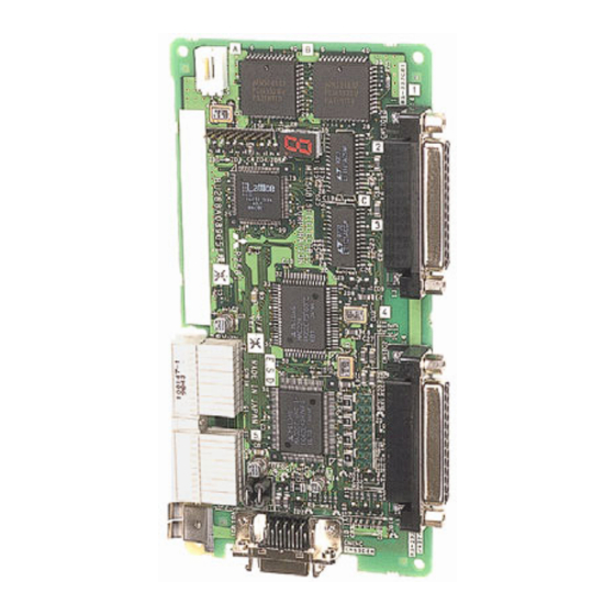
Page 93: Extended Serial Interface
3Controller (6) Extended serial interface ■ Order type: ● 2A-RZ581-E ■ Outline The extension serial interface is the option to add a serial communication function to the robot controller. One channel of RS-232C interface is provided in the front of the controller. - Page 94 3Controller ■ Functions (1) Controller communication function ・ This function allows to update and download programs as well as to monitor various statuses. ・The personal computer support software (sold separately) is available as a robot controller programming support tool. Refer to (9), Page 95, "(11) Personal computer support software/Personal computer support software mini"...
-
Page 95: Cc-Link Interface
3Controller (7) CC-Link interface ■ Order type: ● 2A-HR575-E ■ Outline The CC-Link interface is the option to not only add bit data to the robot controller. but also to add CC-Link field network function that allows cyclic transmission of word data. - Page 96 3Controller ■ Specifications Table 3-31 : Specifications Item Specifications Remarks Communication function Bit data and word data can be transmitted. Word data are used by the registers. Note1) Station type Intelligent device station Support station Local station No master station function Mountable option slot Slot 2 only Number of mountable CC-Link interface cards...
-
Page 97: Ethernet Interface
Hub (Required for use in LAN environment) (Commercially sold) Windows compatible robot controller (Separately sold) Personal computer support software programming support tool for Mitsubishi CRn- 500 series controllers Windows compatible development tool (Commercially sold) Microsoft Visual C++, Visual Basic, etc. - Page 98 3Controller ■ Functions (1) Controller communication function ・ This function allows communication with the robot controller via Ethernet. (Program upload/download, status monitoring, etc.) The personal computer support software (sold separately) is available as a robot controller programming support tool. ・ This function allows communication with a maximum of 16 clients on other end. (2) Data link function ・...
-
Page 99: Additional Axis Interface
■ Outline The additional axis interface is an interface, which uses the general-purpose servo amplifier of Mitsubishi and the corresponding servomotors in order to allow the plural above servomotors to be controlled from the robot controller. Caution) Additional axis interface can be used with a robot controller software version of G9 or later. - Page 100 3 axes Applicable amplifier MELSERVO-J2-Super series Applicable encoder ABS method only (absolute value encoder) Communication method SSCNET (differential communication) of Mitsubishi Mountable optional slots Slot 1 or 3 Number of mountable interface cards Control function Synchronous interpolation control Path control method...
-
Page 101: Extension Memory Cassette
3Controller (10) Extension memory cassette ■ Order type: ● 2A-HR432 ■ Outline Used to increase the total number of teaching points in the robot program. ■ Configuration Table 3-41 : Configuration device Part name Type Qty. Remarks 27,900 total teaching points Extension memory cassette 2A-HR432 With a battery backup feature... - Page 102 3Controller ■ Installation <When using the CR2B-574 controller> The installation method to the CR2B-574 controller is shown below. 1) Completely back up the memory information in the robot controller using the personal computer support software. (This must be performed as a preventive measure in case the contents of the internal memory are destroyed while inserting a memory cassette.) 2) Turn off the controller power.
- Page 103 3Controller <When using the CR3-535M controller> The following describes a sample installation to the R6x2CPU. 7) Completely back up the memory information in the robot controller using the personal computer support software. (This must be performed as a preventive measure in case the contents of the internal memory are destroyed while inserting a memory cassette.) 8) Turn off the control power.
-
Page 104: Personal Computer Support Software/Personal Computer Support Software Mini
3Controller (11) Personal computer support software/Personal computer support software mini (MELSOFT RT ToolBox) ■ Order type : ● Personal computer support software *For windows CD-ROM : 3A-01C-WINE ● Personal computer support software mini *For windows CD-ROM : 3A-02C-WINE ■ Outline This is handy software that fully uses the personal computer functions. - Page 105 3Controller ■ Functions Table 3-44 : Functions Note1) Function Details Functional existence Compatible model ○ ○ Personal computer running Microsoft Windows98/2000/NT 4.0/Me/XP. Program editing Editing functions ・ MELFA BASIC IV language compatible functions ・ Multiple editing screen simultaneously display ・ Command input, comment writing ・...
-
Page 106: Instruction Manual(Bound Edition)
3Controller (12) Instruction Manual(bound edition) ■ Order type : ● 4S-MAP-102 : In the case of CR2B-574controller ● 4S-MAP-105 : In the case of CR3-535M controller ■ Outline This is a printed version of the CD-ROM (instruction manual) supplied with this product. -
Page 107: Maintenance Parts
Fan (40 square) Amplifier unit Converter unit Fan (90 square) Inside of the controller Filter Rear of the controller Note1)Confirm the robot arm serial No., and contact the dealer or service branch of Mitsubishi Electric Co., for the type. Maintenance parts 3-98... -
Page 108: Software
4Software 4 Software 4.1 List of commands The available new functions in MELFA-BASIC IV are given in Table 4-1. Table 4-1 : The available new functions in MELFA-BASIC IV Class Command example Function Robot Status Variable P_TOOL keep current tool length M_SPD keep current speed (linear/circular interpolation) Built-in functions... -
Page 109: Melfa-Basic Ⅳ Commands
4Software (1) MELFA-BASIC Ⅳ commands Table 4-2 : List of MELFA-BASIC IV commands Type Class Function Input format (example) Joint interpolation Moves to the designated position with joint interpolation. MOV P1 Linear interpolation Moves to the designated position with linear interpolation. MVS P1 Circular interpolation Moves along a designated arc (start point →... - Page 110 4Software Type Class Function Input format (example) Subroutine Executes the designated subroutine. (Within program) GOSUB 200 Returns from the subroutine. RETURN Executes the designated program. CALLP "P10",M1,P1 Defines the program argument executed with the CALLP command. FPRM M10,P10 Executes the subroutine corresponding to the designated expression value. ON M1 GOSUB 100,200,300 Interrupt...
-
Page 111: List Of Parameters
4Software 4.2 List of parameters (1) List of parameters show the main parameter in the Table 4-3. Table 4-3 : List of parameters Parameter Details Standard tool coordinates. MEXTL Set the default value for the tool data. Unit: mm or deg. Standard base coordinates MEXBS Set the relation of the world coordinate system and robot coordinate system. -
Page 112: Change The Display Language / 表示言語の切 り 替え
4Software Parameter Details Hand type HANDTYPE Set the hand type of the single/double solenoid, and the signal No. (Single/double = S/D) Set the signal No. after the hand type. Example) D900 Stop input B contact desig - Change the dedicated input (stop) between the A contact and B contact. nation User-designated origin USERORG... - Page 113 4Software (2) Change the display language / 表示言語の切 り 替え The language to display on the LCD display of teaching pendant can be changed by "the display language param - eter". (Japanese or English) 4-3. Refer to the separate "Instruction Manual/Detailed Explana - Show the details of the parameter in the Table tion of Functions and Operations"...
-
Page 114: Instruction Manual
5Instruction Manual 5 Instruction Manual 5.1 The details of each instruction manuals The contents and purposes of the documents enclosed with this product are shown below. Use these documents according to the application. Instruction manuals enclosed in dashed lines in the list below are for optional products. For special specifications, a separate instruction manual describing the special section may be enclosed. - Page 115 5Instruction Manual Explains the specifications, functions and operations of the CC-Link interface optional. CC-Link inter - face Explains the specifications, functions and operations of the ETHERNET interface optional. ETHERNET interface Explains the specifications, functions and operations of the additional axis interface optional. Additional axis interface Explains the specifications, functions and operations of the Personal computer Support soft -...
-
Page 116: Safety
6Safety 6 Safety 6.1 Safety Measures to be taken regarding safety of the industrial robot are specified in the "Labor Safety and Sanitation Rules". Always follow these rules when using the robot to ensure safety. 6.1.1 Self-diagnosis stop functions This robot has the self-diagnosis stop functions shown in Table 6-1 and the stop functions shown in Table 6-2... -
Page 117: Precautions For Using Robot
6Safety 6.1.3 Precautions for using robot The safety measures for using the robot are specified in the "Labor Safety and Sanitation Rules". An outline of the rules is given below. (1) Robot installation ・ Secure sufficient work space required to safely perform work such as teaching and maintenance related to the robot. -
Page 118: Examples Of Safety Measures
6Safety 6.1.7 Examples of safety measures Two emergency stop input circuits are prepared on the user wiring terminal block of the controller. Create a cir - cuit as shown below for safety measures <Customer-prepared wiring> <Robot controller system> + To servo main circuit power External emergency External emergency RA11... - Page 119 6Safety [Reference] The specifications of the RA1 and RA2 coil shown in Fig. 6-1 are as follow. ・ Rated voltage ......DC24V ± 10% ・ Rated excitation current ..12.5mA ± 10% (at25 deg.) * Note that these specifications are subject to change without prior notice for modification purposes. The emergency stop circuit in the robot is a duplex type to ensure safety.
-
Page 120: Working Environment
6Safety 6.2 Working environment Avoid installation in the following places as the equipment's life and operation will be affected by the ambient environment conditions. When using in the following conditions, the customer must pay special attention to the preventive measures. (1) Power supply ・... -
Page 121: Precautions For Handling
For the replacement of the resin parts, please contact Mitsubishi or Mitsubishi's dealer. If the resin part is not replaced, the mechanism unit and the speed reducer may be damaged significantly when the axes collide with the mechanical stopper next or subsequent time. -
Page 122: 7Appendix
7Appendix 7 Appendix Appendix 1 : Specifications discussion material ■ Customer information Company name Name Address Telephone ■ Purchased mode Specification Type Note1) □ RV-6S □ RV-6SL □ RV-6S-SM □ RV-6SL-SM Standard specification Clean specification □ RV-6SC □ RV-6SLC Note1) Replaced with the CR3-535M controller in the case of the "-SM" specification. ■... - Page 129 HEAD OFFICE: TOKYO BUILDING, 2-7-3, MARUNOUCHI, CHIYODA-KU, TOKYO 100-8310, JAPAN NAGOYA WORKS: 5-1-14, YADA-MINAMI, HIGASHI-KU, NAGOYA 461-8670, JAPAN JUL..2007 MEE Printed in Japan on recycled paper. Specifications are subject to change without notice.
Need help?
Do you have a question about the MELFA RV-6S Series and is the answer not in the manual?
Questions and answers