Table of Contents
Advertisement
Quick Links
Advertisement
Table of Contents

Related Manuals for Keysight M8121A


Summary of Contents for Keysight M8121A
- Page 1 Keysight M8121A Arbitrary Waveform Generator User Guide...
- Page 2 HEREIN, INCLUDING BUT NOT LIMITED TO http://www.keysight.com/find/sweula. THE IMPLIED WARRANTIES OF The license set forth in the EULA represents MERCHANTABILITY AND FITNESS FOR A the exclusive authority by which the U.S. PARTICULAR PURPOSE. KEYSIGHT SHALL Keysight M8121A Arbitrary Waveform Generator User Guide...
-
Page 3: Safety Summary
Failure to comply with these precautions or with specific warnings or operating instructions in the product manuals violates safety standards of design, manufacture, and intended use of the instrument. Keysight Technologies assumes no liability for the customer's failure to comply with these requirements. Product manuals are provided with your instrument on CD-ROM and/or in printed form. - Page 4 All front-panel connectors of the M8121A are sensitive to Electrostatic discharge (ESD). There are also several exposed components on the PCAs, on both sides of M8121A, which can be touched accidentally while handling the unit and can risk damage to the instrument, due to ESD.
-
Page 5: Instrument Markings
In case the system is running for a longer time, the surface (cover and bottom) of the module can heat up to 60 degree. Therefore, the user should carefully remove the module from the AXIe chassis. Keysight M8121A Arbitrary Waveform Generator User Guide... - Page 6 This is a marking to indicate product compliance with the Canadian Interference-Causing Equipment Standard (ICES-001) The Keysight email address is required by EU directives applicable to our product. This symbol indicates separate collection for electrical and electronic equipment, mandated under EU law as of August 13, 2005. All electric and electronic equipment are required to be separated from normal waste for disposal (Reference WEEE Directive, 2002/96/EC).
-
Page 7: Table Of Contents
Installation Process Post Installation Steps How to use the M8121A Instrument M8121A Maintenance ESD Protection Power and Ventilation Requirements Thermal Protection Battery Operating Environment Fiber Optic Connector Care for Optical Data Interface (ODI) Keysight M8121A Arbitrary Waveform Generator User Guide... - Page 8 Status Bar Working with M8121A Front Panel Numeric Control Usage Tooltip Clock and Output Tab Trigger tab Marker tab Data Source Tab 4 Markers Introduction Sample Markers Pause Between Multiple Marked Samples Vector Markers Keysight M8121A Arbitrary Waveform Generator User Guide...
- Page 9 Remote Programming Overview Common Commands :ABOrt Commands :ARM Commands :TRIGger Commands :MARKer Commands :INITiate Commands :INSTrument Commands :MMEMory Commands :OUTPut Commands :SOURce Commands :STATus Commands :QUEStionable Commands :SYSTem Commands :TRACe Commands :MMEMory Commands :FORMat Subsystem Keysight M8121A Arbitrary Waveform Generator User Guide...
- Page 10 Contents :CaLibrate Commands :ODI Commands 7 Characteristics Performance Specification Operating Environment Regulatory Information Environmental Information General Index Keysight M8121A Arbitrary Waveform Generator User Guide...
-
Page 11: Introduction
Key Features / 13 Two Output Paths for Different Applications / 13 Feature Options / 14 DAC Format Modes / 17 Front Panel / 19 Related Documents / 19 Additional Documents This chapter provides an overview of M8121A Arbitrary Waveform Generator. -
Page 12: M8121A Overview
Even the most complex sequencing engine does not eliminate this basic limitation. The M8121A uses a different approach: Instead of a built-in memory, it offers a full rate Optical Data Interface (ODI) to supply the samples to the DAC at up to 12 GSa/s, which enables infinitely long scenarios to be generated with up to approx. -
Page 13: Two Output Paths For Different Applications
Functionality 1 channel 2 channel 8 GSa/s, 12 or 14 bit 12 GSa/s, 12 or 14 bit to < 8 GSa/s, 12 bit >= 8 GSa/s DC amplifier Digital Up-Conversion Low Phase Noise Keysight M8121A Arbitrary Waveform Generator User Guide... -
Page 14: Dac Format Modes
Reference Guide (Manual Part No. M8190-91050). Doublet: DAC A sends +Value, NRZ: DAC A sends value for DNRZ: DAC A and B send same value DAC-B sends –Value whole sample period Figure 1 DAC Format Modes Keysight M8121A Arbitrary Waveform Generator User Guide... - Page 15 Figure 2 DNRZ/NRZ/Doublet Frequency Response This is only comparing the idealized response of the modes, and ignores NOTE the roll off due to finite switching rise times, output RC time constant and other losses. Keysight M8121A Arbitrary Waveform Generator User Guide...
- Page 16 Best signal performance in 1st Nyquist region For time domain applications, less ripple at 2 f , more distortions than sample DNRZ Doublet More output power and flatter frequency response in 2nd Nyquist region Keysight M8121A Arbitrary Waveform Generator User Guide...
-
Page 17: Front Panel
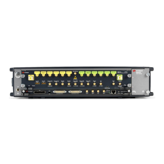
Introduction Front Panel Figure 3 on page 17 illustrates the front panel of the M8121A instrument. LPN Clk Out Flow Ctrl 1 Sample Mrk Direct Out 1 Direct Out 1 Amp Out 1 Amp Out 1 Flow Ctrl 2 Sample Mrk... - Page 18 • The green ‘Access’ LED indicates that the controlling PC exchanges data with the M8121A module. This LED blinks after power on, and remains solid after the module’s PCIe endpoint has enumerated on the bus and is ready for communication.
-
Page 19: Related Documents
Introduction Related Documents To access documentation related to the Keysight M8121A AWG, use one of the following methods: • CD - Browse the product CD for M8121A documentation. • Start > All Programs > Keysight M8121 > Keysight M8121 Documentation - Provides links to all product documentation. -
Page 21: Installation And Maintenance
User Guide Installation and Maintenance / 22 Pre-Requisites / 23 Installation Process / 31 Post Installation Steps / 32 How to use the M8121A Instrument / 33 M8121A Maintenance This chapter explains the steps required to install M8121A software package. -
Page 22: Pre-Requisites
The Keysight IO Libraries Suite can be found on the CD that is part of shipment content or at http://www.keysight.com/find/iosuite Even if a non-Keysight I/O library is already installed on your PC, it is still NOTE necessary to install the Keysight I/O library. The Keysight I/O library will install as “secondary”... -
Page 23: Installation Process
Installation and Maintenance Installation Process Follow the given steps to install Keysight M8121A software on your system: Double-click the executable (M8121A_Setup.exe). This executable file is available either on CD or Web. The installer will first check and list some pre-requisites. Click Install to NOTE install them. - Page 24 Follow the on-screen instructions to begin the installation process. Click Next. We recommend you to read the document to check if your hardware configuration is supported. Click Next to proceed to the license agreements. Keysight M8121A Arbitrary Waveform Generator User Guide...
- Page 25 Installation and Maintenance Accept the terms of Keysight software end-user license agreement and click Next. Select Yes if you want to read the post-installation instructions when finished. Click Next to select setup type. Keysight M8121A Arbitrary Waveform Generator User Guide...
- Page 26 Installation and Maintenance Select a setup type either Complete or Custom. Click Next. If you select Custom and click Next, you can specify which optional features will be installed: Keysight M8121A Arbitrary Waveform Generator User Guide...
- Page 27 Installation and Maintenance Click Next to begin installation. Keysight M8121A Arbitrary Waveform Generator User Guide...
- Page 28 Installation and Maintenance 10 The Setup Wizard will now install M8121A. Keysight M8121A Arbitrary Waveform Generator User Guide...
- Page 29 Installation and Maintenance 11 The Keysight M8121A will configure the new software installation. The following screen will appear once the Keysight M8121A software is successfully installed on your system. Click Finish to restart your system. Do not connect the AXIe chassis to your system using the PCIe cable during this reboot.
- Page 30 Installation and Maintenance 12 This completes the Keysight M8121A software installation. Keysight M8121A Arbitrary Waveform Generator User Guide...
-
Page 31: Post Installation Steps
PC with M8121A. Your PC might request a reboot. Reboot your PC, if requested. NOTE Check if the M8121A is also visible in the Keysight Connection Expert application. If something went wrong and the instrument is not showing in the Instruments tab in Keysight Connection Expert, it may be necessary to reboot the PC once more. -
Page 32: How To Use The M8121A Instrument
How to use the M8121A Instrument In order to use the instrument: When using the PCIe link to control the M8121A, the AXIe chassis must be switched on before you start the PC. The green status LED on the M8121A front panel must change from blinking to solid before switching on the external PC. -
Page 33: M8121A Maintenance
CAUTION There are also several exposed components on the PCAs, on both sides of the M8121A, which can be touched accidentally while handling the unit and can risk damage to the instrument, due to ESD. When you connect a device or cable that is not fully discharged to these connectors, you risk damage to the instrument and expensive instrument repairs. - Page 34 1 MW of isolation from ground. These techniques for a static-safe work station should not be used when WARNING working on circuitry with a voltage potential greater than 500 volts. Keysight M8121A Arbitrary Waveform Generator User Guide...
-
Page 35: Power And Ventilation Requirements
Keysight Service for repair. Battery The M8121A module does not have a battery. Operating Environment For details on the operating environment for the M8121A module, refer to the section Operating Environment on page 139. Keysight M8121A Arbitrary Waveform Generator User Guide... -
Page 36: Fiber Optic Connector Care For Optical Data Interface (Odi)
This picture shows the end of a clean, problem-free fiber-optic connector. Keysight M8121A Arbitrary Waveform Generator User Guide... - Page 37 For the 24-fiber MPO interface, purchase ® one for MPO II – MTP Brand Connectors. • Never use metal or sharp objects to clean a connector and never scrape the connector. Keysight M8121A Arbitrary Waveform Generator User Guide...
- Page 38 Always remove both ends of fiber-optic cables from any instrument, WARNING system, or device before visually inspecting the fiber ends. Disable all optical sources before disconnecting fiber-optic cables. Failure to do so may result in permanent injury to your eyes. Keysight M8121A Arbitrary Waveform Generator User Guide...
-
Page 39: Soft Front Panel
/ 43 M8121A Soft Front Panel / 51 Working with M8121A Front Panel / 53 Clock and Output Tab / 56 Trigger tab / 57 Marker tab / 58 Data Source Tab This chapter describes the M8121A Soft Front Panel. -
Page 40: Launching The M8121A Soft Front Panel
This dialog shows the addresses of the discovered M8121A modules. Select a module from the list and click “Connect”. If no M8121A module is connected to your PC, you can select “Simulation Mode” to simulate an M8121A module. Keysight M8121A Arbitrary Waveform Generator User Guide... - Page 41 Soft Front Panel New image required. Figure 6 M8121A connected in simulation mode Next, a M8121A software startup screen will be displayed as shown in Figure 7 on page 42. Keysight M8121A Arbitrary Waveform Generator User Guide...
- Page 42 Soft Front Panel Figure 7 M8121A startup screen Keysight M8121A Arbitrary Waveform Generator User Guide...
-
Page 43: M8121A Soft Front Panel
Soft Front Panel M8121A Soft Front Panel The M8121A Soft Front Panel and its GUI elements are illustrated in Figure 8 on page 43. Figure 8 M8121A user interface The M8121A Soft Front Panel includes the following GUI elements: Title Bar... -
Page 44: Title Bar
File > Load Configuration… To be implemented. Loads the previously saved configuration file. Not functional in the current software release. File > Exit Exits the M8121A application. View Menu The View menu includes the following selections: Keysight M8121A Arbitrary Waveform Generator User Guide... - Page 45 Tools Menu The Tools menu includes the following selections: Tools > SCPI Editor... Opens SCPI Editor that lists all SCPIs that can be used to program M8121A SCPI and also provides a platform to execute them. For details, see Editor on page 47.
-
Page 46: Display Settings Dialog
The Display Settings dialog allows you to set the display the GUI. Figure 9 Display Settings dialog Using this dialog, you can apply the provided setting to the interface skin, color, font, font skin, message icons, and number format. Keysight M8121A Arbitrary Waveform Generator User Guide... -
Page 47: Scpi Editor
Soft Front Panel SCPI Editor The SCPI Editor lists all SCPI that can be used to program M8121A and also provides a platform to execute them. The following figure depicts the elements of the SCPI Editor: Figure 10 SCPI Editor It has the following elements: •... -
Page 48: Status Indicator
Press the ARM button to set to an armed state. Signal generation is started after a trigger is received. This option is applicable only when Triggered option is selected under the Trigger Mode drop-down list. Keysight M8121A Arbitrary Waveform Generator User Guide... -
Page 49: Messages
Messages window It has the following controls, signs, and columns: Messages Click this button to show/hide messages. Warnings Click this button to show/hide warning messages. Errors Click this button to show/hide the error messages. Keysight M8121A Arbitrary Waveform Generator User Guide... -
Page 50: Status Bar
Instrument status - Displays the instrument status, for example “Reset complete” after issuing a reset command. • Show messages/warning/errors - Click the “Error Count” button to view the window to view messages, warnings, and errors on the Message window. Keysight M8121A Arbitrary Waveform Generator User Guide... -
Page 51: Working With M8121A Front Panel
For example, in the Frequency control you can use "H", "K", "M", or "G" to specify Hz, kHz, MHz or GHz, respectively. (The control is not case sensitive.) Keysight M8121A Arbitrary Waveform Generator User Guide... -
Page 52: Tooltip
Figure 15 Tooltip example 1 Here is another example where the tooltip provides information to the user on the minimum and maximum values the parameter can hold. Figure 16 Tooltip example 2 Keysight M8121A Arbitrary Waveform Generator User Guide... -
Page 53: Clock And Output Tab
Clock and Output Tab The Clock and Output tab is used to configure the clock and outputs of the M8121A module. It includes input fields for the clocks (Internal/External/LPN) to configure the relevant frequencies and also includes the outputs of the channel of M8121A Module. - Page 54 Normal - When the M8121A module is not configured in the M8192A module. • Master - When the M8121A module is configured as Master in the M8192A module. • Slave - When the M8121A module is configured as Slave in the M8192A module.
- Page 55 Floor” feature. When the reduced noise floor feature is enabled, there is less phase noise in the generated output signal. The M8121A has a delay adjustment in the module that allows a delay to be added to a channel’s output signal. Using the delay adjustment, a user can delay the signal on one channel compared to the signal on the other channel.
-
Page 56: Trigger Tab
Soft Front Panel Trigger tab The Trigger tab is used to configure the trigger inputs of the M8121A module. This tab has the following options: • Trigger Mode - Use this drop-down list to select the trigger mode value. The following options are available: •... -
Page 57: Marker Tab
Soft Front Panel Marker tab The Marker tab is used to configure the marker outputs of the M8121A module. This tab has the following options for Channel 1 and Channel 2. Vector Marker • Amplitude - Specifies the amplitude of the marker output signal. -
Page 58: Data Source Tab
1 and 2: • Lane Rate - Currently 14.1 Gb/s is the only supported lane rate. • Max Burst - This is the maximum burst size and is 2048 (not adjustable). Keysight M8121A Arbitrary Waveform Generator User Guide... - Page 59 • ODI Activate – This button will reactivate the ODI port. This can be used to attempt to resynchronize the M8121A ODI port with that of a ODI data producer. ODI statistics are reset whenever the ODI port is activated.
- Page 60 ODI Statistics - Display the ODI statistics in terms of Bytes Received, Bad Bursts Received, Rx Rate (Bytes/s), Bytes Sent and Tx Holdoffs. • Internal Data Source - For internal data source, the following options are available: Keysight M8121A Arbitrary Waveform Generator User Guide...
- Page 61 A 12 bit packed waveform may be loaded and used when doing a self-test of the ODI. In this case, the waveform must be a multiple of 768 samples. • The waveform memory size is 1,048,576 bytes, or 524,288 16-bit samples. Keysight M8121A Arbitrary Waveform Generator User Guide...
- Page 62 Auto scale the waveform • Load into Channel 1/2 - Click these buttons to load the waveform data to the respective channels (Channel 1and/or Channel 2). Keysight M8121A Arbitrary Waveform Generator User Guide...
- Page 63 Keysight M8121A Arbitrary Waveform Generator User Guide Markers / 64 Introduction / 64 Sample Markers / 65 Pause Between Multiple Marked Samples / 65 Vector Markers This chapter describes the markers supported by M8121A.
-
Page 64: Markers
The sample marker is always aligned to the sample data. This alignment varies depending on the mode. Delay adjustments also change the delay of the sample marker. The following drawing shows an example. The dots represent the marked samples. Keysight M8121A Arbitrary Waveform Generator User Guide... -
Page 65: Pause Between Multiple Marked Samples
This vector marker can only be set in vector clock granularity. The vector marker is an output of the pattern generation. Delay adjustments do not change the delay of the vector marker. Keysight M8121A Arbitrary Waveform Generator User Guide... - Page 66 Markers The following drawing shows an example. The dots represent the marked clock vectors. Vector Clock Marked Samples relative to Vector Clock Granularity Vector Marker Figure 20 Marked clock vectors Keysight M8121A Arbitrary Waveform Generator User Guide...
- Page 67 Direct Mode / 69 Digital Up-Conversion Modes / 69 IQ Modulation / 69 Interpolated Modes / 69 Markers in Interpolated Modes / 70 Amplitude Scaling / 71 Doublet Mode and Digital Up-Conversion This chapter describes the Digital Up-Conversion for the M8121A.
-
Page 68: Digital Up-Conversion (Requires Option Duc)
Figure 21 Hardware Structure of Features for Digital Up-Conversion The M8121A provides a direct mode, which allows sending sample data directly to the output of the instrument. Additionally, it provides mechanisms to do IQ modulation internally (highlighted in blue in Figure on page 68). -
Page 69: Digital Up-Conversion Modes
300 MSa/s 240 MHz INT_x48 150 MSa/s 120 MHz Markers in Interpolated Modes Markers can be provided for each incoming IQ sample pair. It is not possible to perform marking of interpolated sample values. Keysight M8121A Arbitrary Waveform Generator User Guide... -
Page 70: Amplitude Scaling
The marker to sample output delay is different in the digital NOTE up-conversion mode compared to the corresponding value in direct modes (For details, refer to the M8121A datasheet). Amplitude Scaling The amplitude multiplier allows to scale the amplitude of the DAC output... -
Page 71: Doublet Mode And Digital Up-Conversion
The frequency band is mirrored at the half of the sample frequency (7.2 GHz max). The content of the first Nyquist band (0 – 3.6 GHz max.) is transferred to the second Nyquist band (3.6 GHz to 7.2 GHz max.). Keysight M8121A Arbitrary Waveform Generator User Guide... -
Page 73: Remote Programming
Keysight M8121A Arbitrary Waveform Generator User Guide Remote Programming / 74 Remote Programming Overview / 78 Common Commands / 81 :ABOrt Commands / 82 :ARM Commands / 86 :TRIGger Commands / 87 :MARKer Commands / 91 :INITiate Commands / 92... -
Page 74: Remote Programming Overview
Command Line Arguments Before sending SCPI commands to the instrument, the firmware (M8121Firmware.exe) must be started. This can be done in the Windows Start menu (All Programs >Keysight M8121 > Keysight M8121). (See Communication for details about /s, /t, /i, /AutoID, /NoAutoID, /FallBack). - Page 75 • If only one AXIe module is connected to this PC and it is an M8121A module, first try to use the command line arguments /s, /t, /i or their respective default values if they are not specified. If starting the servers fails, proceed with the steps below.
- Page 76 = 60000 + 2 * <HiSLIP index> + 1 Ports may already be in use by Windows or other applications, so they NOTE are not available for M8121A. The first port not assigned by IANA is 49152 (IANA, Internet Assigned Numbers Authority, http://www.iana.org...
- Page 77 When there is more than one data parameter, they are separated by commas (,). You can add spaces around the commas to improve readability. Keysight M8121A Arbitrary Waveform Generator User Guide...
-
Page 78: Common Commands
A query of this register returns a decimal value which corresponds to the binary-weighted sum of all bits set in the register. *OPC Set the “Operation Complete” bit (bit 0) in the Standard Event register after the previous commands have been completed. Keysight M8121A Arbitrary Waveform Generator User Guide... - Page 79 Poll but the “Master Summary” bit (bit 6) is not cleared by the *STB? command. *TST? Execute Self Tests. If self-tests pass, a 0 is returned. A number lager than 0 indicates the number of failed tests. To get actual messages, use :TEST:TST? Keysight M8121A Arbitrary Waveform Generator User Guide...
- Page 80 Use :SYST:SET to send the learn string. See :SYSTem:SET[?] on page 115. *WAI? Prevents the instrument from executing any further commands until the current command has finished executing. Keysight M8121A Arbitrary Waveform Generator User Guide...
-
Page 81: Abort Commands
:ABOrt Commands :ABORt[1|2] Command :ABORt[1|2] Parameters None Parameter Suffix None Description This command stops signal generation on channel. If channels are coupled, signal generation on both channels will be stopped. Examples Command :ABOR1 Keysight M8121A Arbitrary Waveform Generator User Guide... -
Page 82: Arm Commands
0 .. 150e-12 :ARM[:SEQuence][:STARt][:LAYer]:CDELay[1|2][?] <coarse_delay>|MINimum|MAXi- Command :ARM:CDEL[?] Long :ARM[:SEQuence][:STARt][:LAYer]:CDELay[1|2][?] Parameters <coarse_delay> | MINimum | MAXimum Parameter Suffix None Description Set or query the coarse delay settings. The unit is in seconds. Examples Command :ARM:CDEL 3e-9 Keysight M8121A Arbitrary Waveform Generator User Guide... - Page 83 0/OFF – Noise reduction disabled. • 1/ON – Noise reduction enabled. Examples Command :ARM:RNO1 ON Query :ARM:RNO1? -> 1 If the noise reduction is enabled and fine delay are constant and cannot NOTE be adjusted. Keysight M8121A Arbitrary Waveform Generator User Guide...
- Page 84 Query :ARM:TRIG:IMP? :ARM[:SEQuence][:STARt][:LAYer]:TRIGger:LEVel[?] Command :ARM:TRIGger:LEVel <level>|MINimum|MAXimum Query :ARM:TRIGger:LEVel? Parameters <level>|MINimum|MAXimum Parameter Suffix None Description Set or query the trigger input threshold level. <level> – Threshold level voltage. Examples Command :ARM:TRIG:LEV 3e-9 Query :ARM:TRIG:LEV? Keysight M8121A Arbitrary Waveform Generator User Guide...
- Page 85 This query returns “1” after the trigger event is received, either from a trigger signal received at the front panel, or via the "Force Trigger" command (:TRIGger[:SEQuence][:STARt]:BEGin{1:2}[:IMMediate]/nquery/). It returns 0 after playback is stopped (:ABOR). Examples Query :ARM:TRIG:STAT1? Keysight M8121A Arbitrary Waveform Generator User Guide...
-
Page 86: Trigger Commands
Remote Programming :TRIGger Commands :TRIGger[:SEQuence][:STARt]:BEGin[1|2][:IMMediate] Command :TRIG:BEG Long :TRIGger:BEGin Parameters None Parameter Suffix None Description In triggered mode send the start/begin event to a channel. Examples Command :TRIG:BEG Keysight M8121A Arbitrary Waveform Generator User Guide... -
Page 87: Marker Commands
Command :MARK:SAMP:VOLT:AMPL 3.0e-9 Query :MARK:SAMP:VOLT:AMPL? [:SOURce]:MARKer[1|2]:SAMPle:VOLTage[:LEVel][:IMMediate]:HIGH[?] <level> Command :MARK:SAMP:VOLT:HIGH[?] Long :MARKer:SAMPle:VOLTage:HIGH[?] Parameters <level> Parameter Suffix None Description Set or query the output high level for sample marker. Examples Command :MARK:SAMP:VOLT:HIGH 1.5 Query :MARK:SAMP:VOLT:HIGH? Keysight M8121A Arbitrary Waveform Generator User Guide... - Page 88 Examples Command :MARK:SAMP:VOLT:LOW -0.5 Query :MARK:SAMP:VOLT:LOW? [:SOURce]:MARKer[1|2]:SAMPle:VOLTage[:LEVel][:IMMediate]:OFFSet[?] <level> Command :MARK:SAMP:VOLT:OFFS[?] Long :MARKer:SAMPle:VOLTage:OFFSet[?] Parameters <level> Parameter Suffix None Description Set or query the output offset for sample marker. Examples Command :MARK:SAMP:VOLT:OFFS 2.5e-9 Query :MARK:SAMP:VOLT:OFFS? Keysight M8121A Arbitrary Waveform Generator User Guide...
- Page 89 Command :MARK:VECT:VOLT:AMPL 2.5e-9 Query :MARK:VECT:VOLT:AMPL? [:SOURce]:MARKer[1:2]:VECTor:VOLTage[:LEVel][:IMMediate]:HIGH <level> Command :MARK:VECT:VOLT:HIGH[?] Long :MARKer:VECT:VOLTage:HIGH[?] Parameters <level> Parameter Suffix None Description Set or query the output high level for vector marker. Examples Command :MARK:VECT:VOLT:HIGH 1.5 Query :MARK:VECT:VOLT:HIGH? Keysight M8121A Arbitrary Waveform Generator User Guide...
- Page 90 Examples Command :MARK:VECT:VOLT:LOW -0.5 Query :MARK:VECT:VOLT:LOW? [:SOURce]:MARKer[1:2]:VECTor:VOLTage[:LEVel][:IMMediate]:OFFSet <level> Command :MARK:VECT:VOLT:OFFS[?] Long :MARKer:VECT:VOLTage:OFFSet[?] Parameters <level> Parameter Suffix None Description Set or query the output offset for vector marker. Examples Command :MARK:VECT:VOLT:OFFS 2.5e-9 Query :MARK:VECT:VOLT:OFFS? Keysight M8121A Arbitrary Waveform Generator User Guide...
-
Page 91: Initiate Commands
This command is used to set or query the continuous mode, or to set the triggered mode. 0/OFF – Continuous mode is off. 1/ON – Continuous mode is on. Trigger mode is “automatic”. Examples Command :INIT:CONT:STAT ON Query :INIT:CONT:STAT? Keysight M8121A Arbitrary Waveform Generator User Guide... -
Page 92: Instrument Commands
:TRAC[1|2]:DWID Examples Command :INST:COUP:STAT1 ON Query :INST:COUP:STAT1? :INSTrument:SLOT[:NUMBer]? Query :INSTrument:SLOT[:NUMBer]? Parameters None Parameter Suffix None Description This query returns the instrument’s slot number in its AXIe frame. Examples Query :INST:SLOT? Keysight M8121A Arbitrary Waveform Generator User Guide... -
Page 93: Mmemory Commands
This command loads the saved configuration file to the instrument. Examples Command :MMEM:LOAD:CST "C:\data.txt" :MMEMory:STORe:CSTate Command :MMEMory:STORe:CSTate <file_name> Parameters <file_name> Parameter Suffix None Description This command stores the current state of instrument to a file. Examples Command :MMEM:STOR:CST "C:\data.txt" Keysight M8121A Arbitrary Waveform Generator User Guide... -
Page 94: Output Commands
“<value>” is the offset to the calibrated optimum DAC value, so the minimum and maximum depend on the result of the calibration. Examples Command :OUTP:DIOF MAX Query :OUTP:DIOF? Keysight M8121A Arbitrary Waveform Generator User Guide... - Page 95 Command :OUTPut[1|2]:ROUTe[:SELect] DAC|DC Query :OUTPut[1|2]:ROUTe[:SELect]? Parameters DAC|DC Parameter Suffix None Description This command selects the output path: • DAC: Direct DAC output • DC: Amplified differential output Examples Command :OUTP:ROUT DAC Query :OUTP:ROUT? Keysight M8121A Arbitrary Waveform Generator User Guide...
-
Page 96: Source Commands
This command sets or queries the amplitude for the DAC or DC output path, as specified in the SCPI command. The output path can also be set using the OUTP:ROUT:SEL command (see :OUTPut[1|2]:ROUTe[:SELect][?] DAC|DC on page 95). Examples Command :DAC:VOLT:AMPL 0.685 Query :DAC:VOLT:AMPL? Keysight M8121A Arbitrary Waveform Generator User Guide... - Page 97 This command sets or queries the low level for the DAC or DC output path, as specified in the SCPI command. The output path can also be set using the OUTP:ROUT:SEL command (see :OUTPut[1|2]:ROUTe[:SELect][?] DAC|DC on page 95). Examples Command :DAC:VOLT:LOW -0.3 Query :DAC:VOLT:LOW? Keysight M8121A Arbitrary Waveform Generator User Guide...
- Page 98 This command sets or queries the termination voltage level. Examples Command :DC:VOLT:TERM 3e-1 Query :DC:VOLT:TERM? [:SOURce]:VOLTage[:LEVel][:IMMediate]:OFFSet[?] Command [:SOURce]:VOLTage[:LEVel][:IMMediate]:OFFSet <level> Query [:SOURce]:VOLTage[:LEVel][:IMMediate]:OFFSet? Parameters <level> Parameter Suffix None Description This command sets or queries the output offset. Examples Command :VOLT:OFFS 0.02 Query :VOLT:OFFS? Keysight M8121A Arbitrary Waveform Generator User Guide...
- Page 99 <frequency_fractional> | MIN | MAX | DEFault Parameter Suffix Description This command sets or queries the fractional part of the carrier frequency used for interpolated modes. <frequency_fractional> – Fractional part of the carrier frequency Keysight M8121A Arbitrary Waveform Generator User Guide...
- Page 100 [:SOURce]:CARRier[1|2]:POFFset [?] Command [:SOURce]:CARRier[1|2]:POFFset <phase- offset> |MINimum|MAXimum|DEFaultency_integral>|MIN|MAX|DEFaul Query [:SOURce]:CARRier[1|2]:POFFset? Parameters <phase-offset> | MIN | MAX | DEF Parameter Suffix None Description This command sets or queries the carrier phase offset used for interpolated modes. Keysight M8121A Arbitrary Waveform Generator User Guide...
- Page 101 This command sets or queries the amplitude scale used for interpolated modes. Examples Command :CARR1:SCAL 0.9 This command sets the carrier amplitude scale to 0.9. Query :CARR1:SCAL? -> 0.9 [:SOURce]:FREQuency:RASTer[?] Command [:SOURce]:FREQuency:RASTer <frequency>|MINimum|MAXimumency_integral>|MIN|MAX|DEF ault Query [:SOURce]:FREQuency:RASTer? Parameters <frequency>|MINimum|MAXimum Parameter Suffix None Keysight M8121A Arbitrary Waveform Generator User Guide...
- Page 102 = 250 MSa/s…500 MSa/s the sample clock input must be four Sa,i times f Sa,i For f = 125 MSa/s…250 MSa/s the sample clock input must be eight Sa,i times f Sa,i Examples Command :FREQ:RAST:EXT MIN Query :FREQ:RAST:EXT? Keysight M8121A Arbitrary Waveform Generator User Guide...
- Page 103 [:SOURce]:FREQuency:RASTer:STATus[1:2]? Query [:SOURce]:FREQuency:RASTer:STATus[1:2]? Parameters None Parameter Suffix None Description This queries the status of clock stability for each channel. It reflects the Clock LED status on the soft front panel. Examples Query FREQ:RAST:STAT1? Keysight M8121A Arbitrary Waveform Generator User Guide...
- Page 104 <frequency>|MINimum|MAXimum Query [:SOURce]:ROSCillator:FREQuency? Parameters <frequency>|MINimum|MAXimum Parameter Suffix None Description This command sets or queries the expected reference clock frequency, if the external reference clock source is selected. Examples Command :ROSC:FREQ MIN Query :ROSC:FREQ? Keysight M8121A Arbitrary Waveform Generator User Guide...
- Page 105 Description This command sets or queries the amplitude for the currently selected output path (DAC or DC, selected with the OUTP:ROUT:SEL command). :OUTPut[1|2]:ROUTe[:SELect][?] DAC|DC on page 95. Examples Command :VOLT 0.685 Query :VOLT? Keysight M8121A Arbitrary Waveform Generator User Guide...
- Page 106 This command sets or queries the low level for the currently selected output path (DAC or DC, selected with the OUTP:ROUT:SEL command). :OUTPut[1|2]:ROUTe[:SELect][?] DAC|DC on page 95. Examples Command :VOLT:LOW -0.3 Query :VOLT:LOW? Keysight M8121A Arbitrary Waveform Generator User Guide...
- Page 107 This command sets or queries the offset for the currently selected output path (DAC or DC, selected with the OUTP:ROUT:SEL command). See :OUTPut[1|2]:ROUTe[:SELect][?] DAC|DC on page 95. Examples Command :VOLT:OFFS 0.02 Query :VOLT:OFFS? Keysight M8121A Arbitrary Waveform Generator User Guide...
-
Page 108: Status Commands
Setting both positive/negative filters true allows an event to be reported anytime the condition changes. Clearing both filters disable event reporting. The contents of transition filters are unchanged by *CLS and *RST. Keysight M8121A Arbitrary Waveform Generator User Guide... - Page 109 Remote Programming :STATus:PRESet Clears all status group event registers. Presets the status group enables PTR and NTR registers as follows: ENABle = 0x0000, PTR = 0xffff, NTR = 0x0000 Keysight M8121A Arbitrary Waveform Generator User Guide...
-
Page 110: Questionable Commands
Set or queries the positive-transition register in the questionable status group. A positive transition filter allows an event to be reported when a condition changes from false to true. Setting both positive/negative filters Keysight M8121A Arbitrary Waveform Generator User Guide... - Page 111 Remote Programming true allows an event to be reported anytime the condition changes. Clearing both filters disable event reporting. The contents of transition filters are unchanged by *CLS and *RST. Keysight M8121A Arbitrary Waveform Generator User Guide...
-
Page 112: System Commands
This query returns the HiSLIP number used by the firmware. Examples Query :SYST:COMM:HISL? :SYSTem:COMMunicate:SOCKet[:PORT]? Query :SYSTem:COMMunicate:SOCKet[:PORT]? Parameters None Parameter Suffix None Description This query returns the socket port used by the firmware. Examples Query :SYST:COMM:SOCK? Keysight M8121A Arbitrary Waveform Generator User Guide... - Page 113 None Description This query returns the telnet port used by the firmware. Examples Query :SYST:COMM:TELN? :SYSTem:ERRor:COUNT? Query :SYSTem:ERRor:COUNT? Parameters None Parameter Suffix None Description This query returns the error count. Examples Query :SYST:ERR:COUNT? Keysight M8121A Arbitrary Waveform Generator User Guide...
- Page 114 The response is a <DEFINITE LENGTH ARBITRARY BLOCK RESPONSE DATA> element. The full path for every command and query is returned separated by line feeds. The syntax of the response is defined as: Keysight M8121A Arbitrary Waveform Generator User Guide...
- Page 115 In set form, the block data must be a complete instrument set-up read using the query form of the command. This command has the same functionality as the *LRN command. Examples Command :SYST:SET <binary block data> Keysight M8121A Arbitrary Waveform Generator User Guide...
- Page 116 Remote Programming Query :SYST:SET? :SYSTem:VERSion? Query :SYSTem:VERSion? Parameters None Parameter Suffix None Description This query returns a formatted numeric value corresponding to the SCPI version number for which the instrument complies. Examples Query :SYST:VERS? Keysight M8121A Arbitrary Waveform Generator User Guide...
-
Page 117: Trace Commands
Remote Programming :TRACe Commands :TRACe commands should be used when working with the M8121A internal memory. With the exception of the :TRACe[1|2]:DWIDth[?] command, they do not apply when streaming data over the ODI port. :TRACe commands must follow the waveform length rules as outlined in NOTE the Data Source Tab section. - Page 118 In 12-bit mode bits 2 and 3 are don’t-care. The same data format can be used for both modes. In speed mode the two least significant bits are simply ignored. Keysight M8121A Arbitrary Waveform Generator User Guide...
- Page 119 The 12-bit packed format is useful to mimic the data format needed when sending data over the ODI to the M8121A in 12-bit mode. The packing is required in order to fit within the data bandwidth of the ODI. When using the 12-bit packed format, there are no marker bits.
- Page 120 This command associates a comment to a segment. The query gets the comment for a segment. <segment_id> – id of the segment, must be 1. <comment> – string of at most 256 characters Examples Command :TRAC:COMM 1, “Comment” Query :TRAC:COMM? 1 Keysight M8121A Arbitrary Waveform Generator User Guide...
- Page 121 If length is exceeded error -223 (too much data) is reported. Examples Command Load data consisting of 320 samples as comma-separated list into previously defined segment 1 starting at sample offset 0. :TRAC1:DATA 1,0,0,1,2,…,319 Query :TRAC:DATA? 1,0,48 Keysight M8121A Arbitrary Waveform Generator User Guide...
- Page 122 To define a segment with id 1 and length 320 samples. Initialize to sample value 0. :TRAC1:DEF 1,320,0 To set interpolated mode, interpolation factor 3. :TRAC1:DWID INTX3 To define a segment with id 1 and length 64 samples. Initialize with I/Q value pair (0,1). :TRAC:DEF 1,64,0,1 Keysight M8121A Arbitrary Waveform Generator User Guide...
- Page 123 :TRACe[1|2]:DWIDth? Parameters WSPeed|WPRecision|INTX3|INTX12|INTX24|INTX48 • WSPeed – speed mode, 12 bit DAC resolution • WPRecision – precision mode, 14 bit DAC resolution • INTX3 – interpolation x3 mode • INTX12 – interpolation x12 mode Keysight M8121A Arbitrary Waveform Generator User Guide...
- Page 124 None Description <segment_id> – id of the segment, must be 1. Delete a segment. The command can only be used in program mode. Examples Command :TRAC:DEL 5 :TRACe[1|2]:DELete:ALL Command :TRACe[1|2]:DELete:ALL Query Parameters None Keysight M8121A Arbitrary Waveform Generator User Guide...
- Page 125 <segment_id> - Id of the segment must be 1 • <file_name> file name. • <type> BIN. File format. • <padding> ALENgth|FILL. • <dac_value> a DAC value in binary format Examples :TRAC1:IMP 1, "C:\Program Files (x86)\Keysight\M8121\ Examples\WaveformDataFiles\Sin1MHzAt7p68GHz.bin", BIN Keysight M8121A Arbitrary Waveform Generator User Guide...
- Page 126 This command associates a name to a segment. The query gets the name for a segment. <segment_id> – Id of the segment must be 1 <name> – string of at most 32 characters Examples Command :TRAC:NAME 1,”ADY” Query :TRAC:NAME? 1 Keysight M8121A Arbitrary Waveform Generator User Guide...
-
Page 127: Mmemory Commands
<file_type> is always empty. <file_size> provides the size of the file in bytes. In case of directories, <file_entry> is surrounded by square brackets and both <file_type> and <file_size> are empty. Examples Query :MMEM:CAT? Keysight M8121A Arbitrary Waveform Generator User Guide... - Page 128 The second and fourth parameters specify the directories. The first pair of parameters specifies the source. The second pair specifies the destination. An error is generated if the source doesn't exist or the destination file already exists. Keysight M8121A Arbitrary Waveform Generator User Guide...
- Page 129 :MMEM:DATA “C:\data.txt”, #14test :MMEMory:DELete Command :MMEMory:DELete <file_name>[,<directory_name>] Parameters <file_name> Parameter Suffix None Description This command removes a file from the specified directory. The <file_name> parameter specifies the file to be removed. Examples Command :MMEM:DEL "C:\data.txt" Keysight M8121A Arbitrary Waveform Generator User Guide...
- Page 130 The first pair of parameters specifies the source. The second pair specifies the destination. An error is generated if the source doesn't exist or the destination file already exists. Examples Command :MMEM:MOVE "C:\data_dir","C:\newdata_dir" Keysight M8121A Arbitrary Waveform Generator User Guide...
-
Page 131: Format Subsystem
Parameter Suffix None Description Byte ORDer. Controls whether binary data is transferred in normal (“big endian”) or swapped (“little endian”) byte order. Affects [:SOURce]:SEQuence:DATA, [:SOURce]:STABle:DATA and TRACe:DATA. Examples Command :FORM:BORD NORM Query :FORM:BORD? Keysight M8121A Arbitrary Waveform Generator User Guide... -
Page 132: Calibrate Commands
:CaLibrate Commands The :CALibrate commands are used to control the latency from the M8131A digitizer to the M8121A AWG. This set of commands should be used only when controlling both instruments. The end effect is that the delay from the analog input of the digitizer to the analog output of the AWG is a fixed latency for a given setup. - Page 133 Description This command executes a step in the latency calibration of the data path between M8131A digitizer (master) and M8121A AWG (slave). In a 2 channel AWG, affects both channels if enabled. If both channels can be successfully calibrated, then they will be adjusted to ensure that they use the same latency i.e.
- Page 134 M8131A) when using a reduced noise floor or LPN clock. Otherwise, the resolution is the same as the fine delay setting. After setting this value, the user may read the value as used by the M8121A using :CALibrate:LATency:VALue?. Note that there could be a difference in ~40 ns in reported minimum latency after calibration.
- Page 135 Returns 1 if deterministic latency adjustment is currently valid, and 0 if deterministic latency adjustment has either not yet been performed, has failed to complete, or has become invalid. Examples CALibrate:LATency:STATus? Keysight M8121A Arbitrary Waveform Generator User Guide...
-
Page 136: Odi Commands
:ODI Commands The :ODI commands are documented in the AXIe standard document (http://www.axiestandard.org/odispecifications.html). Please refer to the AXIe standard documentation for details on these commands. The following is a listing of the :ODI commands supported by the M8121A: :ODI:PORT[N]:ACTivate :ODI:PORT[N]:CAPability:DIRection? :ODI:PORT[N]:CAPability:FCONtrols? - Page 137 Parameters OFF|ON Parameter Suffix None Description This command turns on/off the ODI test source (from waveform memory). This is useful for debugging the ODI interface such as during interoperability testing. Examples :TEST:ODI:PORT:TRAN ON Keysight M8121A Arbitrary Waveform Generator User Guide...
-
Page 139: Performance Specification
Keysight M8121A Arbitrary Waveform Generator User Guide Characteristics / 139 Performance Specification / 139 Operating Environment / 140 Regulatory Information / 141 Environmental Information / 141 General Performance Specification The performance specification can be found in the Data Sheet of the M8121A at: http://www.keysight.com/find/M8121A. -
Page 140: Regulatory Information
Acoustic statement: (European Machinery Directive) Acoustic noise emission LpA <70 dB Operator position Normal operation mode per ISO 7779 To find a current Declaration of Conformity for a specific Keysight product, go to: http://www.keysight.com/go/conformity Keysight M8121A Arbitrary Waveform Generator User Guide... -
Page 141: Environmental Information
Environmental Information Samples of this product have been type tested in accordance with the Keysight Environmental Test Manual and verified to be robust against the environmental stresses of Storage, Transportation and End-use; those stresses include but are not limited to temperature, humidity, shock, vibration, altitude and power line conditions. -
Page 143: Index
Numeric Control Usage, ESD Protection, Examples, Using M8121A Instrument, Utilities menu, Operating Environment, Operating environment, Fan failure, Optical Data Interface, Feature Options, Optional DC coupled amplifier, Ventilation requirements, File menu, Overheating detection, View menu, Keysight M8121A Arbitrary Waveform Generator User Guide... - Page 144 This information is subject to change without notice. © Keysight Technologies 2019 Edition 3.0, November 2019 www.keysight.com...
Need help?
Do you have a question about the M8121A and is the answer not in the manual?
Questions and answers