Keysight M9383A Startup Manual
Pxie vector signal generator
Hide thumbs
Also See for M9383A:
- Startup manual (82 pages) ,
- Security manual (28 pages) ,
- Programming manual (54 pages)
Table of Contents
Advertisement
Quick Links
Advertisement
Table of Contents

Related Manuals for Keysight M9383A


Summary of Contents for Keysight M9383A
- Page 1 Keysight M9383A PXIe Vector Signal Generator Startup Guide...
- Page 2 WARNING notice until the DOCUMENT OR ANY INFORMATION reproduce, release, perform, indicated conditions are fully CONTAINED HEREIN. SHOULD display, or disclose commercial understood and met. KEYSIGHT AND THE USER HAVE A computer software or SEPARATE WRITTEN AGREEMENT commercial computer software WITH WARRANTY TERMS...
- Page 3 Information on preventing instrument damage can be found at: http://keysight.com/find/PreventingInstrumentRepair Is your product software up-to-date? Periodically, Keysight releases software updates to fix known defects and incorporate product enhancements. To search for software updates for your product, go to the Keysight Technical Support website at: http://www.keysight.com/find/techsupport...
-
Page 5: Table Of Contents
Inspect for Damage ............13 Verify M9383A Shipment Contents and Model Options ......13 M9383A Shipment Contents . - Page 6 Locations for Keysight Technologies........
- Page 7 “Protecting against electrostatic discharge” on page 10 “Unpack and Inspect the Modules” on page 11 “Assemble the M9383A” on page 24 “Verify Operation of the Keysight M9383A PXIe Vector Signal Generator” on page 53 “Return an Instrument for Service” on page 60...
-
Page 8: Introduction
Introduction The scope of this Startup Guide is to detail the processes of installing the modules and cables that compose the M9383A PXIe Vector Signal Generator. This document also details how to install the required software. If you have any questions after reviewing this information, contact your local Keysight Technologies Inc. -
Page 9: Items You Will Need
Alternatively, you can find most of these documents under: Start > All Programs > Keysight M9383. The Data Sheet and Configuration Guide can be found on Keysight.com — To find the very latest versions of the user documentation, go to the product website www.keysight.com/find/M9383A... -
Page 10: Protecting Against Electrostatic Discharge
Additional Information About ESD For more information about ESD and how to prevent ESD damage, contact the Electrostatic Discharge Association (http://www.esda.org). The ESD standards developed by this agency are sanctioned by the American National Standards Institute (ANSI). M9383A Startup Guide... -
Page 11: Unpack And Inspect The Modules
— Contact the nearest Keysight Technologies office. — Keep the shipping materials for the carrier's inspection. — If you must return the M9383A VSG to Keysight Technologies, use the “Return an Instrument original (or comparable) shipping materials. Refer to for Service”... -
Page 12: M9383A Shipment Contents
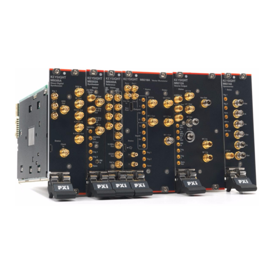
When the M9305A Direct Digital Synthesizer is paired with the M9303A Synthesizer, it can be used to improve phase noise performance (up to 20 dB) of the M9383A VSG. The M9318A Vector Modulator is another PXIe module designed to work with M9383A VSG. - Page 13 Cable, coaxial, SMB (female) - SMP (female) 150 mm Configuration 2 (Analog 31.8/44 GHz) Shipment Contents Keysight Part Number Description M9300A Keysight M9300A PXIe Frequency Reference Option M9383A-300 M9303A Keysight M9303A PXIe Synthesizer M9312A Keysight M9312A PXIe Source Output M9314A...
- Page 14 Cable, coaxial, SMB (female) - SMP (female) 150 mm Configuration 4 (Analog 31.8/44 GHz with Enhanced Phase Noise) Shipment Contents Keysight Part Number Description M9300A Keysight M9300A PXIe Frequency Reference Option M9383A-300 M9303A Keysight M9303A PXIe Synthesizer M9312A Keysight M9312A PXIe Source Output M9314A...
- Page 15 Cable, coaxial, SMP (female) - SMP (female) 200 mm Configuration 5A (Vector 14/20 GHz, with 160 MHz Bandwidth) Shipment Contents Keysight Part Number Description M9300A Keysight M9300A PXIe Frequency Reference Option M9383A-300 M9303A Keysight M9303A PXIe Synthesizer M9316A Keysight M9316A PXIe Digital Vector Modulator M9312A...
- Page 16 Cable, coaxial, SMB (female) - SMP (female) 210 mm Configuration 6 (Vector 31.8/44 GHz, with 160 MHz bandwidth) Shipment Contents Keysight Part Number Description M9300A Keysight M9300A PXIe Frequency Reference Option M9383A-300 M9303A Keysight M9303A PXIe Synthesizer M9316A Keysight M9316A PXIe Digital Vector Modulator M9312A...
- Page 17 Cable, coaxial, SMP (female) - SMP (female) 200 mm Configuration 7A (Vector 14/20 GHz, with 1 GHz Bandwidth) Shipment Contents Keysight Part Number Description M9300A Keysight M9300A PXIe Frequency Reference Option M9383A-300 M9303A Keysight M9303A PXIe Synthesizer M9312A Keysight M9312A PXIe Source Output M9318A...
- Page 18 Cable, coaxial, SMB (female) - SMP (female) 210 mm Configuration 8 (Vector 31.8/44 GHz, with 1 GHz Bandwidth) Shipment Contents Keysight Part Number Description M9300A Keysight M9300A PXIe Frequency Reference Option M9383A-300 M9303A Keysight M9303A PXIe Synthesizer M9312A Keysight M9312A PXIe Source Output M9314A...
- Page 19 Configuration 9 (Vector 14/20 GHz, with 160 MHz Bandwidth and Enhanced Phase Noise) Shipment Contents Keysight Part Number Description M9300A Keysight M9300A PXIe Frequency Reference Option M9383A-300 M9303A Keysight M9303A PXIe Synthesizer M9316A Keysight M9316A PXIe Digital Vector Modulator M9312A...
- Page 20 Cable, coaxial, SMP (female) - SMP (female) 200 mm Configuration 11 (Vector 14/20 GHz, with 1 GHz Bandwidth and Enhanced Phase Noise) Shipment Contents Keysight Part Number Description M9300A Keysight M9300A PXIe Frequency Reference Option M9383A-300 M9303A Keysight M9303A PXIe Synthesizer M9312A Keysight M9312A PXIe Source Output M9314A...
- Page 21 Cable, coaxial, SMP (female) - SMP (female) 200 mm Configuration 12 (Vector 31.8/44 GHz, with 1 GHz Bandwidth and Enhanced Phase Noise) Shipment Contents Keysight Part Number Description M9300A Keysight M9300A PXIe Frequency Reference Option M9383A-300 M9303A Keysight M9303A PXIe Synthesizer M9312A Keysight M9312A PXIe Source Output M9314A...
- Page 22 Configuration 12A (Vector 31.8/44 GHz, with 1 GHz Bandwidth, Enhanced Phase Noise, and Increased Output Power) Shipment Contents Keysight Part Number Description M9300A Keysight M9300A PXIe Frequency Reference Option M9383A-300 M9303A Keysight M9303A PXIe Synthesizer M9312A Keysight M9312A PXIe Source Output M9314A...
- Page 23 Cable, coaxial, SMP (female) - SMP (female) 150 mm 8121-2723 Cable, coaxial, SMB (female) - SMP (female) 150 mm 8121-2859 Cable, coaxial, SMP (female) - SMP (female) 200 mm For information about the available list of M9383A options, refer to the M9383A Configuration Guide M9383A Startup Guide...
-
Page 24: Assemble The M9383A
— To maintain proper airflow within the chassis, all empty chassis slots must be fitted with slot blockers (Keysight model Y1212A, 5 per kit) and EMC filler panels (Keysight model Y1213A, 5 per kit). This includes any empty slots to the left of slot 1. -
Page 25: Chassis Air Flow
HIGH ensures maximum cooling with all chassis. Chassis Air Flow The Keysight M9018B/M9019B has multiple air intakes. They are located at the lower sides, lower front, and bottom of the chassis. Cable and Connector Care... -
Page 26: Prepare The Pxie Chassis
Install the Controller Use the instructions below for installing the embedded controller (Keysight model M9037A) or the remote controller (Keysight M9021A Cable Interface with the M9048A adapter for desktop PC). -
Page 27: Embedded Controller
Startup Guide Assemble the M9383A Embedded Controller M9037A Startup Guide) (For additional details, refer to instructions in the “Protecting against electrostatic discharge” on Observe ESD Precautions: page 10 M9383A Startup Guide... - Page 28 Startup Guide Assemble the M9383A 1. Install the embedded controller in Slot 1 in the chassis. Generic module installation shown. It may not reflect your module's actual size and chassis placement. a. While holding the module by the injector/ejector handle and...
- Page 29 Startup Guide Assemble the M9383A Remote Controller If your configuration contains a M9021A Cable Interface Module, follow the procedure below. For additional information about installing the M9021A, refer to the M9021A Installation Guide. 1. Locate slot 1 in the chassis. It has this icon above it 2.
- Page 30 Startup Guide Assemble the M9383A 3. On the M9021A module, set both S301 switches to the “Host” (right-hand) position and set the S201 rocker switch to the left-hand position. Refer to the following figure for M9021A switch locations and positions.
-
Page 31: Install The Pxie Modules
Startup Guide Assemble the M9383A 1. Install the M9021A in an x8 hybrid slot in the PXIe chassis (M9018B/M9019A chassis slots 2, 6, 11, or 15). 2. Reverse the switch settings from those noted in the above procedure: — On the M9021A module, set both S301 switches to “Host” and set the S201 rocker switch to the left-hand position. -
Page 32: Cable The Modules
3. Tighten the module retaining screws (top and bottom) and torque them to 5 in-lb (0.57 N-m). Keysight recommends you install all the modules in the exact order. Generic module installation shown. It may not reflect your module's actual size and chassis placement. -
Page 33: Recommended Analog Configurations
Recommended Analog Configurations It is necessary to perform amplitude accuracy adjustment for the cables/ports before use in any 44 GHz M9383A configurations. For information on how to perform amplitude accuracy adjustment, refer to the Set Amplitude Accuracy Adjustment topic in the M9383A SFP Help. -
Page 34: Configuration 2 (Analog 31.8/44 Ghz)
Startup Guide Assemble the M9383A Configuration 2 (Analog 31.8/44 GHz) Order Cable Part Number Module Connector Module Connector 8121-2554 M9303A 100 MHz Out M9312A 100 MHz In 8121-2723 M9303A 100 MHz In M9300A 100 MHz Out 1 M9383-20024 M9303A 4.8 GHz Clock 2 Out M9312A 4.8 GHz In... -
Page 35: Configuration 3 (Analog 14/20 Ghz With Enhanced Phase Noise)
Startup Guide Assemble the M9383A Configuration 3 (Analog 14/20 GHz with Enhanced Phase Noise) Order Cable Part Number Module Connector Module Connector M9383-20021 M9305A RF Out M9303A RF In M9383-20022 M9305A 4.8 GHz In M9303A 4.8 GHz Clock 1 Out... -
Page 36: Configuration 4 (Analog 31.8/44 Ghz With Enhanced Phase Noise)
Startup Guide Assemble the M9383A Configuration 4 (Analog 31.8/44 GHz with Enhanced Phase Noise) Order Cable Part Number Module Connector Module Connector M9383-20021 M9305A RF Out M9303A RF In M9383-20022 M9305A 4.8 GHz In M9303A 4.8 GHz Clock 1 Out... -
Page 37: Configuration 5A (Vector 14/20 Ghz, With 160 Mhz Bandwidth)
Startup Guide Assemble the M9383A Configuration 5A (Vector 14/20 GHz, with 160 MHz Bandwidth) Order Cable Part Number Module Connector Module Connector M9383-20002 M9303A RF Out M9312A LO 1 In M9383-20013 M9303A 4.8 GHz Clock 2 Out M9312A 4.8 GHz In... -
Page 38: Configuration 5B (Vector 14/20 Ghz, With 160 Mhz Bandwidth)
Startup Guide Assemble the M9383A Configuration 5B (Vector 14/20 GHz, with 160 MHz Bandwidth) Order Cable Part Number Module Connector Module Connector M9383-20015 M9303A RF Out M9312A LO 1 In M9383-20016 M9303A 4.8 GHz Clock 2 Out M9312A 4.8 GHz In... -
Page 39: Configuration 6 (Vector 31.8/44 Ghz, With 160 Mhz Bandwidth)
Startup Guide Assemble the M9383A Configuration 6 (Vector 31.8/44 GHz, with 160 MHz bandwidth) Order Cable Part Number Module Connector Module Connector 8121-2723 M9303A 100 MHz In M9300A 100 MHz Out 1 8121-2859 M9303A 100 MHz Out M9312A 100 MHz In... -
Page 40: Configuration 7A (Vector 14/20 Ghz, With 1 Ghz Bandwidth)
Startup Guide Assemble the M9383A Configuration 7A (Vector 14/20 GHz, with 1 GHz Bandwidth) Order Cable Part Number Module Connector Module Connector M9383-20002 M9303A RF Out M9312A LO 1 In M9383-20013 M9303A 4.8 GHz Clock 2 Out M9312A 4.8 GHz In... -
Page 41: Configuration 7B (Vector 14/20 Ghz, With 1 Ghz Bandwidth)
Startup Guide Assemble the M9383A Configuration 7B (Vector 14/20 GHz, with 1 GHz Bandwidth) Order Cable Part Number Module Connector Module Connector M9383-20015 M9303A RF Out M9312A LO 1 In M9383-20016 M9303A 4.8 GHz Clock 2 Out M9312A 4.8 GHz In... -
Page 42: Configuration 8 (Vector 31.8/44 Ghz, With 1 Ghz Bandwidth)
Startup Guide Assemble the M9383A Configuration 8 (Vector 31.8/44 GHz, with 1 GHz Bandwidth) Order Cable Part Number Module Connector Module Connector 8121-2723 M9303A 100 MHz In M9300A 100 MHz Out 1 8121-2859 M9303A 100 MHz Out M9312A 100 MHz In... -
Page 43: Configuration
Startup Guide Assemble the M9383A Configuration 9 (Vector 14/20 GHz, with 160 MHz Bandwidth and Enhanced Phase Noise) Order Cable Part Number Module Connector Module Connector M9383-20021 M9305A RF Out M9303A RF In M9383-20022 M9305A 4.8 GHz In M9303A 4.8 GHz Clock 1 Out... -
Page 44: Configuration
Startup Guide Assemble the M9383A Configuration 10 (Vector 31.8/44 GHz, with 160 MHz Bandwidth and Enhanced Phase Noise) Order Cable Part Number Module Connector Module Connector M9383-20021 M9305A RF Out M9303A RF In M9383-20022 M9305A 4.8 GHz In M9303A 4.8 GHz Clock 1 Out... - Page 45 Startup Guide Assemble the M9383A Order Cable Part Number Module Connector Module Connector M9305-20042 M9305A Clock Out M9305A Clock In M9316-20016 M9316A LO 2 In M9316A LO 2 Out M9314-20008 M9314A LO 1 In M9314A LO 1 Out M9383A Startup Guide...
- Page 46 Startup Guide Assemble the M9383A Configuration 11 (Vector 14/20 GHz, with 1 GHz Bandwidth and Enhanced Phase Noise) Order Cable Part Number Module Connector Module Connector M9383-20021 M9305A RF Out M9303A RF In M9383-20022 M9305A 4.8 GHz In M9303A 4.8 GHz Clock 1 Out...
- Page 47 Startup Guide Assemble the M9383A Configuration 12 (Vector 31.8/44 GHz, with 1 GHz Bandwidth and Enhanced Phase Noise) Order Cable Part Number Module Connector Module Connector M9383-20021 M9305A RF Out M9303A RF In M9383-20022 M9305A 4.8 GHz In M9303A 4.8 GHz Clock 1 Out...
- Page 48 Startup Guide Assemble the M9383A Order Cable Part Number Module Connector Module Connector M9314-20008 M9314A LO 1 In M9314A LO 1 Out M9383A Startup Guide...
-
Page 49: Configuration 12A (Vector 31.8/44 Ghz, With 1 Ghz Bandwidth, Enhanced Phase Noise, And Increased Output Power)
Startup Guide Assemble the M9383A Configuration 12A (Vector 31.8/44 GHz, with 1 GHz Bandwidth, Enhanced Phase Noise, and Increased Output Power) Order Cable Part Number Module Connector Module Connector M9383-20021 M9305A RF Out M9303A RF In M9383-20022 M9305A 4.8 GHz In M9303A 4.8 GHz Clock 1 Out... -
Page 50: Install Slot Blockers And Filler Panels
LO 1 Out Install Slot Blockers and Filler Panels To assure proper operating temperatures, install slot blockers (Keysight model Y1212A, 5 per kit) and EMC filler panels (Keysight model Y1213A, 5 per kit) in empty module slots. M9383A Startup Guide... -
Page 51: Power Up The Chassis
- Run one of the operating systems listed in System Requirements (above) Remote controller (Keysight M9018A chassis only) A PC running one of the operating systems listed in System Requirements above and a Keysight M9021A Cable Interface x8 with the following PC interface option:... - Page 52 * The software is already installed on instrument configurations that include the M9037A embedded controller. The Keysight Instrument Control DVD, which includes the IO Libraries Suite software, is no longer shipped with Keysight instruments. If you require a Keysight Instrument Control DVD, it can be ordered by contacting your local Keysight Customer Contact Center.
-
Page 53: Verify Operation Of The Keysight M9383A Pxie Vector Signal Generator
“Cable The Modules” on page 32 for proper cabling. Allow the M9383A VSG to warm up for at least 30 minutes before using. 1. Select Start > All Programs > Keysight M9383 > M9383 SFP to open the M9383A SFP. -
Page 54: Run Internal Alignments
If the Self Test passes (see results below), proceed with Run Internal Alignments. If the M9383A Self Test fails, it indicates which module is likely to need service. However, you must return all modules (except the M9300A) and all cables. See “Return... - Page 55 If not all modules and their slot locations are visible in the SFP “Connect to Instrument” dialog: 1. Close the SFP. 2. Start Keysight Connection Expert, by selecting Start > All Programs > Keysight Connection Expert. If any or all modules and their slot locations are still not visible, select Refresh All.
- Page 56 Startup Guide Verify Operation of the Keysight M9383A PXIe Vector Signal Generator M9383A Startup Guide...
-
Page 57: Status Led States
Generate and View an Output Signal The following measurement uses a Keysight M9383A PXIe Vector Signal Generator to generate the 2 GHz signal and Keysight M9393A PXIe Vector Signal Analyzer to analyze it. You may use any frequency depending upon the signal analyzer used. - Page 58 Verify Operation of the Keysight M9383A PXIe Vector Signal Generator 1. Open the SFP of the M9383A VSG and the M9393A VSA. a. Select Start > All Programs > Keysight M9383 > M9383 SFP to open the M9383A SFP. b. Select Start > All Programs > Keysight > M9393 > M9393 SFP to open the M9393A SFP.
- Page 59 Startup Guide Verify Operation of the Keysight M9383A PXIe Vector Signal Generator c. Acquisition: Spectrum 6. Below the display, select Continuous for a sustained sweep of the analyzer. You should see the following display on your M9393A SFP. The frequency of the signal is 2 GHz and the amplitude is -10 dBm.
-
Page 60: Return An Instrument For Service
— “Service Options” on page 62 Calling Keysight Technologies Keysight Technologies has offices around the world to provide you with complete support for your instrument. To obtain servicing information or to order replacement parts, contact the nearest Keysight Technologies office listed below. -
Page 61: Packaging The Instrument
4. Seal the shipping container securely with strong nylon adhesive tape. 5. Mark the shipping container “FRAGILE, HANDLE WITH CARE” to assure careful handling. M9383A Startup Guide... -
Page 62: Service Options
6. Retain copies of all shipping papers. Service Options Keysight Technologies offers several optional maintenance plans to service your instrument after the warranty has expired. Call your Keysight Technologies office for full details. If you want to service the instrument yourself after the warranty expires, you can download the service documentation that provides all necessary troubleshooting and maintenance information from the Keysight web page. -
Page 63: Appendix
Reference module internal/external setting, but the changes made by other applications will not be reflected in the Keysight 89600. FPGA updates are not allowed on a Keysight M9300A PXIe Frequency Reference while it is being shared. To perform M9300A FPGA updates, reserve the Reference. -
Page 64: Api Overview
ShareReferenceVisaSession=0 Advanced Option, you will get the resource locked error shown above. API Overview Keysight's IVI drivers simplify the creation and maintenance of instrument control applications in a variety of development environments; they allow programmatic control of instrumentation while providing a greater degree of instrument interchangeability and code reuse. -
Page 65: Chassis Triggers
Triggering panel or PXI backplane triggers. You must set up the PXI chassis trigger lines to enable the M9383A trigger routing feature for backplane triggers crossing chassis segments. For more information about backplane triggers, refer to Managing Triggers chapter in the M9383A PXIe Vector Signal Generator Soft Front Panel Help. - Page 66 Startup Guide Appendix M9383A Startup Guide...
- Page 67 Keysight M9383A PXIe Vector Signal Generator Startup Guide Safety and Maintenance Information The following topics can be found in this section: “Safety Information” on page 68 “Warnings, Cautions, and Notes” on page 69 “Instrument Markings” on page 72 “Instrument Maintenance” on page 75...
-
Page 68: Safety And Maintenance Information
10°C from the lowest, of the maximum operating temperature of a single instrument. If there are any concerns or special requirements a Keysight Field Engineer should be consulted to assure instrument(s) temperature compliance and performance. -
Page 69: Warnings, Cautions, And Notes
Do not proceed beyond a caution until you fully understand the indicated conditions. Note calls the user’s attention to an important point or special information in the text. M9383A Startup Guide... -
Page 70: General Safety Considerations
Before Applying Power Use a Keysight supplied power cord that has the same or better electrical rating. Capable of rendering an electrical shock or burn. -
Page 71: Servicing
No operator serviceable parts inside. Refer servicing to qualified personnel. To prevent electrical shock do not remove covers. Operating Conditions This product is designed for use in Installation Category II and Pollution Degree 2. M9383A Startup Guide... -
Page 72: Instrument Markings
This symbol indicates the surface can be hot. This symbol indicated the product is sensitive to electrostatic discharge. This symbol identifies the Protective Conductor terminal. This symbol indicates the equipment is protected throughout by double or reinforced insulation. M9383A Startup Guide... - Page 73 The UK conformity mark is a UK government owned mark. Products showing this mark comply with all applicable UK regulations. The Keysight email address is required by EU directives applicable to our product. The CSA mark is a registered trademark of the CSA International.
- Page 74 GB 18455-2001 as required by the China RoHS regulations for paper/fiberboard packaging. This mark indicates product has been designed to meet the requirements of "IP x y", where "x" is the solid particle protection and "y" is the liquid ingress protection. M9383A Startup Guide...
-
Page 75: Instrument Maintenance
To prevent electrical shock, disconnect the instrument from mains before cleaning. Use a dry cloth or one slightly dampened with water to clean the external case parts. Do not attempt to clean internally. M9383A Startup Guide... -
Page 76: Returning An Instrument For Service
Returning an Instrument for Service Returning an Instrument for Service Calling Keysight Technologies Keysight Technologies has offices around the world to provide you with complete support for your instrument. To obtain servicing information or to order replacement parts, contact the nearest Keysight Technologies office listed below. -
Page 77: Service Options
Returning an Instrument for Service Service Options Keysight Technologies offers several optional maintenance plans to service your instrument after the warranty has expired. Call your Keysight Technologies office for full details. If you want to service the instrument yourself after the warranty expires, you can download the service documentation that provides all necessary troubleshooting and maintenance information from the Keysight web page. - Page 78 Safety and Maintenance Information Returning an Instrument for Service Step Notes 5. Mark the shipping container “FRAGILE, HANDLE WITH CARE” to assure careful handling. 6. Retain copies of all shipping papers. M9383A Startup Guide...
- Page 79 This information is subject to change without notice. © Keysight Technologies 2018-2022 Edition 1, April 2022 M9383-90001 www.keysight.com...
Need help?
Do you have a question about the M9383A and is the answer not in the manual?
Questions and answers